The 8255 PPI
•Download as DOCX, PDF•
4 likes•1,215 views

The Intel 8255 Programmable Peripheral Interface (PPI)

Recommended
More Related Content
What's hot
What's hot (20)
Viewers also liked
Viewers also liked (20)
Similar to The 8255 PPI
Similar to The 8255 PPI (20)
More from Srikrishna Thota
More from Srikrishna Thota (14)
Recently uploaded
Recently uploaded (20)
The 8255 PPI
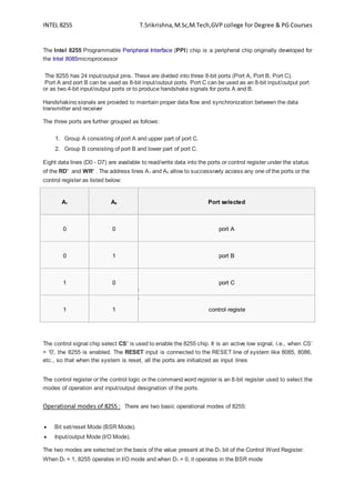
- 1. INTEL 8255 T.Srikrishna,M.Sc,M.Tech,GVP college for Degree & PG Courses The Intel 8255 Programmable Peripheral Interface (PPI) chip is a peripheral chip originally developed for the Intel 8085microprocessor The 8255 has 24 input/output pins. These are divided into three 8-bit ports (Port A, Port B, Port C). Port A and port B can be used as 8-bit input/output ports. Port C can be used as an 8-bit input/output port or as two 4-bit input/output ports or to produce handshake signals for ports A and B. Handshaking signals are provided to maintain proper data flow and synchronization between the data transmitter and receiver The three ports are further grouped as follows: 1. Group A consisting of port A and upper part of port C. 2. Group B consisting of port B and lower part of port C. Eight data lines (D0 - D7) are available to read/write data into the ports or control register under the status of the RD’ and WR’ . The address lines A1 and A0 allow to successively access any one of the ports or the control register as listed below: A1 A0 Port selected 0 0 port A 0 1 port B 1 0 port C 1 1 control registe The control signal chip select CS’ is used to enable the 8255 chip. It is an active low signal, i.e., when CS’ = '0', the 8255 is enabled. The RESET input is connected to the RESET line of system like 8085, 8086, etc., so that when the system is reset, all the ports are initialized as input lines The control register or the control logic or the command word register is an 8-bit register used to select the modes of operation and input/output designation of the ports. Operational modes of 8255 : There are two basic operational modes of 8255: Bit set/reset Mode (BSR Mode). Input/output Mode (I/O Mode). The two modes are selected on the basis of the value present at the D7 bit of the Control Word Register. When D7 = 1, 8255 operates in I/O mode and when D7 = 0, it operates in the BSR mode
- 2. INTEL 8255 T.Srikrishna,M.Sc,M.Tech,GVP college for Degree & PG Courses Bit set/reset (BSR) mode: The Bit Set/Reset (BSR) mode is applicable to port C only. Each line of port C (PC0 - PC7) can be set/reset by suitably loading the control word register. BSR mode and I/O mode are independent and selection of BSR mode does not affect the operation of other ports in I/O mode D7 bit is always 0 for BSR mode. Bits D6, D5 and D4 are don't care bits. Bits D3, D2 and D1 are used to select the pin of Port C. Bit D0 is used to set/reset the selected pin of Port C. Selection of port C pin is determined as follows: B3 B2 B1 Bit/pin of port C selected 0 0 0 PC0 0 0 1 PC1 0 1 0 PC2 0 1 1 PC3 1 0 0 PC4 1 0 1 PC5 1 1 0 PC6 1 1 1 PC7
- 3. INTEL 8255 T.Srikrishna,M.Sc,M.Tech,GVP college for Degree & PG Courses As an example, if it is needed that PC5 be set, then in the control word, 1. Since it is BSR mode, D7 = '0'. 2. Since D4, D5, D6 are not used, assume them to be '0'. 3. PC5 has to be selected, hence, D3 = '1', D2 = '0', D1 = '1'. 4. PC5 has to be set, hence, D0 = '1'. Thus, as per the above values, 0B (Hex) will be loaded into the Control Word Register (CWR). D7 D6 D5 D4 D3 D2 D1 D0 0 0 0 0 1 0 1 1 Input/output mode: This mode is selected when D7 bit of the Control Word Register is 1. There are three I/O modes: 1. Mode 0 - Simple I/O 2. Mode 1 - Strobed I/O 3. Mode 2 - Strobed Bi-directional I/O Control Word Format D0, D1, D3, D4 are assigned for lower port C, port B, upper port C and port A respectively. When these bits are 1, the corresponding port acts as an input port. If these bits are 0, then the corresponding port acts as an output port. D2 is used for mode selection of Group B (port B and lower port C). When D2 = 0, mode 0 is selected and when D2 = 1, mode 1 is selected. D5 & D6 are used for mode selection of Group A ( port A and upper port C). The selection is done as follows
- 4. INTEL 8255 T.Srikrishna,M.Sc,M.Tech,GVP college for Degree & PG Courses D6 D5 Mode 0 0 0 0 1 1 1 X 2 As it is I/O mode, D7 = 1. For example, if port B and upper port C have to be initialized as input ports and lower port C and port A as output ports (all in mode 0): 1. Since it is an I/O mode, D7 = 1. 2. Mode selection bits, D2, D5, D6 are all 0 for mode 0 operation. 3. Port B and upper port C should operate as Input ports, hence, D1 = D3 = 1. 4. Port A and lower port C should operate as Output ports, hence, D4 = D0 = 0. Hence, for the desired operation, the control word register will have to be loaded with "10001010" = 8A (hex).
- 5. INTEL 8255 T.Srikrishna,M.Sc,M.Tech,GVP college for Degree & PG Courses Mode 0 - simple I/O In this mode, the ports can be used for simple I/O operations without handshaking signals. Port A, port B provide simple I/O operation. The two halves of port C can be either used together as an additional 8-bit port, or they can be used as individual 4-bit ports. Since the two halves of port C are independent, they may be used such that one-half is initialized as an input port while the other half is initialized as an output port. Mode 0 – input mode In the input mode, the 8255 gets data from the external peripheral ports and the CPU reads the received data via its data bus. The CPU first selects the 8255 chip by making CS’ low. Then it selects the desired port using A0 and A1 lines. The CPU then issues an RD’ signal to read the data from the external peripheral device via the system data bus Mode 0 - output mode In the output mode, the CPU sends data to 8255 via system data bus and then the external peripheral ports receive this data via 8255 port. CPU first selects the 8255 chip by making CS’ low. It then selects the desired port using A0 and A1 lines. CPU then issues a WR’ signal to write data to the selected port via the system data bus. This data is then received by the external peripheral device connected to the selected port. Mode 1 When we wish to use port A or port B for handshake (strobed) input or output operation, we initialise that port in mode 1, some of the pins of port C function as handshake lines. For port B in this mode (irrespective of whether is acting as an input port or output port), PC0, PC1 and PC2 pins function as handshake lines. If port A is initialised as mode 1 input port, then, PC3, PC4 and PC5 function as handshake signals. Pins PC6 and PC7 are available for use as input/output lines. Mode 2 This mode of operation of 8255 is also called as strobed bidirectional I/O. This mode of operation provides 8255 with additional features for communicating with a peripheral device on an 8-bit data bus. Handshaking signals are provided to maintain proper data flow and synchronization between the data transmitter and receiver. The interrupt generation and other functions are similar to mode 1. • In this mode, 8255 is a bidirectional 8-bit port with handshake signals. The RD and WR signals decide whether the 8255 is going to operate as an input port or output port.
- 6. INTEL 8255 T.Srikrishna,M.Sc,M.Tech,GVP college for Degree & PG Courses
- 7. INTEL 8255 T.Srikrishna,M.Sc,M.Tech,GVP college for Degree & PG Courses