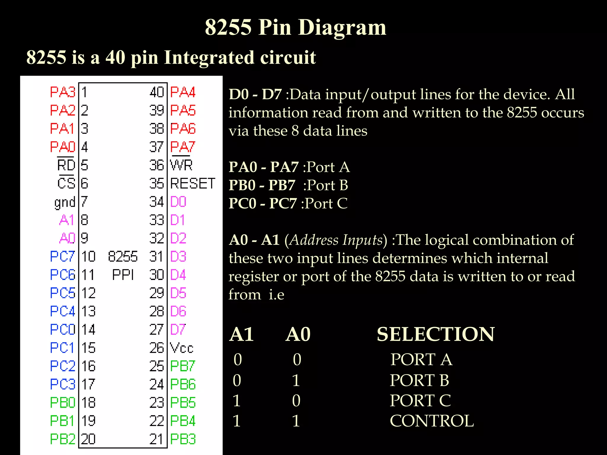
(RIA) Call Girls Bhosari ( 7001035870 ) HI-Fi Pune Escorts Service
8255 Introduction
1. The Programmable Peripheral Interface
(8255)
By:
Sharmila Chidaravalli
Asst. Prof.
Dept. of ISE,
Global Academy of Technology
2. Features
• Three 8-bit I/O ports PA, PB, PC
• PC has two 4-bit ports: PC upper (PCU) and PC lower (PCL)
• Programmed in two basic modes:
1.Bit Set/Reset (BSR) mode
2.Input/Output mode
• BSR-used to set/reset the bits in Port C
• I/O mode –divided into 3 modes
1.Simple I/O
2.I/O with handshake
3.Bi-Directional I/O
3. 8255 Pin Diagram
8255 is a 40 pin Integrated circuit
D0 - D7 :Data input/output lines for the device. All
information read from and written to the 8255 occurs
via these 8 data lines
PA0 - PA7 :Port A
PB0 - PB7 :Port B
PC0 - PC7 :Port C
A0 - A1 (Address Inputs) :The logical combination of
these two input lines determines which internal
register or port of the 8255 data is written to or read
from i.e
A1 A0 SELECTION
0 0 PORT A
0 1 PORT B
1 0 PORT C
1 1 CONTROL
4. 8255 Pin Diagram
8255 is a 40 pin Integrated circuit
CS (Chip Select Input): If this line is a logical 0, the
microprocessor can read and write to the 8255
RD (Read Input) :If CS is logical 0 and the RD
input is a logical 0,
Microprocessor 8255Reads data
WR (Write Input) :If CS is a logical 0 and the WR
input is a logical 0, data is written to the 8255
Microprocessor 8255Writes data
RESET: The 8255 is placed into its reset state if
this input line is a logical 1. All peripheral ports
are set to the input mode
6. 8255 Operational Modes
Mode 0:Simple Input/Output
No handshake, port A, B, C(upper part) and C(lower part) can
work independently for input/ output.
All ports can be used for I/O
7. 8255 Operational Modes
Mode 1:Input/Output With Handshake
Single handshake, port A, B can be used independently for input/
output, port C is only used for handshaking
Port A and port B uses difference sets of pins for Input and Output
8. 8255 Operational Modes
Mode 2:Bi-directional Input/Output With Handshake
For port A only. Implements bi-directional handshake.
Port A uses pins PC3 – PC7 for mode 2; PC0 PC3 depends on‐
which mode port B is in.
9. Note:
Port A can work in Mode 0,Mode 1 or Mode 2
Port B can work in Mode 0 or Mode 1
Port C can work in Mode 0 only
OR
Port A, Port B and Port C can work in Mode 0
Port A and Port B can work in Mode 1
Only Port A can work in Mode 2
10. Control Words
2 control words in 8255:
1.Port C Bit Set /Reset control word
2.Mode Definition control word
1.Port C Bit Set /Reset control word
Used for setting to 1 or resetting to 0 any one selected bit of port C
11. 8255 Mode Definition Control Word
Mode Definition control word is used to configure the ports of 8255 as
input or output in mode 0,mode 1,mode 2