

Recommended
More Related Content
What's hot
What's hot (20)
Similar to interrupts of 8051.pdf
Similar to interrupts of 8051.pdf (20)
More from Srikrishna Thota
More from Srikrishna Thota (19)
Recently uploaded
Recently uploaded (20)
interrupts of 8051.pdf
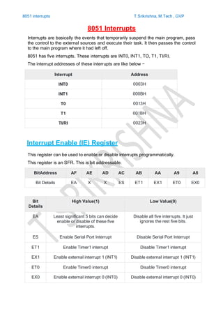
- 1. 8051 interrupts T.Srikrishna, M.Tech , GVP 8051 Interrupts Interrupts are basically the events that temporarily suspend the main program, pass the control to the external sources and execute their task. It then passes the control to the main program where it had left off. 8051 has five interrupts. These interrupts are INT0, INT1, TO, T1, TI/RI. The interrupt addresses of these interrupts are like below − Interrupt Address INT0 0003H INT1 000BH T0 0013H T1 001BH TI/RI 0023H Interrupt Enable (IE) Register This register can be used to enable or disable interrupts programmatically. This register is an SFR. This is bit addressable. BitAddress AF AE AD AC AB AA A9 A8 Bit Details EA X X ES ET1 EX1 ET0 EX0 Bit Details High Value(1) Low Value(0) EA Least significant 5 bits can decide enable or disable of these five interrupts. Disable all five interrupts. It just ignores the rest five bits. ES Enable Serial Port Interrupt Disable Serial Port Interrupt ET1 Enable Timer1 interrupt Disable Timer1 interrupt EX1 Enable external interrupt 1 (INT1) Disable external interrupt 1 (INT1) ET0 Enable Timer0 interrupt Disable Timer0 interrupt EX0 Enable external interrupt 0 (INT0) Disable external interrupt 0 (INT0)
- 2. 8051 interrupts T.Srikrishna, M.Tech , GVP Interrupt Priority (IP) Register The priority levels are level 1 and level 0. Priority level 1 indicates the higher priority, and level 0 indicates lower priority. This IP register can be used to store the priority levels for each interrupt. This is also a bit addressable SFR. BitAddress BF BE BD BC BB BA B9 B8 Bit Details X X X PS PT1 PX1 PT0 PX0 Bit Details High Value(1) Low Value(0) PS Set 1 level priority of Serial port interrupt Set 0 level priority of Serial port interrupt PT1 Set 1 level priority of Timer1 interrupt Set 0 level priority of Timer1 interrupt PX1 Set 1 level priority of external interrupt 1 (INT1) Set 0 level priority of external interrupt 1 (INT1) PT0 Set 1 level priority of Timer0 interrupt Set 0 level priority of Timer0 interrupt PX0 Set 1 level priority of external interrupt 0 (INT0) Set 0 level priority of external interrupt 0 (INT0) When all of the five interrupts are in same priority level, and if all of the interrupts are enabled, then the sequence of interrupts will be INT0, T0, INT1, T1, TI/R I. Some specific priority register value can be used to maintain the priorities of the interrupts. Example: Let the value of Priority register is xxx00101 indicates the sequence INT0, INT1, TI/RI, T1, T0. External Interrupt The external interrupts of 8051 are INT0and. INT1 .These interrupts can be programmed to either edge-triggered or level triggered. The TCON register can be used to program external interrupts to edge or level triggered. TCON register The TCON is Timer Control. TCON is another bit addressable SFR. BitAddress 8F 8E 8D 8C 8B 8A 89 88 Bit Details TF1 TR1 TF0 TR0 IE1 IT1 IE0 IT0
- 3. 8051 interrupts T.Srikrishna, M.Tech , GVP Bit Details High Value(1) Low Value(0) IT0 Set ( INT0) as negative edge triggered input. Set ( INT0) as active low level triggered input. IT1 Set ( INT1) as negative edge triggered input. Set ( INT1) as active low level triggered input. IE0 This will be 1, when INT0is activated as level triggered. This will be 0, when INT0is activated as edge triggered. IE1 This will be 1, when INT1 is activated as level triggered. This will be 0, when INT1 is activated as edge triggered. TR0 Set Timer0 as run mode Set Timer0 as stop mode. TR1 Set Timer1 as run mode Set Timer1 as stop mode. TF0 High when Timer T0 overflow occurs. After resetting the timer T0 thiswill also be changed to 0 state TF1 High when Timer T1 overflow occurs. After resetting the timer T1 this will also be changed to 0 state. The IT0 and IT1 are stands for Interrupt Type. These bits are used to decide whether the INT0 and INT1 will be level trigged or edge triggered. IE0 and IE1 bits are used to indicate the status of external interrupts. These bit can be set or reset by the microcontroller itself. The first four bits are the status information about timers. When TR0 and TR1 are 1, it indicates the running mode of the timers. The TF0 and TF1 are used to indicate the overflow of timer T0 and T1 respectively. When over flow occurs these flags are set to 1. Serial Port Interrupt The serial ports can be used either Transmitting mode or reception mode. The interrupt status for the Transmission is provided by TI, and status for Reception is provided by RI. SCON Register These are two bits of SCON(Serial Control). This is also a bit addressable SFR. BitAddress 9F 9E 9D 9C 9B 9A 99 98 Bit Details SM0 SM1 SM2 REN TB8 RB8 TI RI