Downloaded 176 times

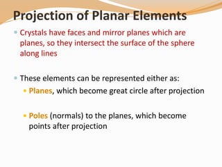
![The following rules are applied:
All crystal faces are plotted as poles (lines perpendicular to the
crystal face. Thus, angles between crystal faces are really
angles between poles to crystal faces
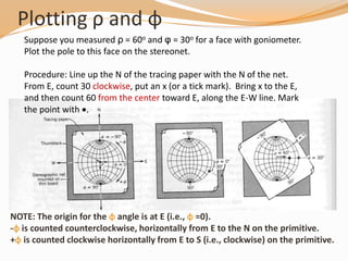
The b crystallographic axis is taken as the starting point. Such
an axis will be perpendicular to the (010) crystal face in any
crystal system. The [010] axis (note the zone symbol) or (010)
crystal face will therefore plot at φ = 0o and ρ = 90o
Positive φ angles will be measured clockwise on the stereonet,
and negative φ angles will be measured counter-clockwise on
the stereonet](https://image.slidesharecdn.com/stereographicprojection-181209070039/85/Stereographic-projection-crystallography-29-320.jpg)


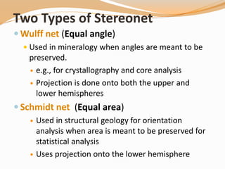
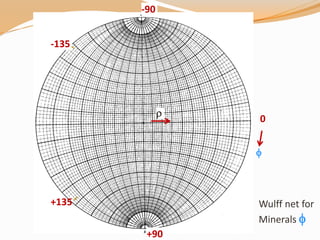
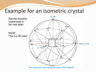
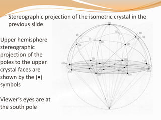
This document provides an overview of stereographic projection as it relates to crystals. It discusses how stereographic projection preserves the 3D angular relationships of crystals in a 2D representation. It covers the key aspects of stereographic projection including the two main types of stereonets (Wulff and Schmidt), how to project lines, planes, and symmetry elements, and the conventions and steps to plot crystallographic data. Examples are provided to demonstrate how to plot poles to faces and measure angles on a stereonet for both isometric and general crystals.


