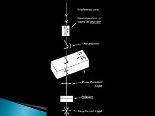
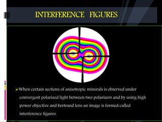
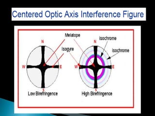
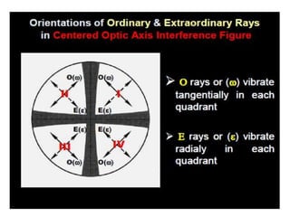
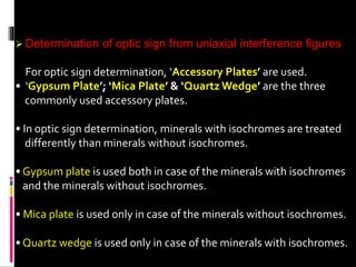
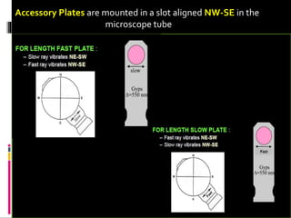
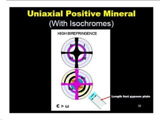
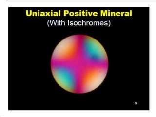
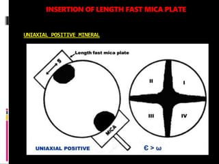
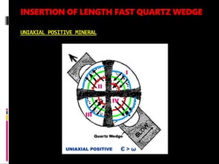
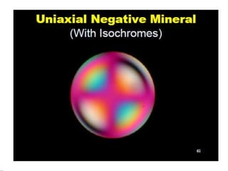
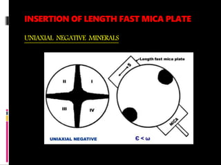
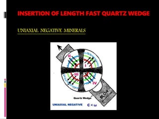
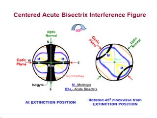
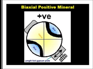
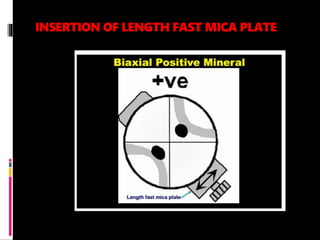
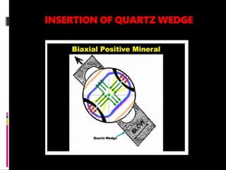
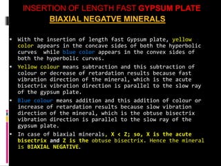
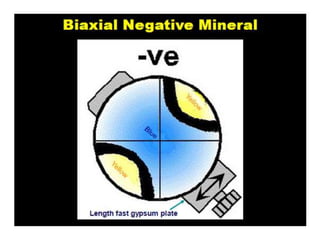
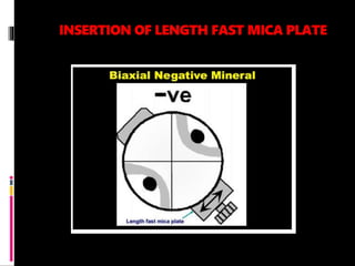
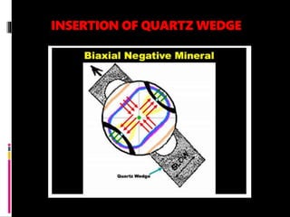
DR. HARISINGH GOUR VISHWAVIDYALAYA
SAGAR,M.P
(A CENTRAL UNIVERSITY)
DEPARTMENT OF APPLIED GEOLOGY
Topic- Interference colours and Interference figures
Under Guidance Of- Presented by-
Prof. R.K. Trivedi Dipankar Sonowal
Reg No.Y18251011
Contents
1. Interference colour
2. Interference figures : Centered optic axis interference figure
3. Uniaxial interference figures
4. Determination of optic sign from uniaxial interference figures
5. Uniaxial positive mineral : Insertion of length fast gypsum plate, mica
plate and quartz wedge
6. Uniaxial negative mineral: Insertion of length fast gypsum plate, mica
plate and quartz wedge
7. Biaxial interference figures:Centered acute bisectrix interference
figure
8. Biaxial positive mineral: Insertion of length fast gypsum plate, mica
plate and quartz wedge
9. Biaxial negative mineral: Insertion of length fast gypsum plate, mica
plate and quartz wedge
10. Reference
 When an anisotropic mineral in thin section is
viewed under cross polars of a petrological
microscope, it shows some colours apart from four
positions of darkness (extinction positions) with a
complete rotation of the microscope stage.
 This colour is called ‘INTERFERENCE COLOUR’’.
 The maximum interference between two rays takes place
when the mineral thin section is placed 45° from its
extinction position. Therefore, maximum interference colour
for a particular mineral is observed when it is viewed 45°
from its extinction position. This is the standard procedure
to determine interference colour of a mineral in thin section.
INTERFERENCE FIGURES
When certain sections of anisotropic minerals is observed under
convergent polarized light between two polarizers and by using high
power objective and bertrand lens an image is formed called
interference figures.
 Under orthoscopic view of the petrological microscope, we can at
best know whether the mineral in thin section is ‘Isotropic’ or
‘Anisotropic’. But in case of anisotropic minerals, whether it is
‘Uniaxial’ or ‘Biaxial’ we can not ascertain under orthoscopic view
of the microscope.
 However, under conoscopic view of the microscope, both uniaxial
and biaxial minerals show different as well as distinctive types of
interference figures, from which we can very easily ascertain
whether the mineral is ‘Uniaxial’ or ‘Biaxial’.
 Moreover, with the help of ‘Accessory Plates’, it can be found out
whether the uniaxial or the biaxial mineral is ‘+ve’ or ‘-ve’ from
their respective interference figures, and this determination is
known as the ‘DETERMINATION OF OPTIC SIGN OF MINERALS’
UNIAXIAL
INTERFERENCE FIGURES
 Centered Optic axis interference figure :
A mineral section cut normal to the optic axis of uniaxial
mineral produce the simplest and most important
interference figure. The interference figure consists of
isogyres forming a dark cross superimposed on circular
rings called isochromes. The point in the centre where the
isogyres cross is called as melatope, which represents the optic
axis itself.
Isochromes are visible only in case of minerals having
moderate to high birefringence. In case of minerals with low
birefringence, isochromes are not at all visible.
 Determination of optic sign from uniaxial interference figures
For optic sign determination, ‘Accessory Plates’ are used.
• ‘Gypsum Plate’; ‘Mica Plate’ & ‘Quartz Wedge’ are the three
commonly used accessory plates.
• In optic sign determination, minerals with isochromes are treated
differently than minerals without isochromes.
• Gypsum plate is used both in case of the minerals with isochromes
and the minerals without isochromes.
• Mica plate is used only in case of the minerals without isochromes.
• Quartz wedge is used only in case of the minerals with isochromes.
Accessory Plates are mounted in a slot aligned NW-SE in the
microscope tube
 With fast ray of the mineral parallel to fast ray of the
accessory plate – retardation increases (ADDITION)
 With fast ray of the mineral parallel to slow ray of the
accessory plate – retardation decreases (SUBTRACTION)
 With slow ray of the mineral parallel to fast ray of the
accessory plate – retardation decreases (SUBTRACTION)
 With slow ray of the mineral parallel to slow ray of the
accessory plate – retardation increases (ADDITION)
Insertion of Length Fast GYPSUM PLATE
UNIAXIAL POSITIVE MINERAL
With the insertion of length fast Gypsum plate, yellow color
appears in quadrants II & IV, which indicates subtraction.
Yellow colour means subtraction and this subtraction of colour
or decrease of retardation results because slow ray of the
mineral i.e. E rays or (e) is parallel to fast ray of the gypsum
plate.
Similarly, blue color appears in quadrants I & III indicating
addition.
Blue colour means addition and this addition of colour or
increase of retardation results because slow ray of the mineral
i.e. E ray or (e) is parallel to slow ray of the gypsum plate.
Therefore, E ray is slower than O ray
INSERTION OF LENGTH FAST MICA PLATE
UNIAXIAL POSITIVE MINERAL
INSERTION OF LENGTH FAST QUARTZ WEDGE
UNIAXIAL POSITIVE MINERAL
INSERTION OF LENGTH FAST GYPSUM PLATE
UNIAXIAL NEGATIVE MINERALS
• With the insertion of length fast gypsum plate, blue color
appears in quadrants ii & iv, which indicates addition.
• Blue colour means addition and this addition of colour or
increase of retardation results because fast ray of the mineral
i.e. E rays or (e) is parallel to fast ray of the gypsum plate.
• Similarly, yellow color appears in quadrants i & iii indicating
subtraction.
•Yellow colour means subtraction and this subtraction of
colour or decrease of retardation results because fast ray of
the mineral i.e. E ray or (e) is parallel to slow ray of the
gypsum plate.
•Therefore, e ray is faster than o ray or e < w i.E. Uniaxial
negative.
INSERTION OF LENGTH FAST MICA PLATE
UNIAXIAL NEGATIVE MINERALS
INSERTION OF LENGTH FAST QUARTZ WEDGE
UNIAXIAL NEGATIVE MINERALS
CENTERED ACUTE BISECTRIX INTERFERENCE FIGURE
THE CENTERED ACUTE INTERFERENCE FIGURE CONSISTS OF:
A black cross consisting of two ‘ISOGYRES’ of unequal thickness;N-S isogyre is
thick & E-W isogyre is thin.The intersecting point of the two isogyres coincides
with the centre of the microscope cross hairs.
On the E-W isogyre, there are two ‘MELATOPES’, which represent the two optic
axes themselves.
The two melatopes are encircled by concentric coloured rings called
‘ISOCHROMES’. Isochromes are visible only in case of minerals having moderate to
high birefringence. In case of minerals with low birefringence, isochromes are not
at all visible.
The interference figure changes its overall configuration with a slight rotation of
the microscope stage from the extinction position and the isogyres split into two
hyperbolic curves of equal sizes with clockwise or anti-clockwise 450 rotation of the
microscope stage.
INSERTION OF LENGTH FAST GYPSUM PLATE
BIAXIAL POSITIVE MINERALS
With the insertion of length fast Gypsum plate, blue color
appears in the concave sides of both the hyperbolic curves while
yellow color appears in the convex sides of both the hyperbolic
curves.
Blue colour means addition and this addition of colour or
increase of retardation results because slow vibration direction
of the mineral, which is the acute bisectrix vibration direction
is parallel to the slow ray of the gypsum plate.
Yellow colour means subtraction and this subtraction of colour or
decrease of retardation results because fast vibration direction
of the mineral, which is the obtuse bisectrix vibration direction
is parallel to the slow ray of the gypsum plate.
In case of biaxial minerals, X > Z; so, Z is the acute bisectrix
and X is the obtuse bisectrix.Hence the mineral is BIAXIAL
POSITIVE.
INSERTION OF LENGTH FAST MICA PLATE
INSERTION OF QUARTZ WEDGE
INSERTION OF LENGTH FAST GYPSUM PLATE
BIAXIAL NEGATVE MINERALS
 With the insertion of length fast Gypsum plate, yellow
color appears in the concave sides of both the hyperbolic
curves while blue color appears in the convex sides of
both the hyperbolic curves.
 Yellow colour means subtraction and this subtraction of
colour or decrease of retardation results because fast
vibration direction of the mineral, which is the acute
bisectrix vibration direction is parallel to the slow ray
of the gypsum plate.
 Blue colour means addition and this addition of colour or
increase of retardation results because slow vibration
direction of the mineral, which is the obtuse bisectrix
vibration direction is parallel to the slow ray of the
gypsum plate.
 In case of biaxial minerals, X < Z; so, X is the acute
bisectrix and Z is the obtuse bisectrix. Hence the mineral
is BIAXIAL NEGATIVE.
INSERTION OF LENGTH FAST MICA PLATE
INSERTION OF QUARTZ WEDGE
• Introduction to mineralogy byWilliam D.Nesse
• P.O.Alexander, A handbook of minerals, crystals ,rocks and ores
• Wikipedia
• Image Courtesy- www.google.com
Reference
Interference colour and interference  figures

Interference colour and interference figures

  • 1.
    DR. HARISINGH GOURVISHWAVIDYALAYA SAGAR,M.P (A CENTRAL UNIVERSITY) DEPARTMENT OF APPLIED GEOLOGY Topic- Interference colours and Interference figures Under Guidance Of- Presented by- Prof. R.K. Trivedi Dipankar Sonowal Reg No.Y18251011
  • 2.
    Contents 1. Interference colour 2.Interference figures : Centered optic axis interference figure 3. Uniaxial interference figures 4. Determination of optic sign from uniaxial interference figures 5. Uniaxial positive mineral : Insertion of length fast gypsum plate, mica plate and quartz wedge 6. Uniaxial negative mineral: Insertion of length fast gypsum plate, mica plate and quartz wedge 7. Biaxial interference figures:Centered acute bisectrix interference figure 8. Biaxial positive mineral: Insertion of length fast gypsum plate, mica plate and quartz wedge 9. Biaxial negative mineral: Insertion of length fast gypsum plate, mica plate and quartz wedge 10. Reference
  • 3.
     When ananisotropic mineral in thin section is viewed under cross polars of a petrological microscope, it shows some colours apart from four positions of darkness (extinction positions) with a complete rotation of the microscope stage.  This colour is called ‘INTERFERENCE COLOUR’’.
  • 6.
     The maximuminterference between two rays takes place when the mineral thin section is placed 45° from its extinction position. Therefore, maximum interference colour for a particular mineral is observed when it is viewed 45° from its extinction position. This is the standard procedure to determine interference colour of a mineral in thin section.
  • 7.
    INTERFERENCE FIGURES When certainsections of anisotropic minerals is observed under convergent polarized light between two polarizers and by using high power objective and bertrand lens an image is formed called interference figures.
  • 8.
     Under orthoscopicview of the petrological microscope, we can at best know whether the mineral in thin section is ‘Isotropic’ or ‘Anisotropic’. But in case of anisotropic minerals, whether it is ‘Uniaxial’ or ‘Biaxial’ we can not ascertain under orthoscopic view of the microscope.  However, under conoscopic view of the microscope, both uniaxial and biaxial minerals show different as well as distinctive types of interference figures, from which we can very easily ascertain whether the mineral is ‘Uniaxial’ or ‘Biaxial’.  Moreover, with the help of ‘Accessory Plates’, it can be found out whether the uniaxial or the biaxial mineral is ‘+ve’ or ‘-ve’ from their respective interference figures, and this determination is known as the ‘DETERMINATION OF OPTIC SIGN OF MINERALS’
  • 9.
    UNIAXIAL INTERFERENCE FIGURES  CenteredOptic axis interference figure : A mineral section cut normal to the optic axis of uniaxial mineral produce the simplest and most important interference figure. The interference figure consists of isogyres forming a dark cross superimposed on circular rings called isochromes. The point in the centre where the isogyres cross is called as melatope, which represents the optic axis itself. Isochromes are visible only in case of minerals having moderate to high birefringence. In case of minerals with low birefringence, isochromes are not at all visible.
  • 12.
     Determination ofoptic sign from uniaxial interference figures For optic sign determination, ‘Accessory Plates’ are used. • ‘Gypsum Plate’; ‘Mica Plate’ & ‘Quartz Wedge’ are the three commonly used accessory plates. • In optic sign determination, minerals with isochromes are treated differently than minerals without isochromes. • Gypsum plate is used both in case of the minerals with isochromes and the minerals without isochromes. • Mica plate is used only in case of the minerals without isochromes. • Quartz wedge is used only in case of the minerals with isochromes.
  • 13.
    Accessory Plates aremounted in a slot aligned NW-SE in the microscope tube
  • 14.
     With fastray of the mineral parallel to fast ray of the accessory plate – retardation increases (ADDITION)  With fast ray of the mineral parallel to slow ray of the accessory plate – retardation decreases (SUBTRACTION)  With slow ray of the mineral parallel to fast ray of the accessory plate – retardation decreases (SUBTRACTION)  With slow ray of the mineral parallel to slow ray of the accessory plate – retardation increases (ADDITION)
  • 15.
    Insertion of LengthFast GYPSUM PLATE UNIAXIAL POSITIVE MINERAL With the insertion of length fast Gypsum plate, yellow color appears in quadrants II & IV, which indicates subtraction. Yellow colour means subtraction and this subtraction of colour or decrease of retardation results because slow ray of the mineral i.e. E rays or (e) is parallel to fast ray of the gypsum plate. Similarly, blue color appears in quadrants I & III indicating addition. Blue colour means addition and this addition of colour or increase of retardation results because slow ray of the mineral i.e. E ray or (e) is parallel to slow ray of the gypsum plate. Therefore, E ray is slower than O ray
  • 20.
    INSERTION OF LENGTHFAST MICA PLATE UNIAXIAL POSITIVE MINERAL
  • 21.
    INSERTION OF LENGTHFAST QUARTZ WEDGE UNIAXIAL POSITIVE MINERAL
  • 22.
    INSERTION OF LENGTHFAST GYPSUM PLATE UNIAXIAL NEGATIVE MINERALS • With the insertion of length fast gypsum plate, blue color appears in quadrants ii & iv, which indicates addition. • Blue colour means addition and this addition of colour or increase of retardation results because fast ray of the mineral i.e. E rays or (e) is parallel to fast ray of the gypsum plate. • Similarly, yellow color appears in quadrants i & iii indicating subtraction. •Yellow colour means subtraction and this subtraction of colour or decrease of retardation results because fast ray of the mineral i.e. E ray or (e) is parallel to slow ray of the gypsum plate. •Therefore, e ray is faster than o ray or e < w i.E. Uniaxial negative.
  • 27.
    INSERTION OF LENGTHFAST MICA PLATE UNIAXIAL NEGATIVE MINERALS
  • 28.
    INSERTION OF LENGTHFAST QUARTZ WEDGE UNIAXIAL NEGATIVE MINERALS
  • 30.
    CENTERED ACUTE BISECTRIXINTERFERENCE FIGURE THE CENTERED ACUTE INTERFERENCE FIGURE CONSISTS OF: A black cross consisting of two ‘ISOGYRES’ of unequal thickness;N-S isogyre is thick & E-W isogyre is thin.The intersecting point of the two isogyres coincides with the centre of the microscope cross hairs. On the E-W isogyre, there are two ‘MELATOPES’, which represent the two optic axes themselves. The two melatopes are encircled by concentric coloured rings called ‘ISOCHROMES’. Isochromes are visible only in case of minerals having moderate to high birefringence. In case of minerals with low birefringence, isochromes are not at all visible. The interference figure changes its overall configuration with a slight rotation of the microscope stage from the extinction position and the isogyres split into two hyperbolic curves of equal sizes with clockwise or anti-clockwise 450 rotation of the microscope stage.
  • 32.
    INSERTION OF LENGTHFAST GYPSUM PLATE BIAXIAL POSITIVE MINERALS With the insertion of length fast Gypsum plate, blue color appears in the concave sides of both the hyperbolic curves while yellow color appears in the convex sides of both the hyperbolic curves. Blue colour means addition and this addition of colour or increase of retardation results because slow vibration direction of the mineral, which is the acute bisectrix vibration direction is parallel to the slow ray of the gypsum plate. Yellow colour means subtraction and this subtraction of colour or decrease of retardation results because fast vibration direction of the mineral, which is the obtuse bisectrix vibration direction is parallel to the slow ray of the gypsum plate. In case of biaxial minerals, X > Z; so, Z is the acute bisectrix and X is the obtuse bisectrix.Hence the mineral is BIAXIAL POSITIVE.
  • 34.
    INSERTION OF LENGTHFAST MICA PLATE
  • 35.
  • 36.
    INSERTION OF LENGTHFAST GYPSUM PLATE BIAXIAL NEGATVE MINERALS  With the insertion of length fast Gypsum plate, yellow color appears in the concave sides of both the hyperbolic curves while blue color appears in the convex sides of both the hyperbolic curves.  Yellow colour means subtraction and this subtraction of colour or decrease of retardation results because fast vibration direction of the mineral, which is the acute bisectrix vibration direction is parallel to the slow ray of the gypsum plate.  Blue colour means addition and this addition of colour or increase of retardation results because slow vibration direction of the mineral, which is the obtuse bisectrix vibration direction is parallel to the slow ray of the gypsum plate.  In case of biaxial minerals, X < Z; so, X is the acute bisectrix and Z is the obtuse bisectrix. Hence the mineral is BIAXIAL NEGATIVE.
  • 38.
    INSERTION OF LENGTHFAST MICA PLATE
  • 39.
  • 40.
    • Introduction tomineralogy byWilliam D.Nesse • P.O.Alexander, A handbook of minerals, crystals ,rocks and ores • Wikipedia • Image Courtesy- www.google.com Reference