Downloaded 320 times


![Loose Ends of Texture Setup Texture object specification Fixed-function texture binding and enabling static const GLubyte myDemonTextureImage[3*(128*128)] = { /* RGB8 image data for a mipmapped 128x128 demon texture */ #include "demon_image.h" }; /* Tightly packed texture data. */ glPixelStorei ( GL_UNPACK_ALIGNMENT , 1); glBindTexture ( GL_TEXTURE_2D , 666 ); /* Load demon decal texture with mipmaps. */ gluBuild2DMipmaps ( GL_TEXTURE_2D , GL_RGB8 , 128, 128, GL_RGB , GL_UNSIGNED_BYTE , myDemonTextureImage); glTexParameteri ( GL_TEXTURE_2D , GL_TEXTURE_MIN_FILTER , GL_LINEAR_MIPMAP_LINEAR ); glActiveTexture ( GL_TEXTURE0 ); glTexEnvi ( GL_TEXTURE_ENV , GL_TEXTURE_ENV_MODE , GL_REPLACE ); glEnable ( GL_TEXTURE_2D ); glBindTexture ( GL_TEXTURE_2D , 666 ); gluBuild2DMipmaps calls glTexImage2D on image, then down-samples iteratively 64x64, 32x32, 16x16, 8x8, 4x4, 2x1, and 1x1 images (called mipmap chain)](https://image.slidesharecdn.com/11texture-120223221135-phpapp02/85/CS-354-Texture-Mapping-17-320.jpg)


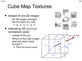
![Where do texture coordinates come from? Assigned ad-hoc by artist Tedious! Has gift wrapping problem Computed based on XYZ position Texture coordinate generation (“texgen”) Hard to map to “surface space” Function maps ( x,y,z ) to ( s,t,r,q ) From bi-varite parameterization of geometry Good when geometry is generated from patches So ( u,v ) of patch maps to ( x,y,z ) and ( s,t ) [PTex]](https://image.slidesharecdn.com/11texture-120223221135-phpapp02/85/CS-354-Texture-Mapping-21-320.jpg)


![Wrap Modes Texture image is defined in [0..1]x[0..1] region What happens outside that region? Texture wrap modes say texture s t GL_CLAMP wrapping GL_REPEAT wrapping](https://image.slidesharecdn.com/11texture-120223221135-phpapp02/85/CS-354-Texture-Mapping-25-320.jpg)
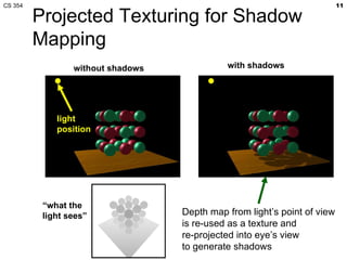
![Projective Texturing Homogenous coordinates support projection Similar to (x/w,y/w,z/w) But (s/q,t/q,r/q) instead Also used in shadow mapping Source: Wolfgang [99]](https://image.slidesharecdn.com/11texture-120223221135-phpapp02/85/CS-354-Texture-Mapping-26-320.jpg)


![What really happens? Let’s consider a simple tri-linear mip-mapped 2D projective texture fetch Logically one shader instruction float4 color = tex2Dproj(decalSampler, st); TXP o[COLR], f[TEX3], TEX2, 2D; Logically Texel selection Texel combination How many operations are involved? Assembly instruction (NV_fragment_program) High-level language statement (Cg/HLSL)](https://image.slidesharecdn.com/11texture-120223221135-phpapp02/85/CS-354-Texture-Mapping-41-320.jpg)
![Interpolation First we need to interpolate (s,t,r,q) This is the f[TEX3] part of the TXP instruction Projective texturing means we want (s/q, t/q) And possible r/q if shadow mapping In order to correct for perspective, hardware actually interpolates (s/w, t/w, r/w, q/w) If not projective texturing, could linearly interpolate inverse w (or 1/w) Then compute its reciprocal to get w Since 1/(1/w) equals w Then multiply (s/w,t/w,r/w,q/w) times w To get (s,t,r,q) If projective texturing, we can instead Compute reciprocal of q/w to get w/q Then multiple (s/w,t/w,r/w) by w/q to get (s/q, t/q, r/q) Observe projective texturing is same cost as perspective correction](https://image.slidesharecdn.com/11texture-120223221135-phpapp02/85/CS-354-Texture-Mapping-43-320.jpg)


![Intel’s Larrabee Design Recognized the Texture Fetch’s Complexity Original intended to be a multi-core x86-based graphics architecture Texture filtering still most commonly uses 8-bit color components, which can be filtered more efficiently in dedicated logic than in the 32-bit wide VPU lanes. Efficiently selecting unaligned 2x2 quads to filter requires a specialized kind of pipelined gather logic. Loading texture data into the VPU for filtering requires an impractical amount of register file bandwidth. On-the-fly texture decompression is dramatically more efficient in dedicated hardware than in CPU code.” — Larrabee: A Many-Core x86 Architecture for Visual Computing [2008] “ Larrabee includes texture filter logic because this operation cannot be efficiently performed in software on the cores. Our analysis shows that software texture filtering on our cores would take 12x to 40x longer than our fixed function logic, depending on whether decompression is required. There are four basic reasons:](https://image.slidesharecdn.com/11texture-120223221135-phpapp02/85/CS-354-Texture-Mapping-56-320.jpg)
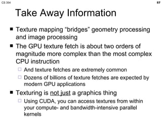


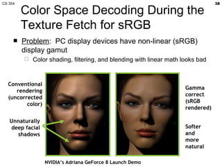
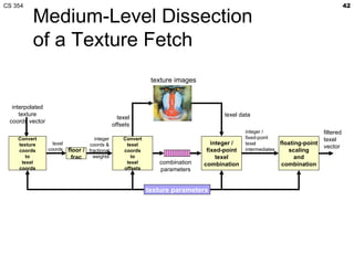
The document summarizes a lecture on texture mapping in computer graphics. It discusses topics like texture mapping fundamentals, texture coordinates, texture filtering including mipmapping and anisotropic filtering, wrap modes, cube maps, and texture formats. It also provides examples of texture mapping in games and an overview of the texture sampling process in the graphics pipeline.