Downloaded 402 times
![Atkinson Cycle, Ericsson Cycle
and Stirling Cycle
-by Group 11
[Dhaval Shukla,
Abhishek Singh R.,
Abhishek Singh
Aman Singh]
-Engineering Thermodynamics
-A.C.E.T.](https://image.slidesharecdn.com/atkinsoncycleericssoncycleandstirlingcycle-160813042807/85/Atkinson-Cycle-Ericsson-Cycle-And-Stirling-Cycle-1-320.jpg)
![Atkinson Cycle, Ericsson Cycle
and Stirling Cycle
-by Group 11
[Dhaval Shukla,
Abhishek Singh R.,
Abhishek Singh
Aman Singh]
-Engineering Thermodynamics
-A.C.E.T.](https://image.slidesharecdn.com/atkinsoncycleericssoncycleandstirlingcycle-160813042807/75/Atkinson-Cycle-Ericsson-Cycle-And-Stirling-Cycle-1-2048.jpg)
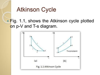
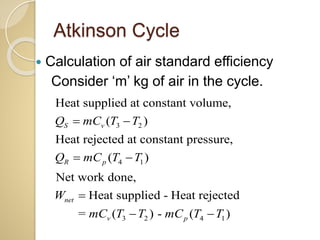
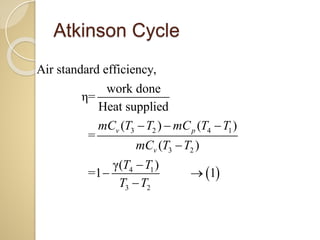
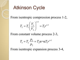
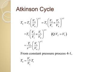
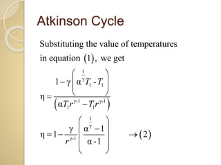
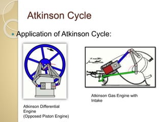
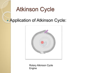
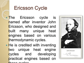
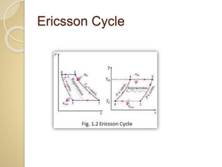
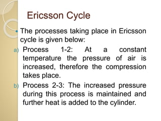
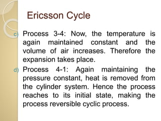
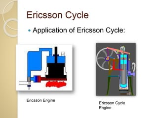
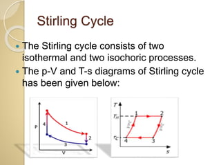
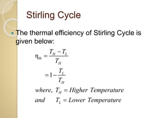
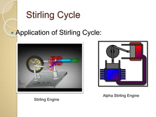
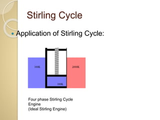


This document discusses three thermodynamic cycles - the Atkinson cycle, Ericsson cycle, and Stirling cycle. The Atkinson cycle consists of two adiabatic and two constant pressure/volume processes. The Ericsson cycle consists of two isothermal and two constant pressure processes. The Stirling cycle consists of two isothermal and two isochoric (constant volume) processes. Applications of each cycle such as engines are also mentioned.


