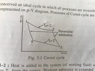
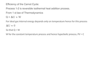
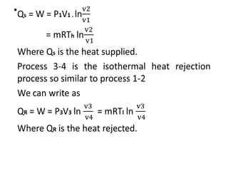
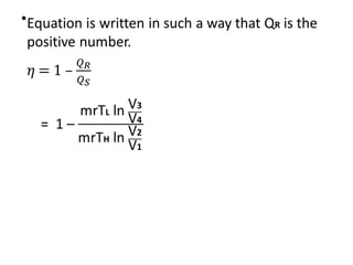
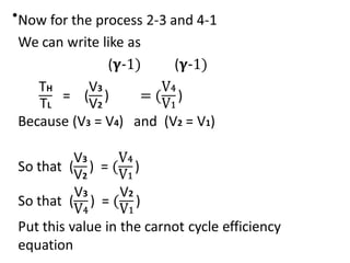
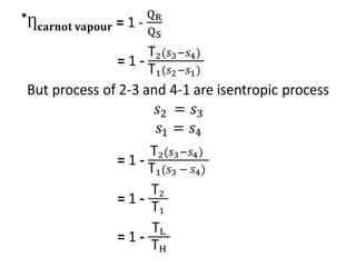
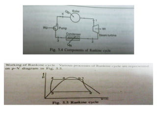
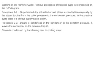
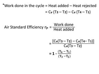
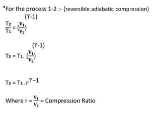
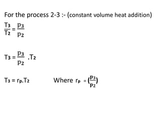
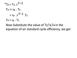
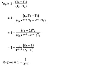
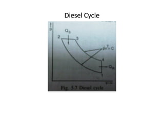
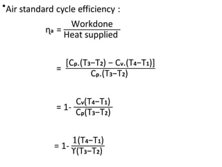
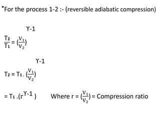
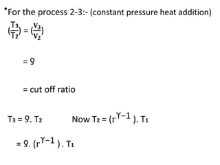
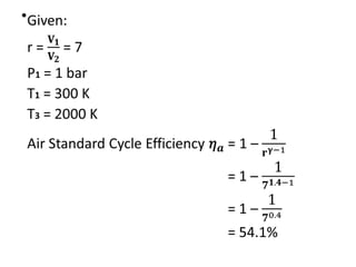
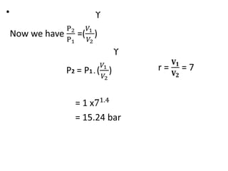
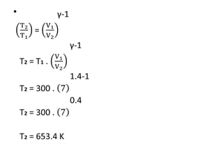
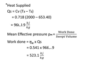
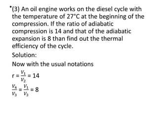
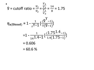
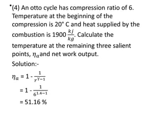
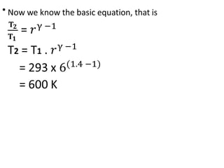
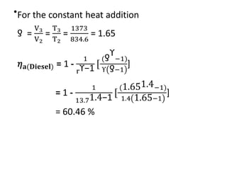
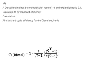
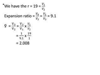
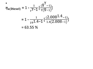
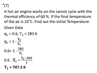
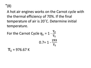
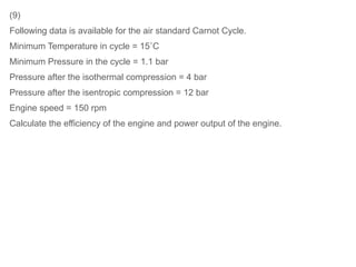
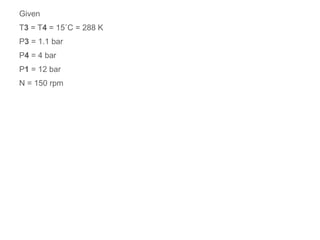
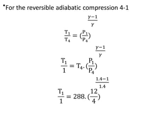
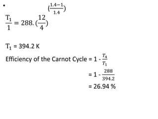
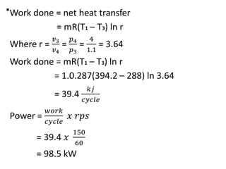
Chapter- 4 Heat Engines
Elementary heat engines :-
Heat engine is a device in which net heat is added to the engine and net work
transfer from the engine.
Thus for the heat engine net heat transfer and the net work transfer both are
positive in a cycle executed by the engine.
Heat engines can be classified in two categories
1. External combustion engines
2. Internal combustion engines
External Combustion Engine:- The combustion of the fuel take place outside
the engine.
Heat liberated by the combustion of the fuel is transferred to the working fluid of
the engine.
Such as Steam engines, steam turbines, close cycle gas turbines.
The combustion of the fuel take place in the boiler which produces high
pressure steam, this steam is expanded which produce the mechanical work.
Internal Combustion Engine:- The combustion of the fuel take place inside the engine.
Combustion of the fuel takes place with the help of air.
Combustion product it self are the working fluid of the engines.
Such as Petrol engine, Diesel engine, Open cycle gas turbines.
Difference between Internal combustion engine & External combustion engine
Internal combustion engine:-
1. They are compact in size and hence suitable for the small capacity.
2. More refined fuel is required which is costly. Generally used with liquid and
gaseous fuel.
3. Due to less components, complexity is less.
4. Lower efficiency.
5. More pollutant.
External combustion engine:-
1. They are bulky and hence designed for the large capacity.
2. Cheaper fuels can be used. Generally solid, liquid, and gaseous fuels are
used.
3. More complex.
4. Higher efficiency.
5. Less pollutant.
Essential components of Heat engine:-
A thermodynamic cycle is executed by the heat engine to produce net positive
work from net positive heat addition to the engine.
This cycle is known as the heat engine cycle. Sometimes it is also referred to
as a power cycle. A heat engine cycle consists of the series of the processes
which operate with particular devices.
The essential components of heat engine are as follows:-
1.
Heat source:- It is a reservoir of the heat from which heat is supplied to the working
fluid.
Example as a furnace of boiler, combustion chamber of I.C engine.
2.
Heat sink:- A heat sink is a low temperature reservoir where heat is rejected by the
working fluid.
3.
Working fluid:- Substance which receive and reject heat and undergoes various
processes of heat engine cycle is called working fluid.
4. Expander:- It is the device in which working
fluid is expanded and work is available.
5. Compressor:- It is a device in which pressure
of the working fluid increases. It may be
coupled to the expander or it may be connected
to the separate power source.
Working substances:-
All the thermodynamic systems requires some working substance in order to
perform various operations to execute a thermodynamic cycle. These working
substance are known as working fluids.
They can readily be compressed or expanded.
They also receive or reject the heat.
Common examples of the working fluids are air and the steam.
Analysis of all heat engine cycles involve calculation of various properties of
these working fluids.
Classification of heat engines :-
Heat engines may be classified in the different types are as follows
1. Carnot Cycle Engine
2. Rankine Cycle Engine
3. Otto Cycle Engine
4. Diesel Cycle Engine
Carnot Cycle
Carnot conceive an ideal cycle in which all processes are reversible on P-V
diagram.
Process of the Carnot cycle are shown as below.
Process 1-2 :
Heat is add to the system of working fluid at constant temperature TH from the
source.
Working substance is expanded reversibly at the constant temperature.
Process 2-3 :
Working fluid undergoes a reversible adiabatic expansion. Temperature will reduce
from TH to TL.
Process 3-4 :
Working fluid rejects heat at the constant temperature TL to sink reversible.
Working fluid is said to be compressed at the constant temperature TL.
Process 4-1 :
Working fluid undergoes a reversible adiabatic compression and its
temperature will increase from TL to TH.
Efficiency of the Carnot Cycle:
Process 1-2 is reversible isothermal heat addition process.
From 1 st law of Thermodynamics
Q = 𝚫U + W
For ideal gas internal energy depands only on temperature hence for this process
𝚫U = 0
So that Q = W
W for the constant temperature process and hence hyperbolic process, PV = C
●
●
●
●
●
Carnot Vapour Cycle
Components of carnot vapour cycle is shown in to the figure and same is
represent on p-V diagram.
●
●
●
●
●
Efficiency of the carnot vapour cycle does not depends on the working fluid but
depands only on to the temperatures of heat addition and heat rejection.
Rankine Cycle
It is difficult to pump the mixture of vapour and liquid and deliver it as a
saturated liquid.
This eliminated in the rankine cycle by the complete condensation of vapour in
the condenser and then pumping the water isentropically to the boiler pressure.
Similarly in the boiler heat is added at the constant pressure rather then at the
constant temperature.
In the superheat region , heat addition at the constant temperature requires
expansion of the steam which is eliminated in constant pressure heat addition.
Components of the Rankine Cycle
Rankine Cycle
Working of the Rankine Cycle:- Various processes of Rankine cycle is represented on
the P-V diagram.
Processes 1-2 :- Superheated dry saturated or wet steam expanded isentropically by
the steam turbine from the boiler pressure to the condenser pressure. In the practical
cycle state 1 is always superheated steam.
Processes 2-3:- Steam is condensed in the condenser at the constant pressure. It
leaves the condenser as the saturated liquid.
Steam is condensed by transferring heat to cooling water.
Processes 3-4:- Saturated water at the condenser pressure is pumped to the
boiler pressure.
Processes 4-1:- Heat is supplied to the water at the constant pressure in the
boiler.
In the process 4-a ,sensible heat is added to the water and its temperature is
increased to the saturation temperature corresponding to the boiler pressure.
Feed water heater and the economizer is used for this process.
In the process a-b , latent heat is supplied to the water and saturated water
converts in to the saturated vapour.
In the process b-1 steam is superheated in the super heater.
Boiler :- Since heat is supplied in the boiler and no work developed by it we can
write
Qs = h1 - h4
Turbine:- For the isentropic reversible adiabatic expansion for which Q = 0
Wt = h1 - h2
Condenser:- Since heat is rejected to cooling water in the condenser and no work is
developed by it.
Qr = h2 - h3
Pump:- For the reversible adiabatic pumping Q = 0
Wp = h4 - h3
Thermal efficiency of the Rankine cycle can be obtained by applying the steady flow
energy equation to each of the four components of the Rankine cycle.
●
Otto cycle ( Constant Volume Cycle)
An air standard Otto cycle which is also known as constant volume cycle
consists of four processes.
Two of them are reversible adiabatic isentropic and the other two are constant
volume processes.
An air standard Otto cycle on the p-V diagram is shown in the figure.
Otto Cycle
Various Processes are
1-2:- Reversible adiabatic isentropic compression of the air. Pressure and
temperature of air will increase.
2-3:- Heat is added at the constant volume. Further rise is pressure and
temperature of air.
3-4:- Reversible adiabatic isentropic expansion of air. Pressure and the
temperature of air will decrease. Work is developed during the process.
4-1:- Constant volume heat rejection process. Pressure and temperature will
restore to its initial value.
Now the Efficiency of the Otto Cycle is obtain by the equation
For the Otto Cycle Heat supplied and heat rejection are constant volume
processes
Q = Δu = Cv. ΔT
Heat supplied = Qs = Cv(T3 – T2)
Heat rejected = Qr = Cv(T4 – T1)
●
Now we need to substitute for the T2,T3,T4 in terms of T1.
For defining the efficiency equation put all the value in to the Air Standard cycle
efficiency equation.
●
●
●
●
●
●
●
Efficiency of the Otto cycle is a function of the compression ratio only.
The compression ratio varies from 5 to 8.
Diesel cycle
It is ideal cycle for the compression ignition internal combustion engines or the
engines working on the diesel oil.
The cycle consists of four reversible processes. Two processes are reversible
adiabatic.
One is constant pressure and one is constant volume processes.
Figure shows the diesel cycle on the p-V diagram.
Diesel Cycle
●
3-4:- Reversible adiabatic isentropic expansion of the air.
Pressure and temperature of air will decrease.
4-1:-Heat rejection at the constant volume, Pressure and the temperature of the air will
decrease.
As the Qs = Δh = Cp.ΔT and
Qr = Δu = Cv.ΔT
Heat supplied Qs = Cp.(T3-T2)
Heat rejected Qr = Cv.(T4-T1)
Work done per cycle = Qs – Qr
= Cp.(T3-T2) - Cv. (T4-T1)
●
Now we need to substitute for the T2,T3,T4 in terms of T1.
For defining the efficiency equation put all the value in to the Air Standard cycle
efficiency equation.
●
●
●
●
●
●
●
●
Since = 1.4 for the air and
ϒ is always greater than 1, the quantity in the
ƍ
bracket is always greater then one.
So for the same compression ratio efficiency of Otto cycle is greater than that of
the diesel cycle.
Numericals of Heat Engine
(1) In an engine working on the Otto cycle, air has a pressure of 1 bar and
temperature of 27° C at the entry. Air is compressed with the compression ratio of
7. The heat is add at the constant volume until the temperature rises to 2000 K.
Find out
(2) Air standard efficiency
(3) Pressure and Temperature at the end of the compression
(4) Heat supplied
(5) Mean effective pressure in the Kpa.
●
●
●
●
●
●
●
●
●
●
●
●
●
●
●
(5)
An engine operating on an air standard Diesel cycle has maximum pressure
and temperature of 39 bar and 1100°C. Pressure and the temperature at the
beginning of the compression are 1 bar and 20°C.
Calculate the air standard cycle efficiency of the cycle.
Given:
P1 = 1 bar
T1 = 20°C
T3 = 1100°C
P1 = P2 = 39 bar
For the Reversible Adiabatic Process 1-2:
●
●
●
●
(6)
A Diesel engine has the compression ratio of 19 and expansion ratio 9.1.
Calculate its air standard efficiency.
Calculation:
Air standard cycle efficiency for the Diesel engine is
●
●
●
●
(9)
Following data is available for the air standard Carnot Cycle.
Minimum Temperature in cycle = 15˚C
Minimum Pressure in the cycle = 1.1 bar
Pressure after the isothermal compression = 4 bar
Pressure after the isentropic compression = 12 bar
Engine speed = 150 rpm
Calculate the efficiency of the engine and power output of the engine.
Given
T3 = T4 = 15˚C = 288 K
P3 = 1.1 bar
P4 = 4 bar
P1 = 12 bar
N = 150 rpm
●
●
●

Use for study :- Heat Engines and components.pptx

  • 1.
    Chapter- 4 HeatEngines Elementary heat engines :- Heat engine is a device in which net heat is added to the engine and net work transfer from the engine. Thus for the heat engine net heat transfer and the net work transfer both are positive in a cycle executed by the engine.
  • 2.
    Heat engines canbe classified in two categories 1. External combustion engines 2. Internal combustion engines
  • 3.
    External Combustion Engine:-The combustion of the fuel take place outside the engine. Heat liberated by the combustion of the fuel is transferred to the working fluid of the engine. Such as Steam engines, steam turbines, close cycle gas turbines. The combustion of the fuel take place in the boiler which produces high pressure steam, this steam is expanded which produce the mechanical work.
  • 4.
    Internal Combustion Engine:-The combustion of the fuel take place inside the engine. Combustion of the fuel takes place with the help of air. Combustion product it self are the working fluid of the engines. Such as Petrol engine, Diesel engine, Open cycle gas turbines.
  • 5.
    Difference between Internalcombustion engine & External combustion engine Internal combustion engine:- 1. They are compact in size and hence suitable for the small capacity. 2. More refined fuel is required which is costly. Generally used with liquid and gaseous fuel. 3. Due to less components, complexity is less. 4. Lower efficiency. 5. More pollutant.
  • 6.
    External combustion engine:- 1.They are bulky and hence designed for the large capacity. 2. Cheaper fuels can be used. Generally solid, liquid, and gaseous fuels are used. 3. More complex. 4. Higher efficiency. 5. Less pollutant.
  • 7.
    Essential components ofHeat engine:- A thermodynamic cycle is executed by the heat engine to produce net positive work from net positive heat addition to the engine. This cycle is known as the heat engine cycle. Sometimes it is also referred to as a power cycle. A heat engine cycle consists of the series of the processes which operate with particular devices. The essential components of heat engine are as follows:-
  • 8.
    1. Heat source:- Itis a reservoir of the heat from which heat is supplied to the working fluid. Example as a furnace of boiler, combustion chamber of I.C engine. 2. Heat sink:- A heat sink is a low temperature reservoir where heat is rejected by the working fluid. 3. Working fluid:- Substance which receive and reject heat and undergoes various processes of heat engine cycle is called working fluid.
  • 9.
    4. Expander:- Itis the device in which working fluid is expanded and work is available. 5. Compressor:- It is a device in which pressure of the working fluid increases. It may be coupled to the expander or it may be connected to the separate power source.
  • 10.
    Working substances:- All thethermodynamic systems requires some working substance in order to perform various operations to execute a thermodynamic cycle. These working substance are known as working fluids. They can readily be compressed or expanded.
  • 11.
    They also receiveor reject the heat. Common examples of the working fluids are air and the steam. Analysis of all heat engine cycles involve calculation of various properties of these working fluids.
  • 12.
    Classification of heatengines :- Heat engines may be classified in the different types are as follows 1. Carnot Cycle Engine 2. Rankine Cycle Engine 3. Otto Cycle Engine 4. Diesel Cycle Engine
  • 13.
    Carnot Cycle Carnot conceivean ideal cycle in which all processes are reversible on P-V diagram. Process of the Carnot cycle are shown as below.
  • 15.
    Process 1-2 : Heatis add to the system of working fluid at constant temperature TH from the source. Working substance is expanded reversibly at the constant temperature. Process 2-3 : Working fluid undergoes a reversible adiabatic expansion. Temperature will reduce from TH to TL.
  • 16.
    Process 3-4 : Workingfluid rejects heat at the constant temperature TL to sink reversible. Working fluid is said to be compressed at the constant temperature TL. Process 4-1 : Working fluid undergoes a reversible adiabatic compression and its temperature will increase from TL to TH.
  • 17.
    Efficiency of theCarnot Cycle: Process 1-2 is reversible isothermal heat addition process. From 1 st law of Thermodynamics Q = 𝚫U + W For ideal gas internal energy depands only on temperature hence for this process 𝚫U = 0 So that Q = W W for the constant temperature process and hence hyperbolic process, PV = C
  • 18.
  • 19.
  • 20.
  • 21.
  • 22.
  • 23.
    Carnot Vapour Cycle Componentsof carnot vapour cycle is shown in to the figure and same is represent on p-V diagram.
  • 25.
  • 26.
  • 27.
  • 28.
  • 29.
  • 30.
    Efficiency of thecarnot vapour cycle does not depends on the working fluid but depands only on to the temperatures of heat addition and heat rejection.
  • 31.
    Rankine Cycle It isdifficult to pump the mixture of vapour and liquid and deliver it as a saturated liquid. This eliminated in the rankine cycle by the complete condensation of vapour in the condenser and then pumping the water isentropically to the boiler pressure.
  • 32.
    Similarly in theboiler heat is added at the constant pressure rather then at the constant temperature. In the superheat region , heat addition at the constant temperature requires expansion of the steam which is eliminated in constant pressure heat addition.
  • 33.
    Components of theRankine Cycle Rankine Cycle
  • 34.
    Working of theRankine Cycle:- Various processes of Rankine cycle is represented on the P-V diagram. Processes 1-2 :- Superheated dry saturated or wet steam expanded isentropically by the steam turbine from the boiler pressure to the condenser pressure. In the practical cycle state 1 is always superheated steam. Processes 2-3:- Steam is condensed in the condenser at the constant pressure. It leaves the condenser as the saturated liquid. Steam is condensed by transferring heat to cooling water.
  • 35.
    Processes 3-4:- Saturatedwater at the condenser pressure is pumped to the boiler pressure. Processes 4-1:- Heat is supplied to the water at the constant pressure in the boiler.
  • 36.
    In the process4-a ,sensible heat is added to the water and its temperature is increased to the saturation temperature corresponding to the boiler pressure. Feed water heater and the economizer is used for this process.
  • 37.
    In the processa-b , latent heat is supplied to the water and saturated water converts in to the saturated vapour. In the process b-1 steam is superheated in the super heater.
  • 38.
    Boiler :- Sinceheat is supplied in the boiler and no work developed by it we can write Qs = h1 - h4 Turbine:- For the isentropic reversible adiabatic expansion for which Q = 0 Wt = h1 - h2 Condenser:- Since heat is rejected to cooling water in the condenser and no work is developed by it. Qr = h2 - h3 Pump:- For the reversible adiabatic pumping Q = 0 Wp = h4 - h3
  • 39.
    Thermal efficiency ofthe Rankine cycle can be obtained by applying the steady flow energy equation to each of the four components of the Rankine cycle.
  • 40.
  • 41.
    Otto cycle (Constant Volume Cycle) An air standard Otto cycle which is also known as constant volume cycle consists of four processes. Two of them are reversible adiabatic isentropic and the other two are constant volume processes. An air standard Otto cycle on the p-V diagram is shown in the figure.
  • 42.
  • 43.
    Various Processes are 1-2:-Reversible adiabatic isentropic compression of the air. Pressure and temperature of air will increase. 2-3:- Heat is added at the constant volume. Further rise is pressure and temperature of air. 3-4:- Reversible adiabatic isentropic expansion of air. Pressure and the temperature of air will decrease. Work is developed during the process. 4-1:- Constant volume heat rejection process. Pressure and temperature will restore to its initial value.
  • 44.
    Now the Efficiencyof the Otto Cycle is obtain by the equation For the Otto Cycle Heat supplied and heat rejection are constant volume processes Q = Δu = Cv. ΔT Heat supplied = Qs = Cv(T3 – T2) Heat rejected = Qr = Cv(T4 – T1)
  • 45.
  • 46.
    Now we needto substitute for the T2,T3,T4 in terms of T1. For defining the efficiency equation put all the value in to the Air Standard cycle efficiency equation.
  • 47.
  • 49.
  • 50.
  • 51.
  • 52.
  • 53.
  • 54.
  • 55.
    Efficiency of theOtto cycle is a function of the compression ratio only. The compression ratio varies from 5 to 8.
  • 56.
    Diesel cycle It isideal cycle for the compression ignition internal combustion engines or the engines working on the diesel oil. The cycle consists of four reversible processes. Two processes are reversible adiabatic. One is constant pressure and one is constant volume processes. Figure shows the diesel cycle on the p-V diagram.
  • 57.
  • 58.
  • 59.
    3-4:- Reversible adiabaticisentropic expansion of the air. Pressure and temperature of air will decrease. 4-1:-Heat rejection at the constant volume, Pressure and the temperature of the air will decrease.
  • 60.
    As the Qs= Δh = Cp.ΔT and Qr = Δu = Cv.ΔT Heat supplied Qs = Cp.(T3-T2) Heat rejected Qr = Cv.(T4-T1) Work done per cycle = Qs – Qr = Cp.(T3-T2) - Cv. (T4-T1)
  • 61.
  • 62.
    Now we needto substitute for the T2,T3,T4 in terms of T1. For defining the efficiency equation put all the value in to the Air Standard cycle efficiency equation.
  • 63.
  • 64.
  • 65.
  • 66.
  • 67.
  • 68.
  • 69.
  • 70.
  • 71.
    Since = 1.4for the air and ϒ is always greater than 1, the quantity in the ƍ bracket is always greater then one. So for the same compression ratio efficiency of Otto cycle is greater than that of the diesel cycle.
  • 72.
    Numericals of HeatEngine (1) In an engine working on the Otto cycle, air has a pressure of 1 bar and temperature of 27° C at the entry. Air is compressed with the compression ratio of 7. The heat is add at the constant volume until the temperature rises to 2000 K. Find out (2) Air standard efficiency (3) Pressure and Temperature at the end of the compression (4) Heat supplied (5) Mean effective pressure in the Kpa.
  • 73.
  • 74.
  • 75.
  • 76.
  • 77.
  • 78.
  • 79.
  • 80.
  • 81.
  • 82.
  • 83.
  • 84.
  • 85.
  • 86.
  • 87.
  • 88.
    (5) An engine operatingon an air standard Diesel cycle has maximum pressure and temperature of 39 bar and 1100°C. Pressure and the temperature at the beginning of the compression are 1 bar and 20°C. Calculate the air standard cycle efficiency of the cycle.
  • 89.
    Given: P1 = 1bar T1 = 20°C T3 = 1100°C P1 = P2 = 39 bar For the Reversible Adiabatic Process 1-2:
  • 90.
  • 91.
  • 92.
  • 93.
  • 94.
    (6) A Diesel enginehas the compression ratio of 19 and expansion ratio 9.1. Calculate its air standard efficiency. Calculation: Air standard cycle efficiency for the Diesel engine is
  • 95.
  • 96.
  • 97.
  • 98.
  • 99.
    (9) Following data isavailable for the air standard Carnot Cycle. Minimum Temperature in cycle = 15˚C Minimum Pressure in the cycle = 1.1 bar Pressure after the isothermal compression = 4 bar Pressure after the isentropic compression = 12 bar Engine speed = 150 rpm Calculate the efficiency of the engine and power output of the engine.
  • 100.
    Given T3 = T4= 15˚C = 288 K P3 = 1.1 bar P4 = 4 bar P1 = 12 bar N = 150 rpm
  • 101.
  • 102.
  • 103.