This document provides details about typical cross-sections of roads and highways, including pavement surfaces and drainage elements. It discusses the importance of friction between wheels and pavement, pavement smoothness, light reflection characteristics, and drainage. It also describes typical layers in flexible pavements like seal coats, surface courses, binder courses, and subgrades. Finally, it outlines other cross-section elements such as shoulders, medians, footpaths, barriers, and bus bays.
Introduction to the components of road and highway drainage in transportation engineering.
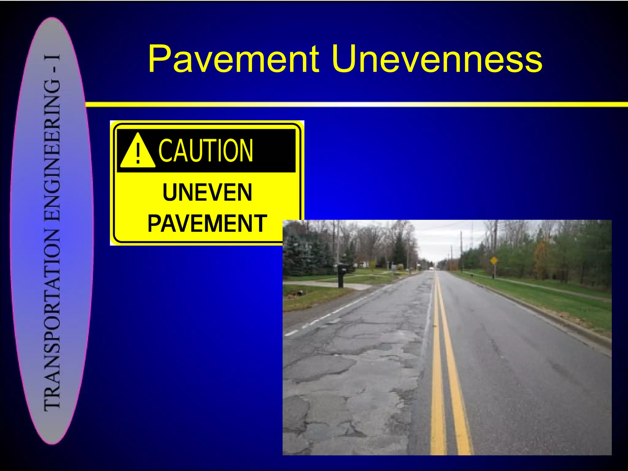
Four key aspects: friction, smoothness, light reflection, and drainage impact driving safety.Pavement unevenness' adverse effects: costs, comfort, fuel, and safety, measured by unevenness index.
Importance of road surface visibility and glare, depending on road color and material conditions.
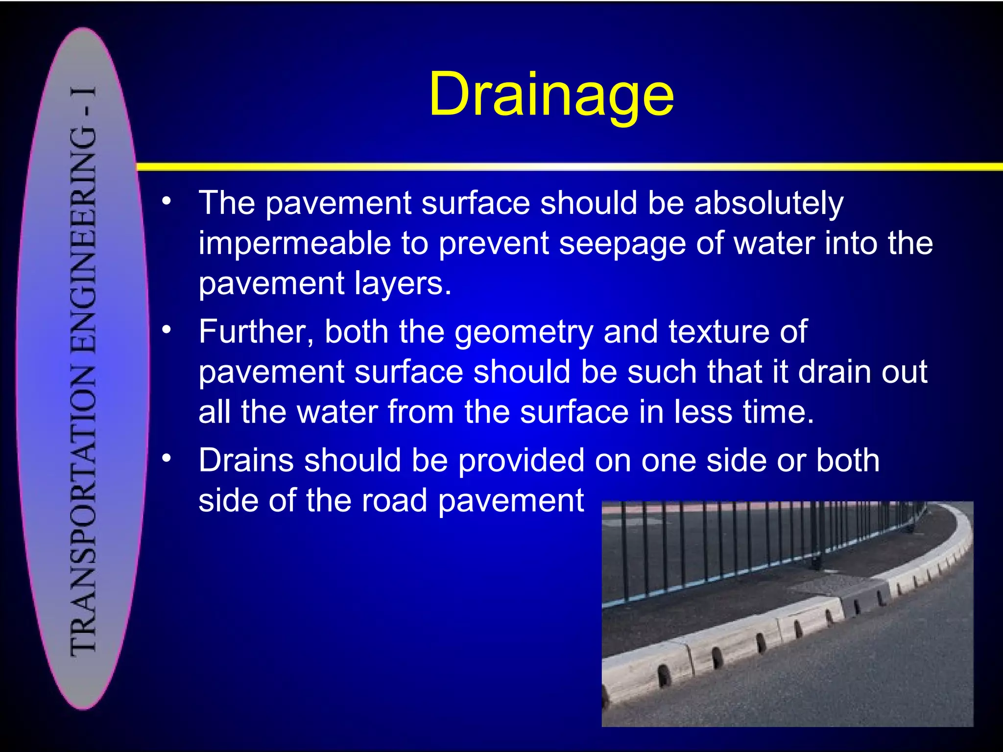
Pavement must prevent water seepage and effectively drain water, with an appropriate geometry.
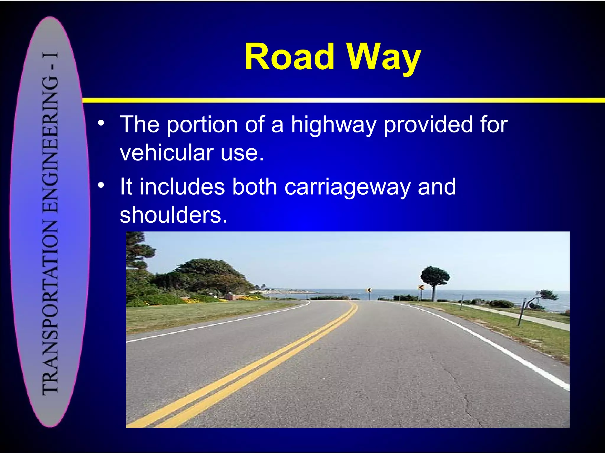
Key cross-section elements: right of way, carriageway, camber, kerbs, margins, and shoulders.
Right of way dimensions depend on road type: 2-lane (46m), 4-lane (76m), and 8-lane (91m) standards.
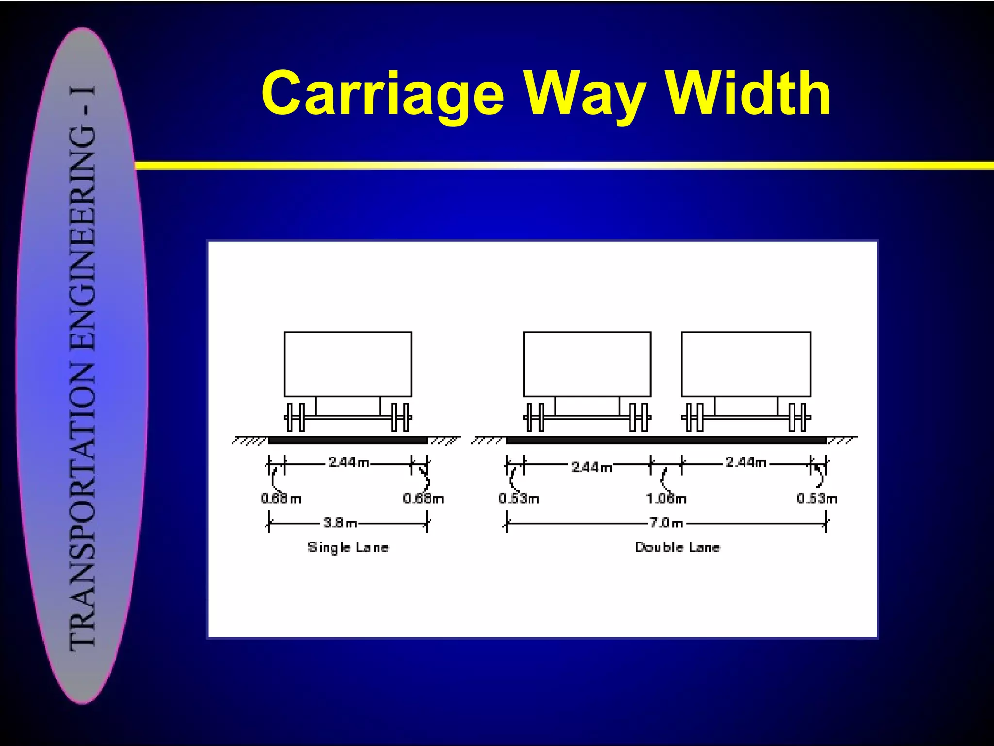
Specifications for lanes: combined width and lane counts are based on traffic volume and service level.
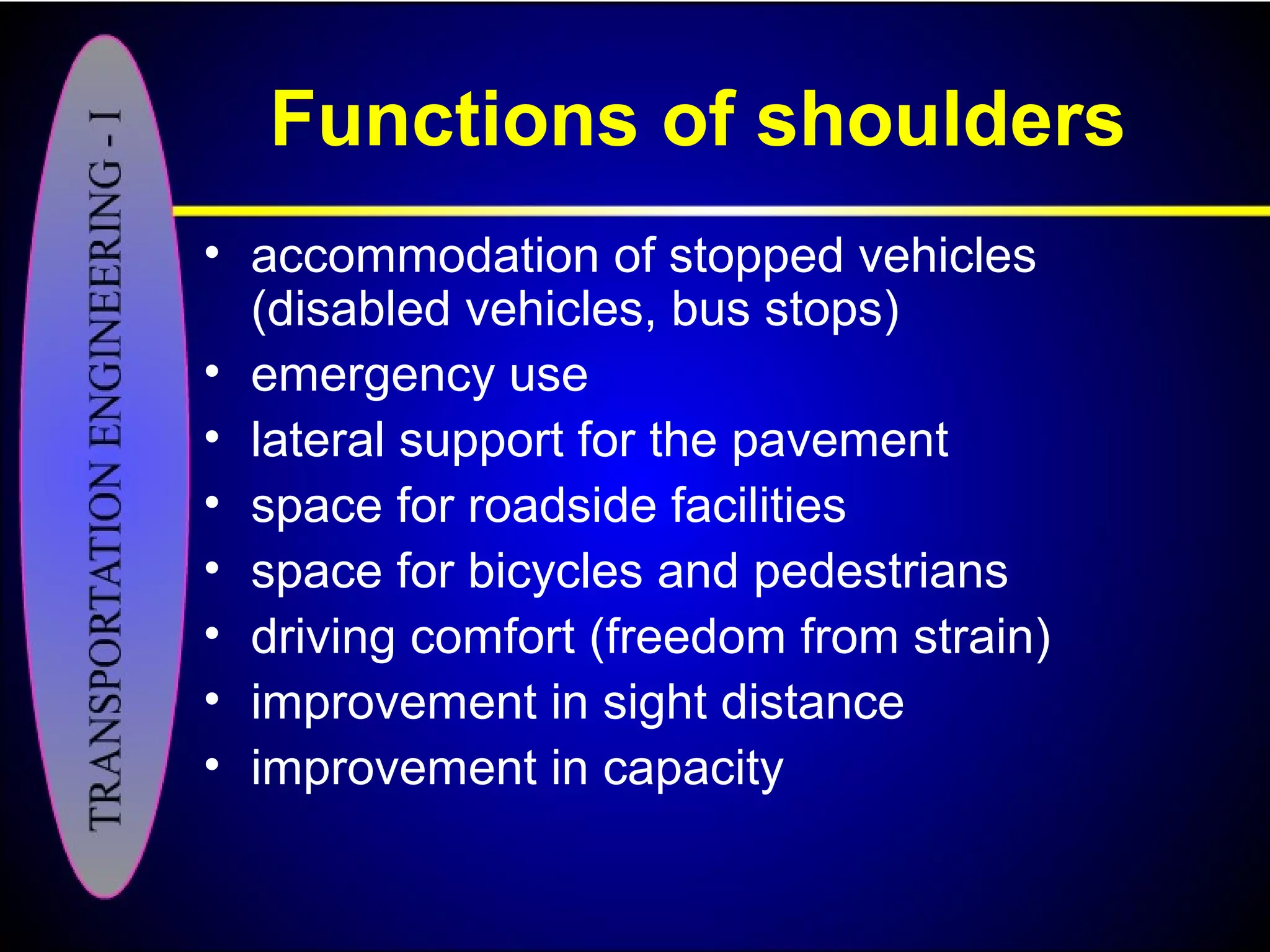
Shoulders must accommodate vehicle support, emergencies, roadside facilities, and improve sight distance.
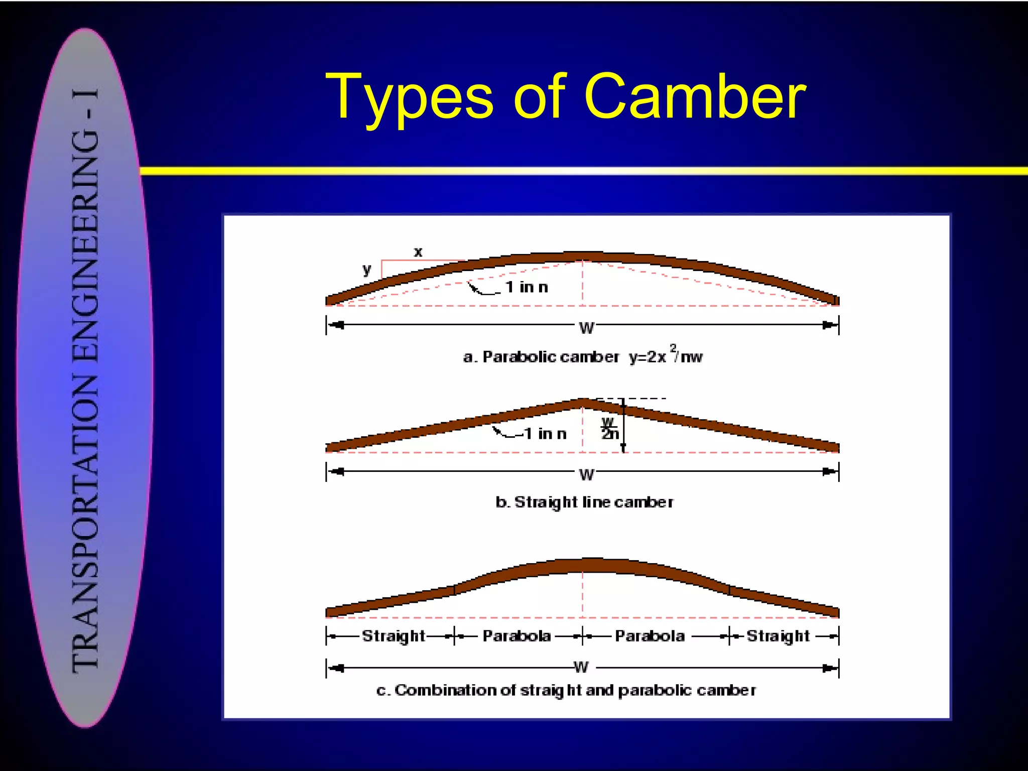
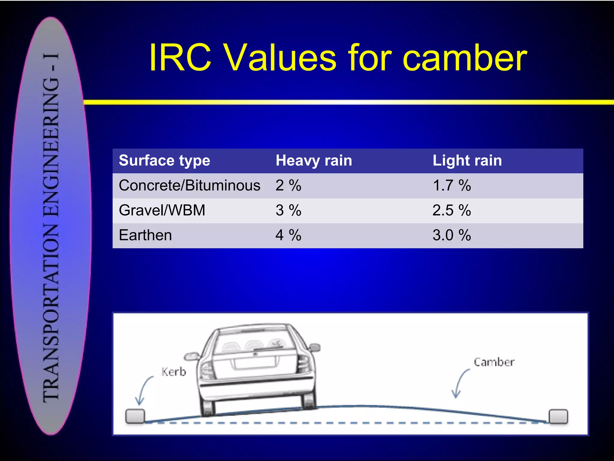
Camber is crucial for drainage; IRC recommends specific values for different surface types and rain intensities.
Kerbs delineate road edges, control drainage, and serve various practical purposes in road safety.
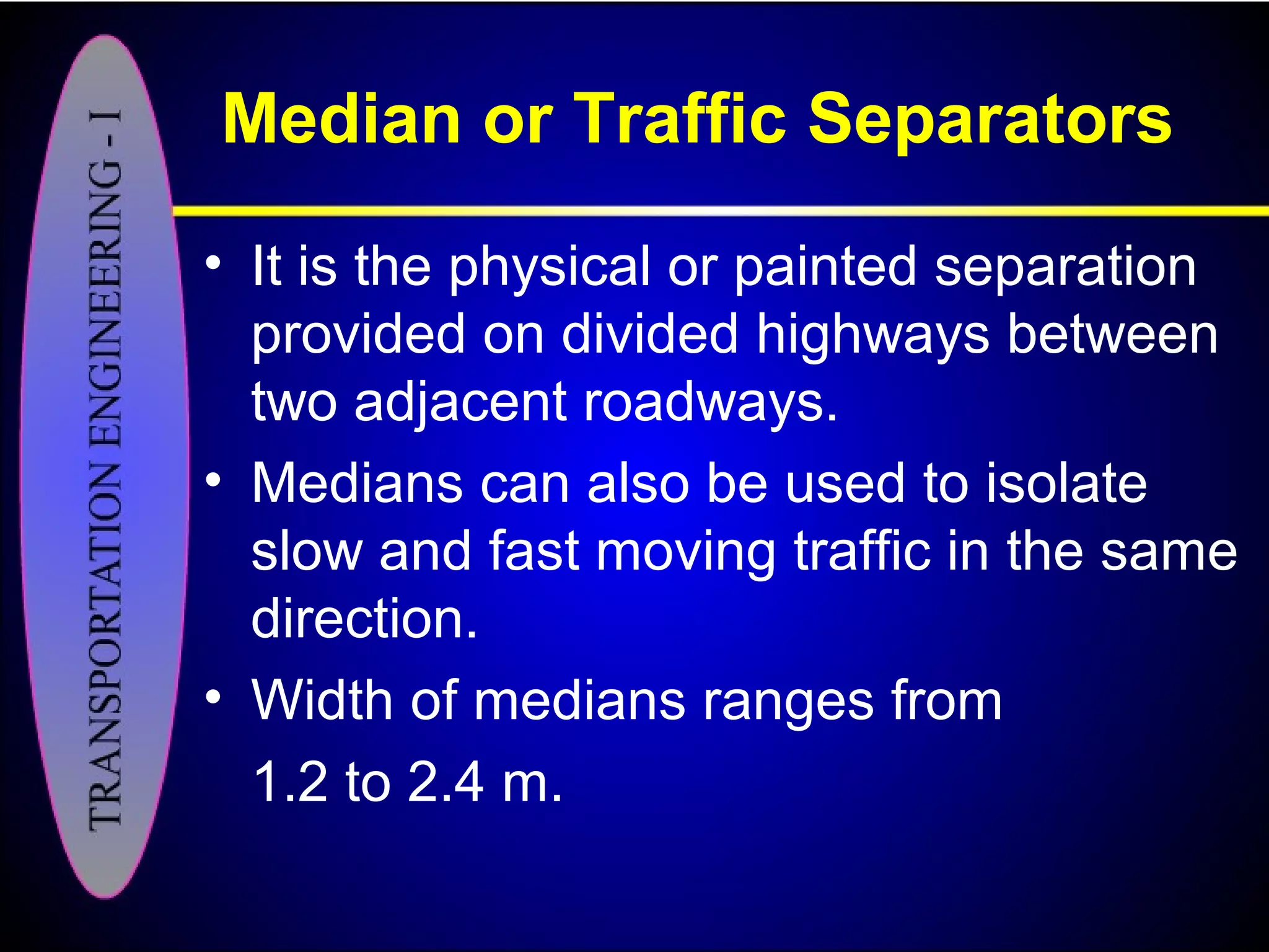
Medians separate traffic flow; widths range from 1.2 to 2.4 meters depending on the road design.
Footpaths enhance urban mobility, recommended widths are at least 1.5 meters for safety.
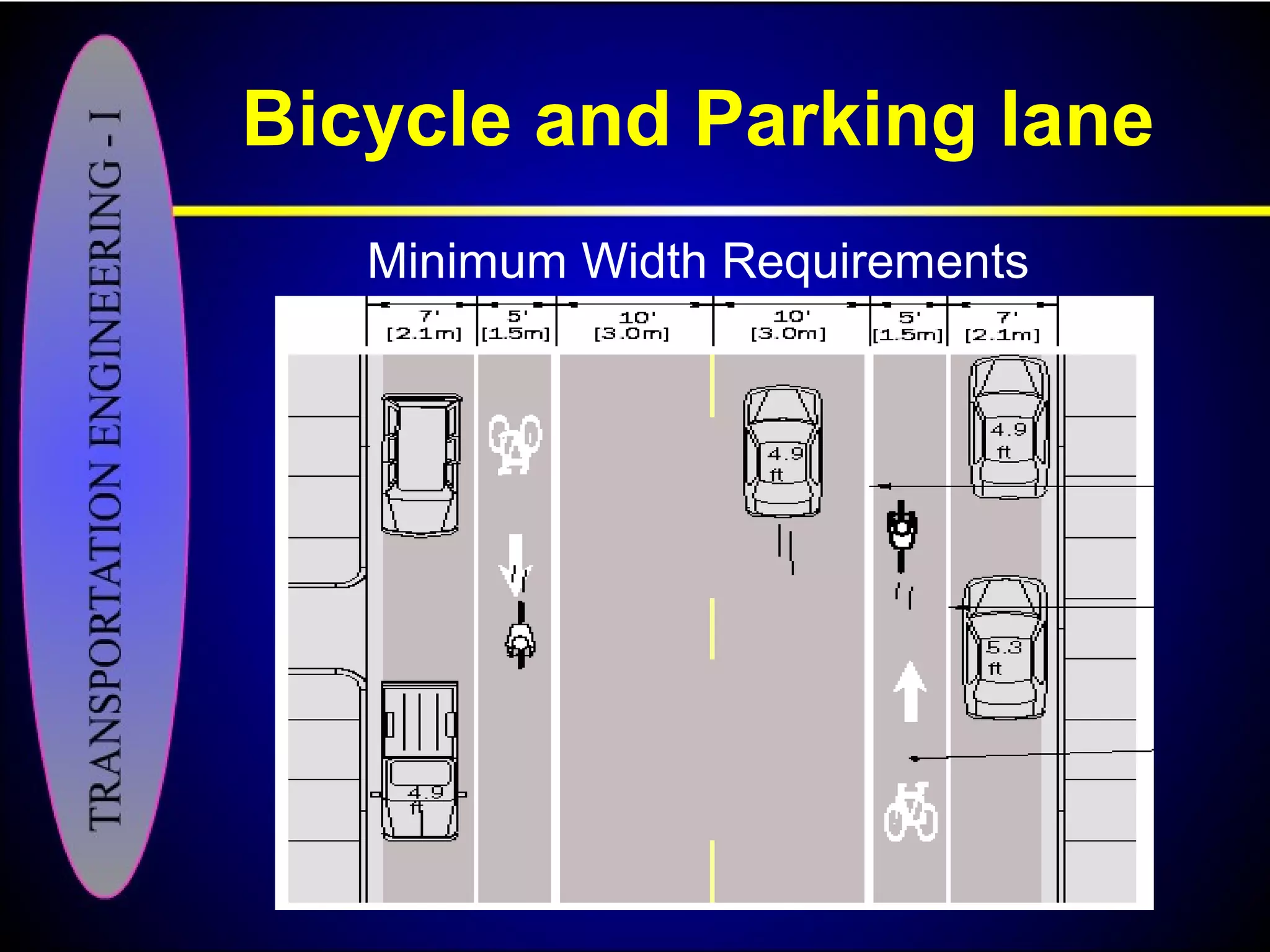
Designated lanes ensure safety for bicycles and accommodate on-street parking in urban areas.
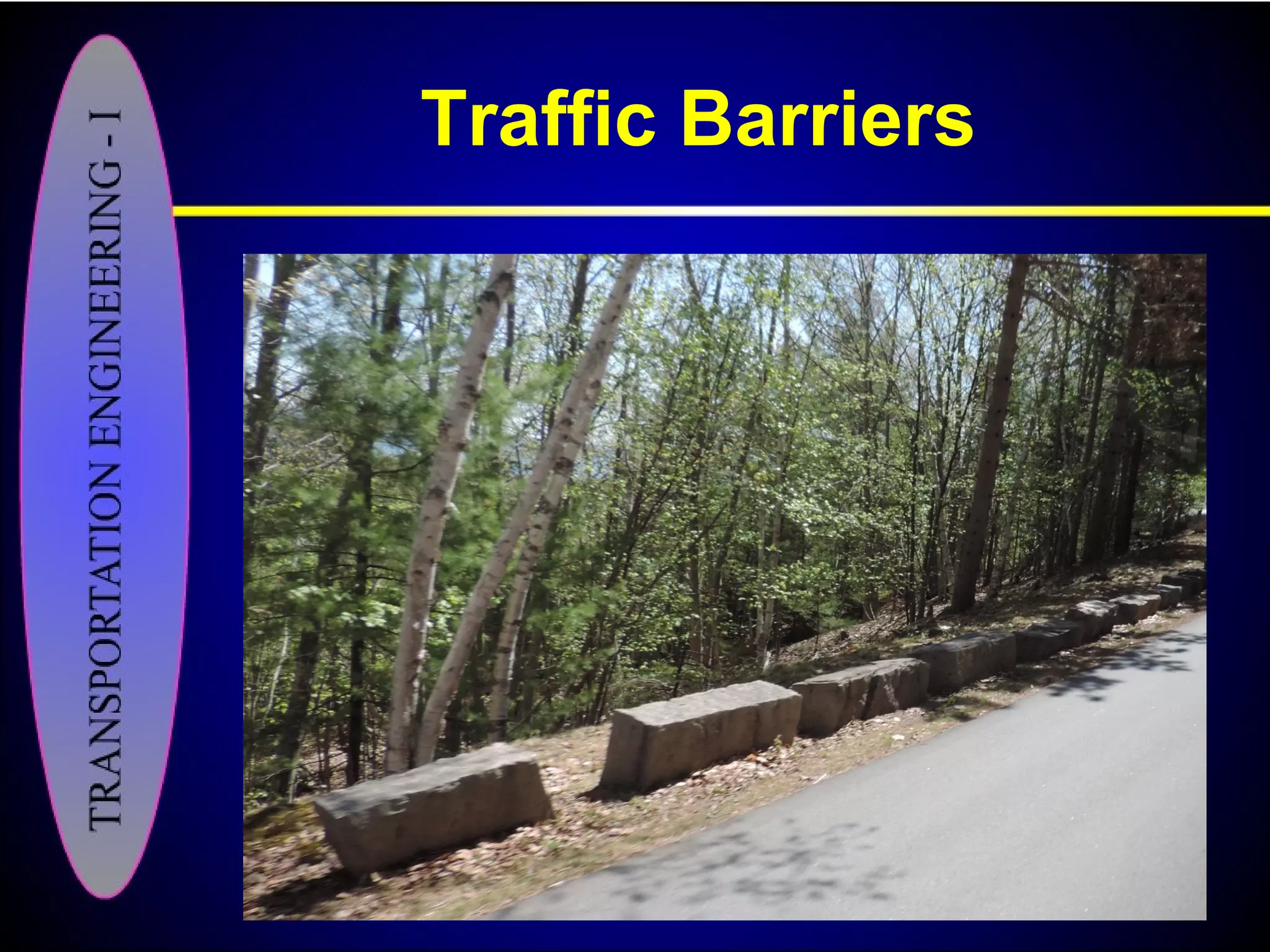
Guard rails prevent accidents at embankments, improve visibility on curves for safer driving conditions.
Bus-bays should minimize impact on traffic, ideally set away from intersections by at least 75 meters.
Introduction to highway pavement construction and materials used to support roadway structures.
Highway pavement layers distribute loads effectively while ensuring smooth travel under various conditions.
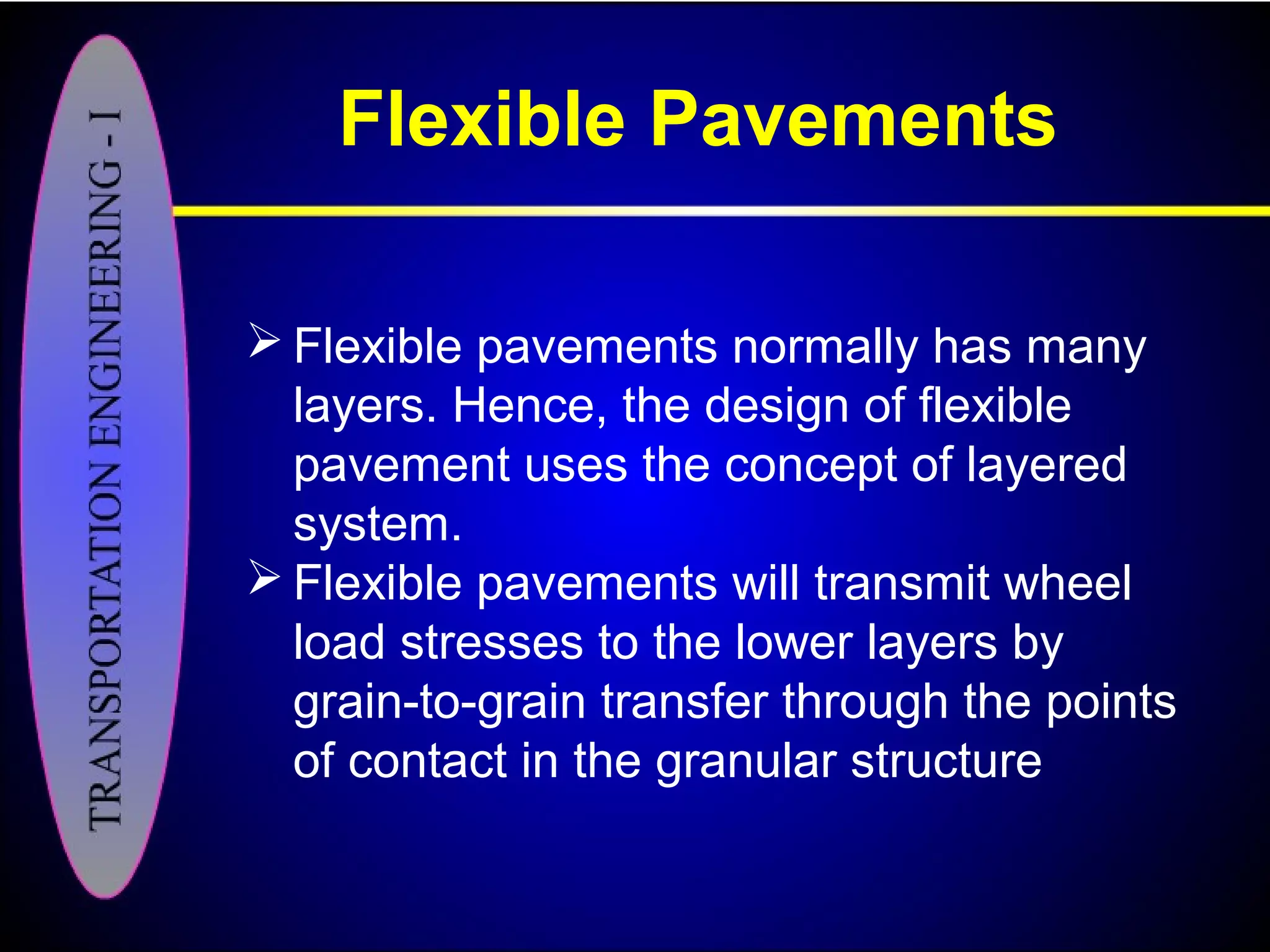
Flexible pavements characterized by layered designs that transmit loads through granular point contacts.
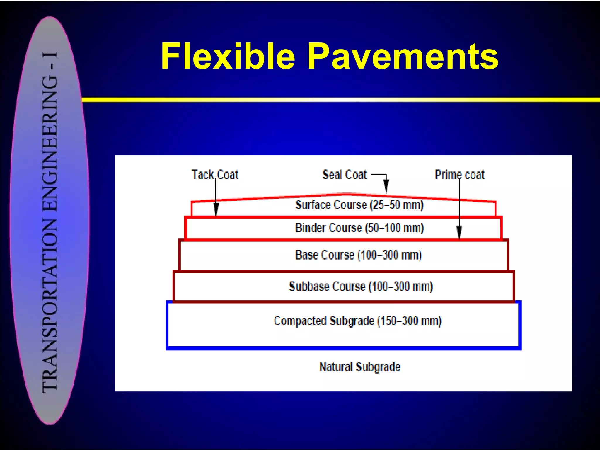
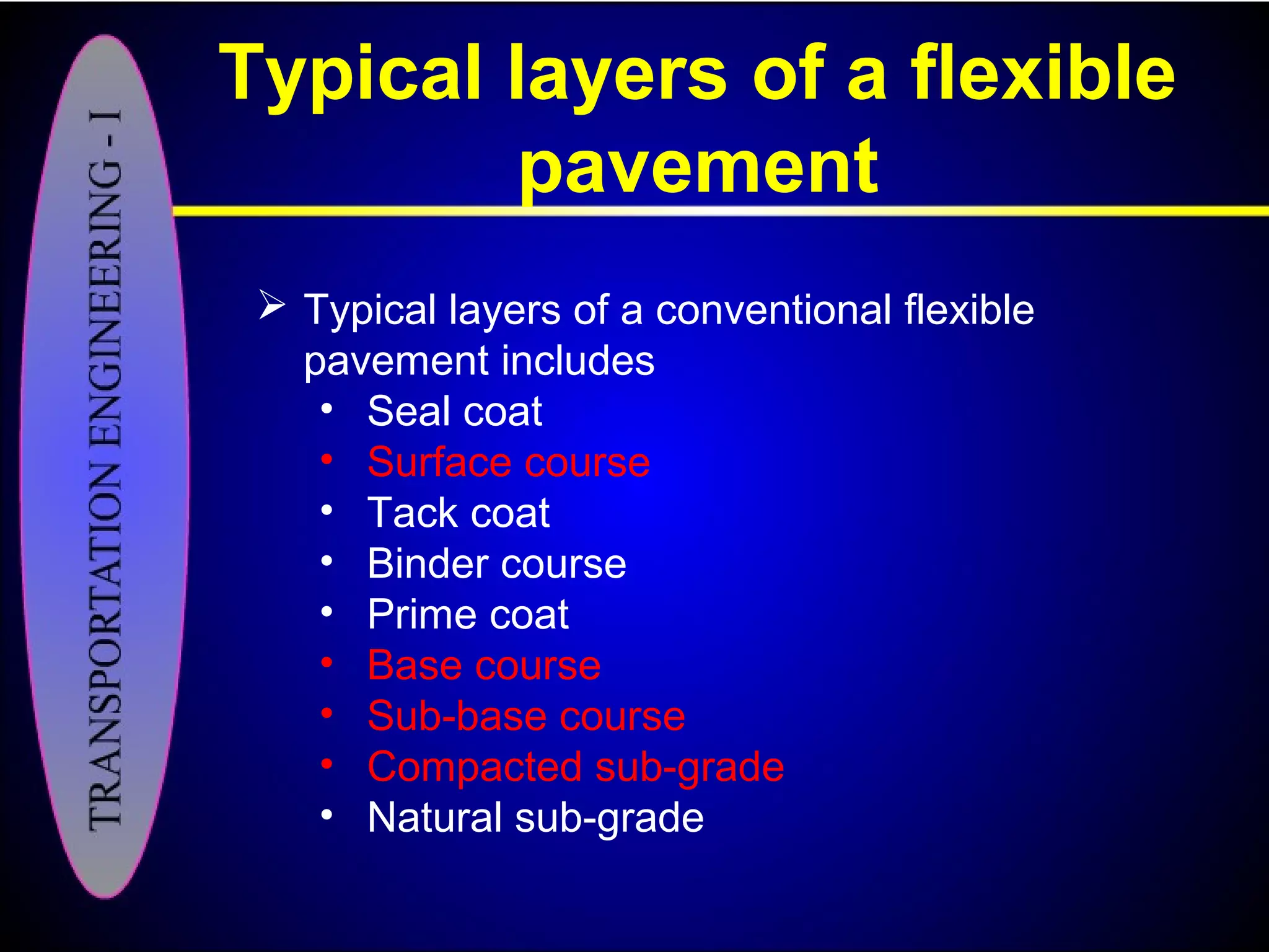
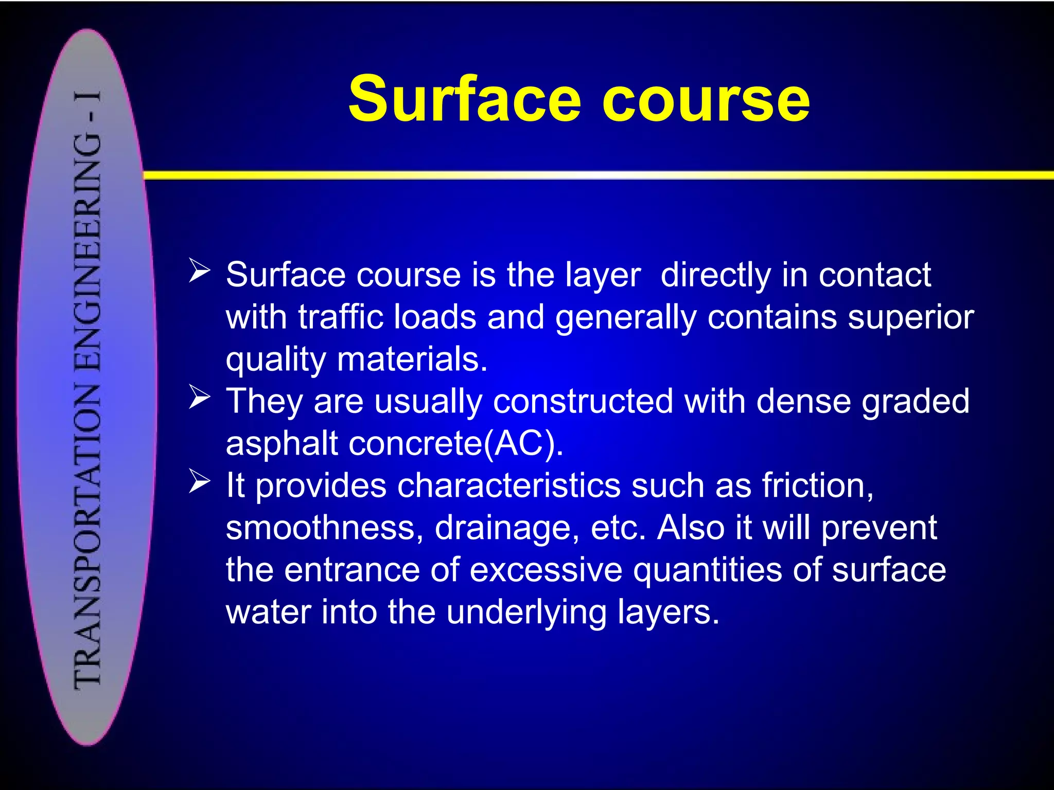
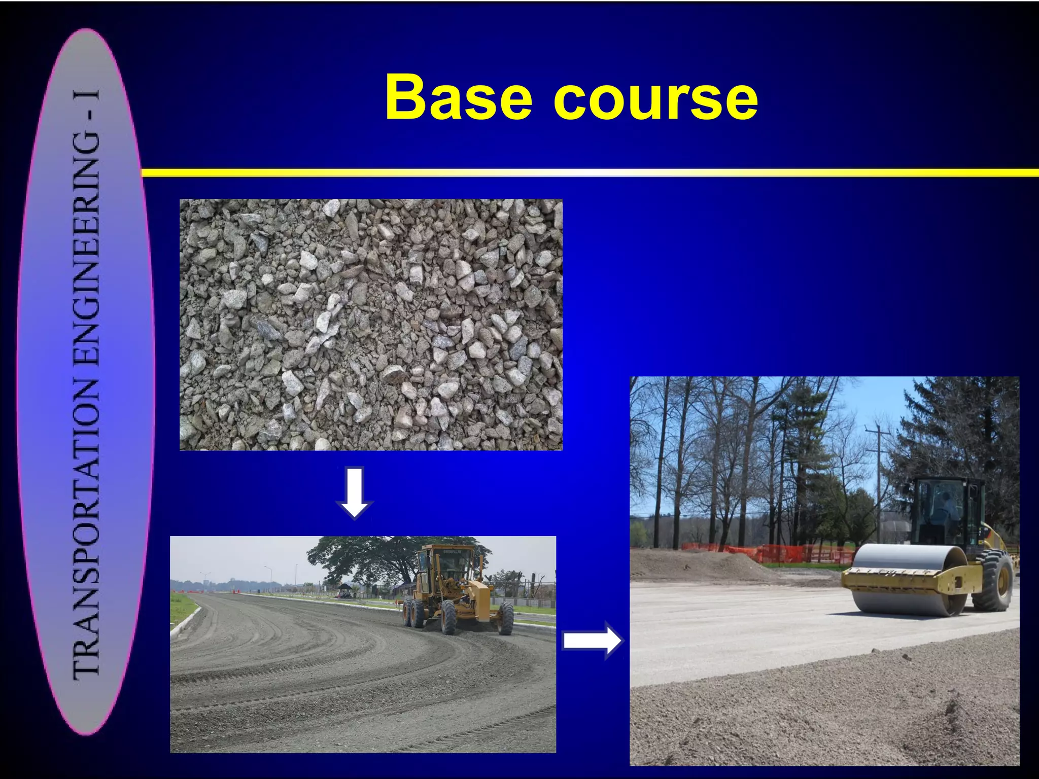
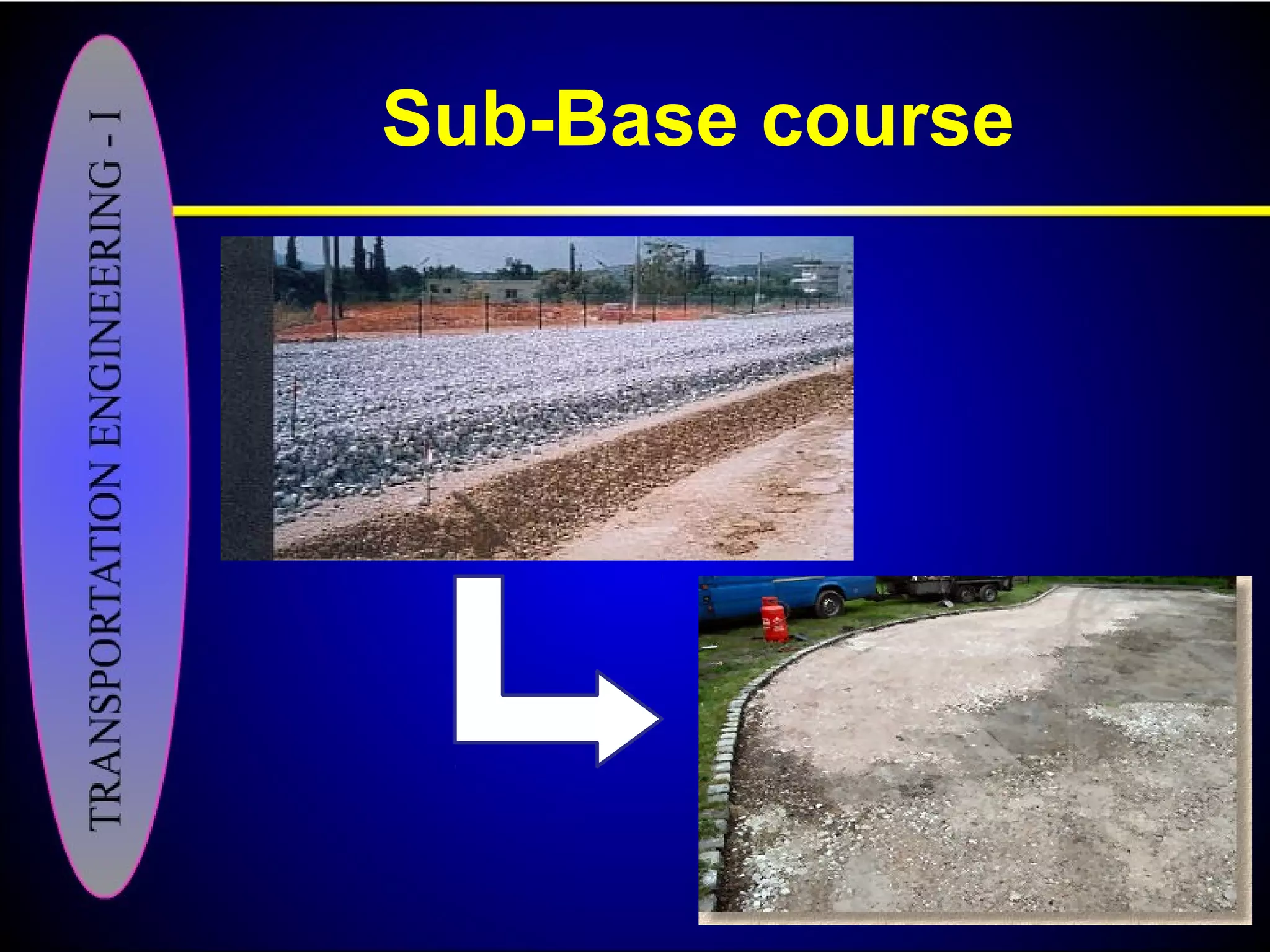
Details on pavement layers: seal coat, surface course, tack coat, binder, base, and sub-base functions.
Desirable subgrade soil properties ensure stability, drainage, and support for highway pavement structures.
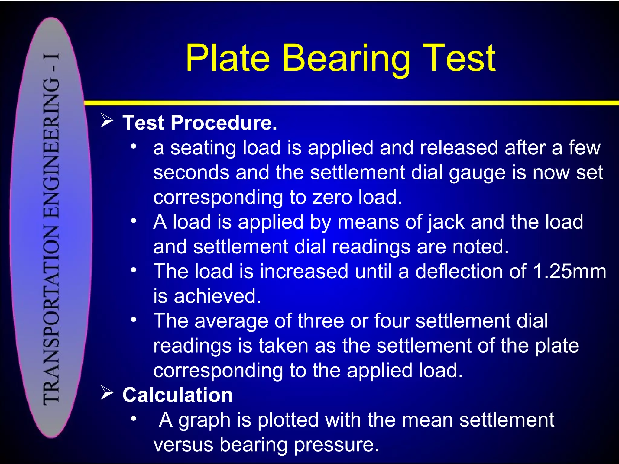
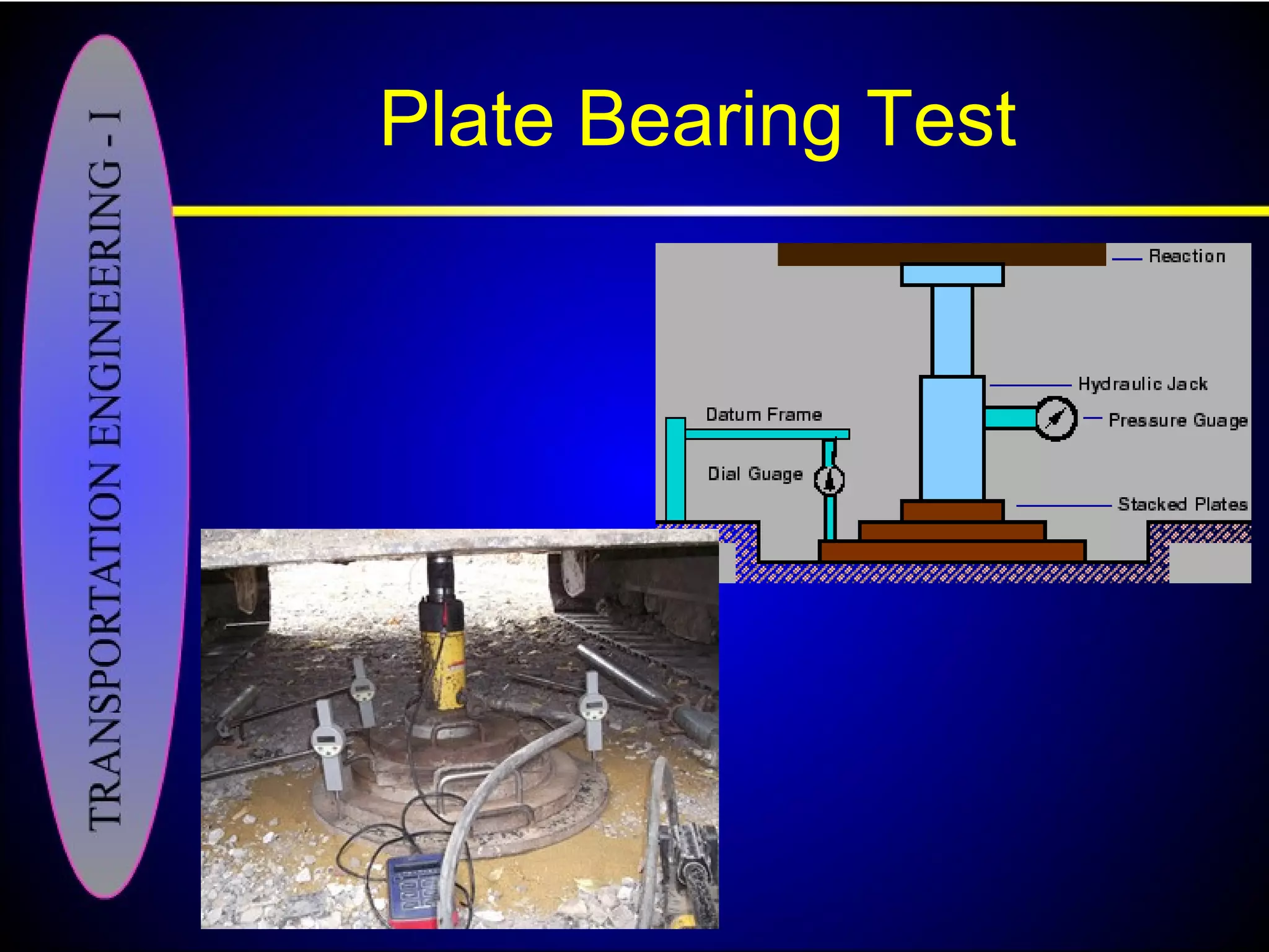
Tests to evaluate subgrade support through shear, bearing, and penetration tests are essential.
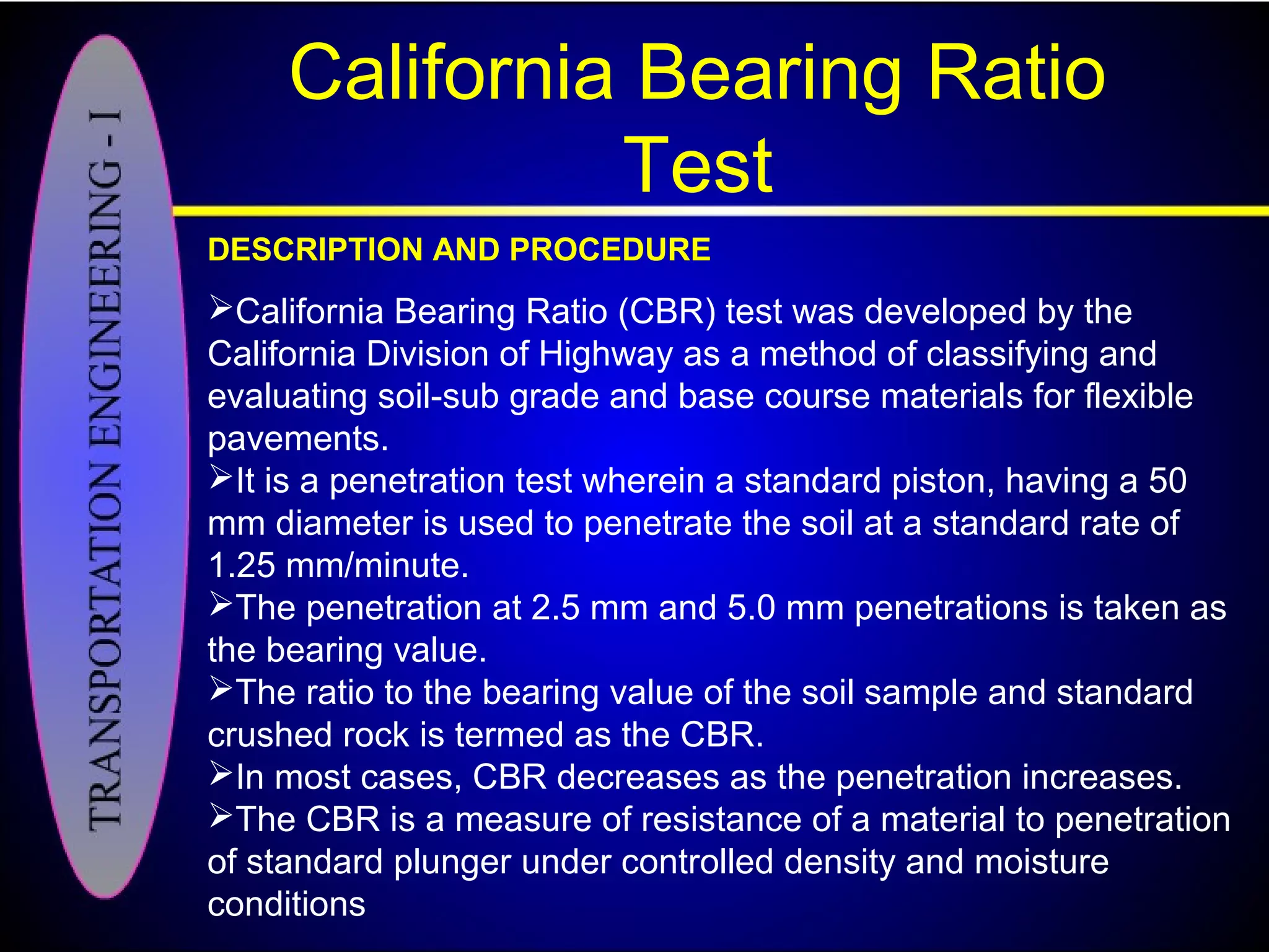
CBR test method evaluates soil-subgrade quality for flexible pavement, defines resistance against penetration.
Desirable properties of aggregates include strength, adhesion with bitumen, and durability assessment methods.
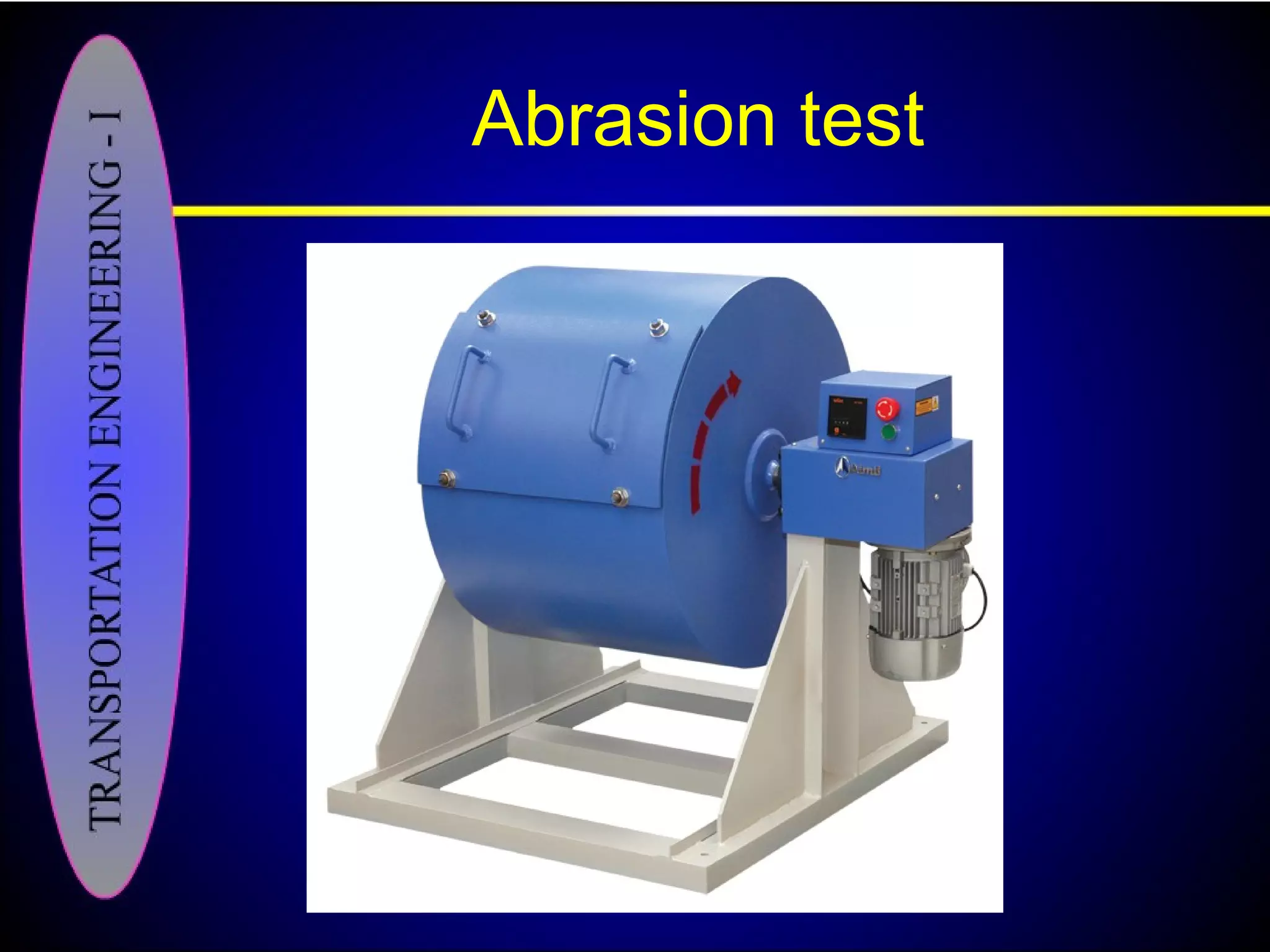
Various tests ensure aggregates' suitability, including crushing, abrasion, and impact resistance evaluations.
Bitumen serves as the main binder in pavement due to its adhesive and waterproof properties in construction.
Tests measure bitumen quality, including penetration, ductility, viscosity, and flash points for safety.
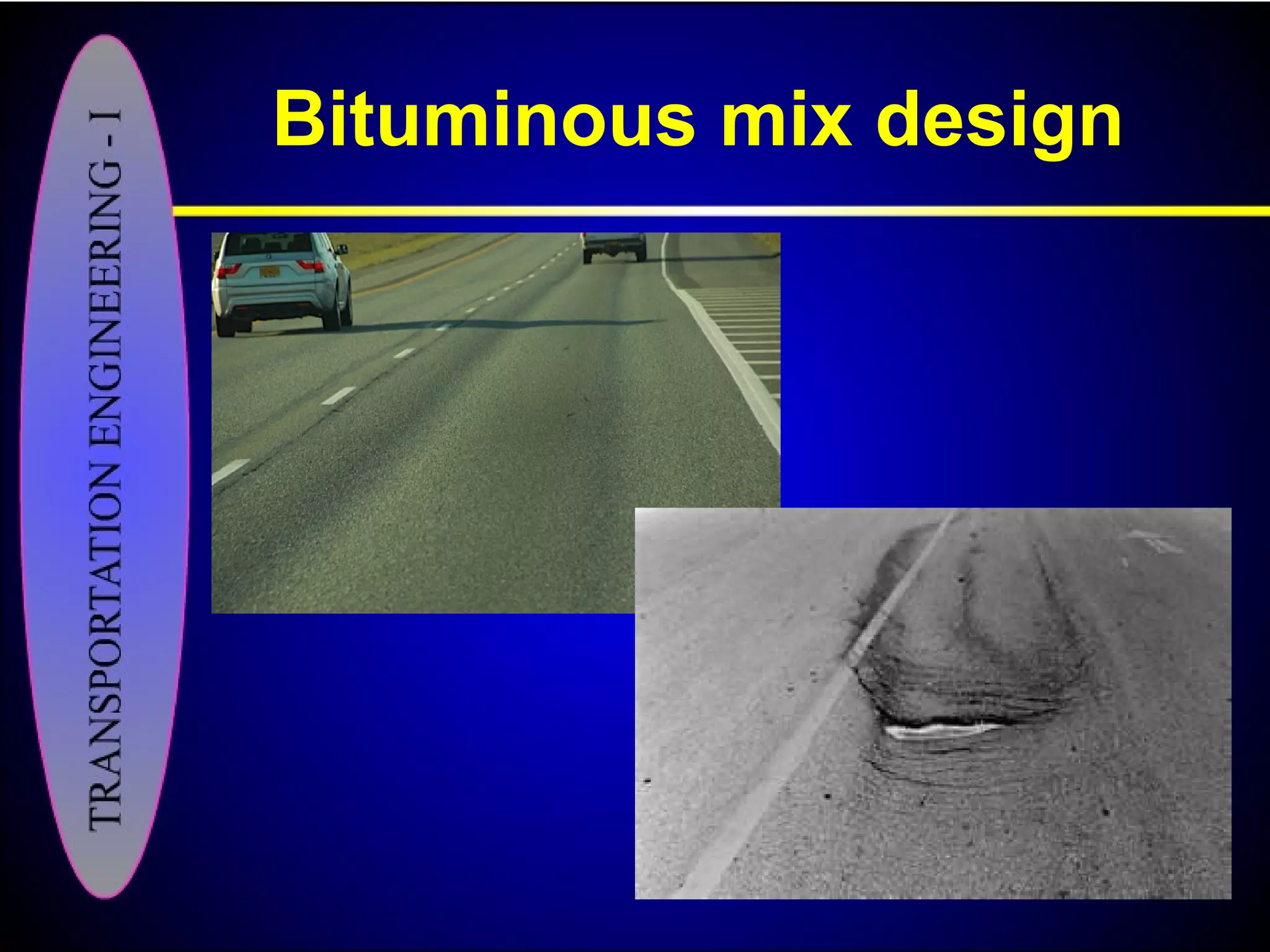
Durability, flexibility, and workability standards in mix design ensure the performance of asphalt pavements.
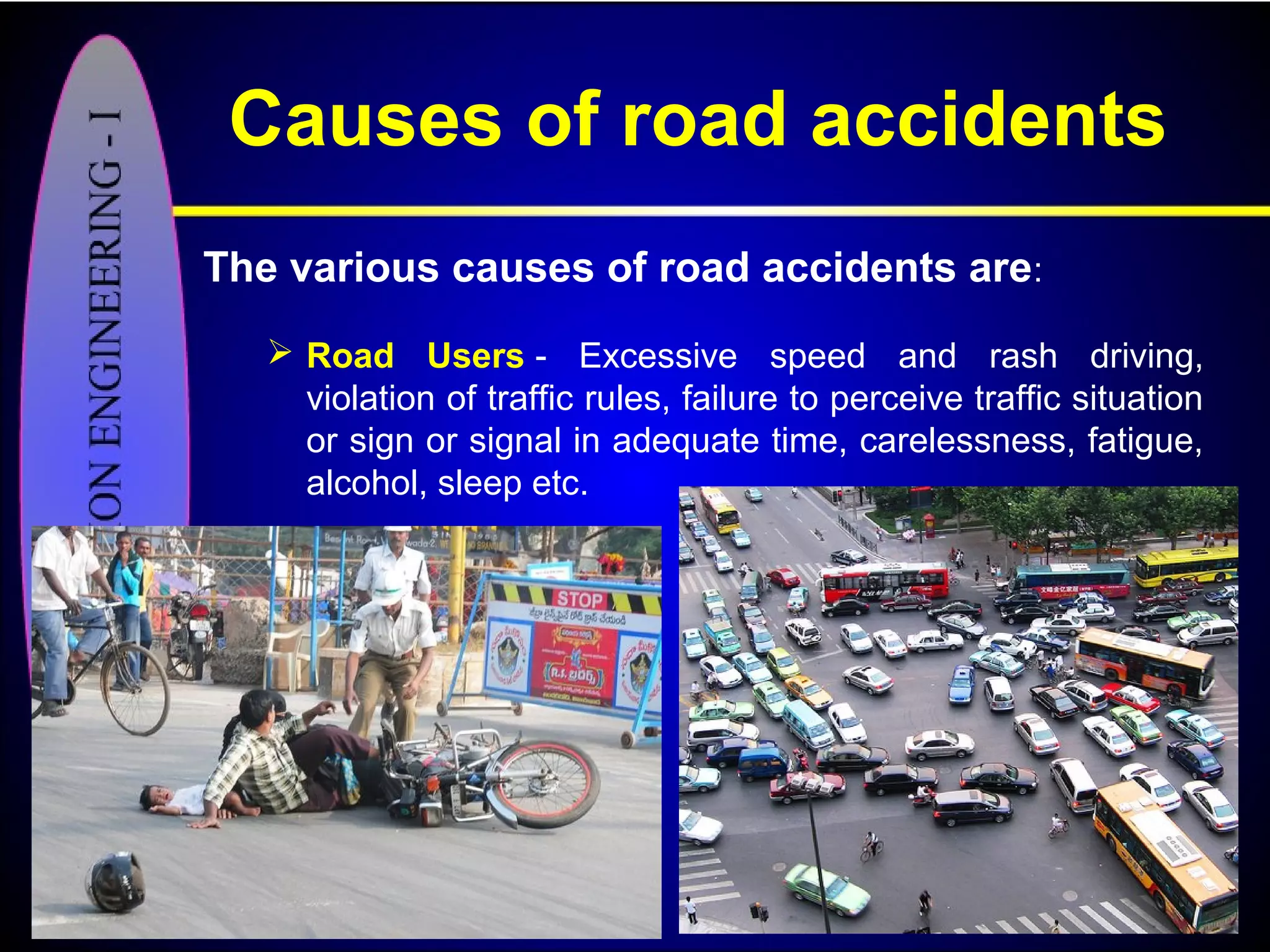
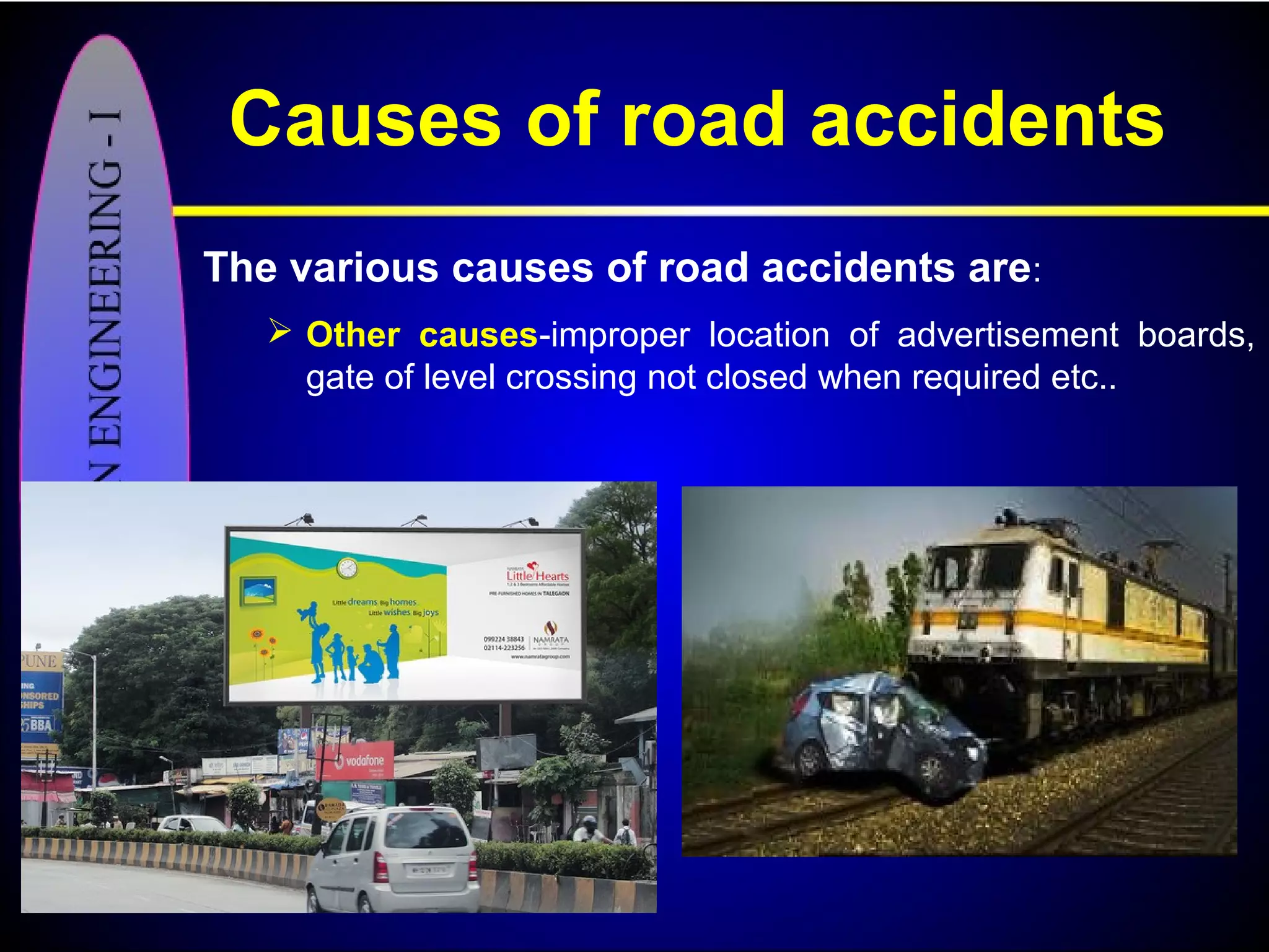
Introduction to alarming statistics on road accidents and their economic impact globally.Identifies human, vehicle, road condition, design, and environmental factors contributing to accidents.
'3-Es' strategy: Engineering, Enforcement, and Education aimed at improving safety and reducing accidents.
Elements of a
TypicalCross-section of
Road and Highway drainage
Transportation Engineering – I
Subrat Kumar Padhy
2.
Pavement surface
characteristics
• Forsafe and comfortable driving four
aspects of the pavement surface are
important.
• It includes :-
– Friction between the wheels and the pavement
surface.
– Smoothness of the road surface
– The light reflection characteristics of road.
– Drainage of water.
3.
Friction between thewheels and
the pavement surface.
• It is a crucial factor in the design of horizontal
curves.
• It affects the acceleration and deceleration ability
of vehicles
• Lack of adequate friction can cause skidding or
slipping of vehicles.
– Skidding happens when the path traveled along the
road surface is more than the circumferential movement
of the wheels due to friction.
– Slip occurs when the wheel revolves more than the
corresponding longitudinal movement along the road
4.
• Various factorsthat affect friction are:
– Type of the pavement (like bituminous, concrete, or
gravel),
– Condition of the pavement (dry or wet, hot or cold, etc),
– Condition of the tyre (new or old), and
– Speed and load of the vehicle.
• The frictional totally depends upon a factor called
the coefficient of friction and denoted as f.
– IRC suggests the coefficient of longitudinal friction as
0.35-0.4 useful in sight distance calculation.
– Coefficient of lateral friction as 0.15 useful in horizontal
curve design
Friction between the wheels and
the pavement surface.
5.
Pavement Unevenness
• Evenif a road is constructed with high quality pavers, it is
possible to develop unevenness due to pavement failures.
• Unevenness affects the vehicle operating cost, speed, riding
comfort, safety, fuel consumption and wear and tear of tyres.
• Pavement Unevenness is measured in terms of Unevenness
index.
• Unevenness index is a measure of unevenness which is the
cumulative measure of vertical undulations of the pavement
surface recorded per unit horizontal length of the road.
• An unevenness index value
– Less than 1500 mm/km - good
– Less than 2500 mm/km - satisfactory
– Greater than 3200 mm/km - uncomfortable even for speed
of 55 kmph.
Light refection characteristics
•It is necessary that the road surface should be
visible at night and reflection of light from the road
surface should be less.
• White roads have good visibility at night, but
caused glare during day time.
• Black roads has no glare during day, but has
poor visibility at night
• Concrete roads has better visibility and less
glare.
• Wet pavement surface can cause high glare.
– Glare is difficulty seeing in the presence bright light such
as direct or reflected sunlight or artificial light such as
car headlights at night.
Drainage
• The pavementsurface should be absolutely
impermeable to prevent seepage of water into the
pavement layers.
• Further, both the geometry and texture of
pavement surface should be such that it drain out
all the water from the surface in less time.
• Drains should be provided on one side or both
side of the road pavement
Cross-Section Elements
The crosssection of a road includes some
or all of the following elements:
– Right of way.
– Carriage way
– Camber or cross slope.
– Kerbs
– Road margins.
• Shoulders
• Parking lanes
• Bus-bays
• Service roads.
• Footpath.
• Guard rails
12.
Right of Way
•Right of way (ROW) or land width is the width of land acquired
for the road, along its alignment.
• It should be adequate to accommodate all the cross-sectional
elements of the highway and may reasonably provide for
future development.
• The width of right of way is governed by:
– Width of formation of road.
– Height of embankment or depth of cutting
– Side slopes of embankment or cutting
– Drainage system
– Sight distance considerations
– Reserve land for future widening
• According to IRC normal width of ROW
– For 2 lane road = 150 ft width of area (46m)
– For 4 lane road = 250 ft width of area (76m)
– For 8 lane road = 300 ft width of area (91m)
Traveled Way orCarriage Way
• The portion of the roadway provided for the
movement of vehicles, exclusive of shoulders.
• Number of lanes on a traveled way are decided on
the basis of expected traffic volumes and appropriate
level of service required for the facility.
• Width of a lane depends on the width of the vehicle
and the clearance needed.
• According to IRC
– Minimum of lane width of 3.75 m - Single lane road.
– Two lane road require minimum of 3.5 meter for each lane
total 7m for both lane.
Road Way
• Theportion of a highway provided for
vehicular use.
• It includes both carriageway and
shoulders.
17.
Shoulders
• Shoulders arethe strips provided on both sides of
the carriage way.
• A minimum width of 2.5 m is recommended for 2-
lane highways in India. (max 4.5m)
18.
Functions of shoulders
•accommodation of stopped vehicles
(disabled vehicles, bus stops)
• emergency use
• lateral support for the pavement
• space for roadside facilities
• space for bicycles and pedestrians
• driving comfort (freedom from strain)
• improvement in sight distance
• improvement in capacity
19.
Camber
• Camber isthe cross slope provided to raise middle
of the road surface in the transverse direction to
drain off rain water from road surface.
• Too steep slope is undesirable for it will erode the
surface.
• Camber is measured in 1 in n or n% (Eg. 1 in 50 or
2%)
• The objectives of providing camber are:
– Surface protection especially for gravel and bituminous
roads
– Sub-grade protection by proper drainage.
– Quick drying of pavement which in turn increases safety.
Kerb
• It isthe dividing line between carriageway
and footpath.
23.
Types of Kerbs
•Low or mountable kerbs:
– Height of 10 cm above the pavement edge.
– With a slope which allows the vehicle to climb over easily
• Semi-barrier type kerbs
– Height is 15 cm above the pavement edge.
– parking vehicles, but at emergency only.
• Barrier type kerbs.
– Height of 20 cm above the pavement edge
– With a steep slope.
• Submerged kerb.
– Provide lateral stability
Functions of Kerbs
•Drainage control
• Roadway edge delineation
• Right-of-way reduction
• Delineation of pedestrian walkways
• Reduction in maintenance operation
• Assistance in roadside development
26.
Median or TrafficSeparators
• It is the physical or painted separation
provided on divided highways between
two adjacent roadways.
• Medians can also be used to isolate
slow and fast moving traffic in the same
direction.
• Width of medians ranges from
1.2 to 2.4 m.
Foot Path orside Walk
• Foot paths are provided in Urban
roads
• These are raised strips constructed
along both the edges of roads.
• Their minimum recommended width
is 1.5 m.
Bicycle and Parkinglane
• Bicycle lane is a portion of the
roadway designated by striping,
signing, and/or pavement markings
for preferential or exclusive use by
bicycles and/or other non-motorized
vehicles.
• Parking lane is an additional lane
provided on Urban roads and streets
for on-street parking.
Traffic Barriers orGuard rails
• They are provided at the edge of the
shoulder usually when the road is on an
embankment.
• They serve to prevent the vehicles from
running o the embankment, especially
when the height exceeds 3 m.
• Guard rails of stones painted in alternate
black and white are usually used.
• They also give better visibility of curves at
night under headlights of vehicles.
Bus-bays
• Bus baysare provided by recessing
the kerbs for bus stops.
• They are provided so that they do not
obstruct the movement of vehicles in
the carriage way.
• They should be at least 75 meters
away from the intersection so that the
traffic near the intersections is not
affected by the bus-bay.
Pavements
Highway pavementis a structure consistingHighway pavement is a structure consisting
layers of processed materials above thelayers of processed materials above the
natural soil sub-grade, whose primarynatural soil sub-grade, whose primary
function is to distribute the applied vehiclefunction is to distribute the applied vehicle
loads to the sub-grade.loads to the sub-grade.
The pavement structure should be able toThe pavement structure should be able to
provide a surface with adequate skidprovide a surface with adequate skid
resistance, favourable light reflectingresistance, favourable light reflecting
characteristics, and low noise pollution.characteristics, and low noise pollution.
Two types of pavements
• Flexible pavements
• Rigid pavements.
Flexible Pavements
Flexiblepavements normally has many
layers. Hence, the design of flexible
pavement uses the concept of layered
system.
Flexible pavements will transmit wheel
load stresses to the lower layers by
grain-to-grain transfer through the points
of contact in the granular structure
Typical layers ofa flexible
pavement
Typical layers of a conventional flexible
pavement includes
• Seal coat
• Surface course
• Tack coat
• Binder course
• Prime coat
• Base course
• Sub-base course
• Compacted sub-grade
• Natural sub-grade
48.
Sealcoat
Sealcoat isa liquid that is applied to asphalt
to protect it from oxidation and the damage
caused by winter cracking, as well as UV rays
and traffic.
In areas of the world that experience freezing
and thawing, this special coat is applied.
49.
Surface course
Surfacecourse is the layer directly in contact
with traffic loads and generally contains superior
quality materials.
They are usually constructed with dense graded
asphalt concrete(AC).
It provides characteristics such as friction,
smoothness, drainage, etc. Also it will prevent
the entrance of excessive quantities of surface
water into the underlying layers.
50.
Tack coat
Itis a thin coating of tar or asphalt applied before
a roads surface course is laid to form an adhesive
bond.
It must be thin, uniformly cover the entire surface,
and set very fast.
51.
Binder course
Inasphaltic concrete paving, an intermediate
course between the base course and the
surfacing material is present called binder course.
It consists of intermediate-size aggregate bound
by bituminous material.
52.
Prime coat
Prime coatis an application of a low viscosity
asphalt to a granular base in preparation for an
initial layer (or surface course layer) of asphalt.
It is generally
• Provide adhesion between the base course and
succeeding asphalt course.
• It penetrates into the layer below, plugs the voids, and
forms a water tight surface.
After applying the prime coat, it must cure for a
minimum of 48-72 hours before asphalt is placed,
with no rain in the forecast
Base course
Thebase course is the layer of material
immediately beneath the surface of binder
course.
It provides additional load distribution and
contributes to the sub-surface drainage
It may be composed of crushed stone, crushed
slag, and other untreated or stabilized
materials.
Sub-Base course
Thesub-base course is the layer of material
beneath the base course
primary functions are to provide structural
support, improve drainage, and reduce the
intrusion of fines from the sub-grade.
A sub-base course is not always needed or
used. For example, a pavement constructed over
a high quality materials, In such situations, sub-
base course may not be provided.
Sub grade soil
The supporting soil beneath pavement and its
special under courses is called sub grade.
Undisturbed soil beneath the pavement is
called natural sub grade.
Compacted sub grade is the soil compacted by
controlled movement of heavy compactors.
59.
Desirable properties
Thedesirable properties of sub grade soil as a
highway material are
• Stability
• Incompressibility
• Permanency of strength
• Minimum changes in volume and stability
under adverse conditions of weather and
ground water
• Good drainage
• Ease of compaction
60.
Soil Types
Thewide range of soil types available as
highway construction materials have made it
obligatory on the part of the highway engineer to
identify and classify different soils.
Broadly, the soil types can be categorized as
Laterite soil, Moorum/red soil, Sandy soil,
Alluvial soil, Clay including Black cotton soil.
61.
Soil Types
Gravel:These are coarse materials with particle size under
2.36 mm with little or no fines contributing to cohesion of
materials.
Moorum: These are products of decomposition and
weathering of the pavement rock. Visually these are similar
to gravel except presence of higher content of fines.
Sand : Sand is a naturally occurring granular material
composed of finely divided rock and mineral particles. It is
defined by size, being finer than gravel and coarser than silt.
Silts: These are finer than sand, brighter in color as
compared to clay, exhibit little cohesion and show dilatancy.
Clays: These are finer than silts. Clayey soils exhibit
stickiness, high strength when dry, and show no dilatancy.
• Black cotton soil and other expansive clays exhibit swelling and
shrinkage properties. Paste of clay with water when rubbed in
between fingers leaves stain, which is not observed for silts.
Tests on sub-gradesoil
The main function of the sub grade is to give
adequate support to the pavement.
For this the sub grade should possess sufficient
stability under adverse climatic and loading
conditions. Therefore, it is very essential to evaluate
the sub grade by conducting tests.
The tests used to evaluate the strength properties of
soils are of 3 types.
• Shear tests
• Bearing tests
• Penetration tests
64.
Direct Shear Test
CONCEPT
TheDirect Shear Test is used for determination of the consolidated
drained (or undrained) shear strength of soils.
The test is performed by deforming a specimen at a controlled rate on
or near a single shear plane.
DESCRIPTION AND PROCEDURE
The soil sample is placed in a cubic shear box composed of a upper
and lower box.
The limit between the two parts of the box is approximately at the mid
height of the sample.
The sample is subjected to a controlled normal stress and the upper
part of the sample is pulled laterally at a controlled strain rate or until the
sample fails.
The applied lateral load and the induced strain are recorded at given
internals.
These measurements are then used to plot the stress-strain curve of
the sample during the loading for the given normal stress.
Plate Bearing Test
CONCEPT
Inplate bearing test, a compressive stress is applied
to the soil or pavement layer through rigid plates
relatively large size and the defections are measured for
various stress values.
The plate-bearing test was originally meant to find the
modulus of sub grade reaction.
DESCRIPTION AND PROCEDURE
The setup consists of
• Plates of 75,60,45 and 30 cm diameter.
• Proving ring arrangement.
• Hydraulic jack
• Reaction frame
• Datum frame loaded with dial gauges.
67.
Plate Bearing Test
DESCRIPTIONAND PROCEDURE
Modulus of sub grade reaction
• It can be defined as the pressure sustained per
unit deformation of subgrade soil at a specified
pressure level.
• It is directly calculated as the load imposed upon
the plate(75 cm) to achieve a deflection of
1.25mm.
• This give a value in N/mm2/mm or N/mm3.
Test Procedure.
• The test site is prepared and loose material is
removed so that the 75 cm diameter plate rests
horizontally in full contact with the soil sub-grade.
68.
Plate Bearing Test
Test Procedure.
• a seating load is applied and released after a few
seconds and the settlement dial gauge is now set
corresponding to zero load.
• A load is applied by means of jack and the load
and settlement dial readings are noted.
• The load is increased until a deflection of 1.25mm
is achieved.
• The average of three or four settlement dial
readings is taken as the settlement of the plate
corresponding to the applied load.
Calculation
• A graph is plotted with the mean settlement
versus bearing pressure.
California Bearing Ratio
Test
DESCRIPTIONAND PROCEDURE
California Bearing Ratio (CBR) test was developed by the
California Division of Highway as a method of classifying and
evaluating soil-sub grade and base course materials for flexible
pavements.
It is a penetration test wherein a standard piston, having a 50
mm diameter is used to penetrate the soil at a standard rate of
1.25 mm/minute.
The penetration at 2.5 mm and 5.0 mm penetrations is taken as
the bearing value.
The ratio to the bearing value of the soil sample and standard
crushed rock is termed as the CBR.
In most cases, CBR decreases as the penetration increases.
The CBR is a measure of resistance of a material to penetration
of standard plunger under controlled density and moisture
conditions
71.
California Bearing Ratio
Test
TestProcedure
The laboratory CBR apparatus consists of a mould 150 mm
diameter with a base plate and a collar, a loading frame and dial
gauges for measuring the penetration values and the expansion
on soaking.
The specimen in the mould is soaked in water for four days and
the swelling and water absorption values are noted.
The mould and the assembly is placed under the plunger of the
loading frame.
Load is applied on the sample by a standard plunger with dia of
50 mm at the rate of 1.25 mm/min.
A load penetration curve is drawn.
The load values on standard crushed stones are 1370 kg and
2055 kg at 2.5 mm and 5.0 mm penetrations respectively.
CBR value is expressed as a percentage of the actual load
causing the penetrations of 2.5 mm or 5.0 mm to the standard
loads mentioned above.
Aggregates
Aggregate is acollective term for the mineral
materials such as sand, gravel, and crushed stone
that are used in the construction of a pavement.
DESIRABLE PROPERTIES
Strength
Hardness
Toughness
Shape of aggregates
Adhesion with bitumen
Durability
Freedom from deleterious particles
75.
Aggregates tests
To decidethe suitability of the aggregate for use in
pavement construction, following tests are carried out.
Crushing test
Abrasion test
Impact test
Soundness test
Shape test
Specific gravity and water absorption test
Bitumen adhesion test
76.
Aggregate Crushing Test
This test is used to determine the crushing strength of
aggregates
The aggregate crushing value provides a relative measure of
resistance to crushing under gradually applied crushing load.
Test Procedure
Dry aggregates passing through 12.5 mm sieves and retained
10 mm sieves are taken as test sample.
The test sample is weighed and placed in the test cylinder of
11.5 mm diameter and 18 cm height in three layers each layer
being tampered 25 times.
The specimen is subjected to a compressive load of 40 tonnes
gradually applied at the rate of 4 tones per minute.
Then crushed aggregates are then sieved through 2.36 mm
sieve and weight of passing material (W2) is expressed as
percentage of the weight of the total sample (W1) which is the
aggregate crushing value.
77.
Aggregate Crushing Test
CALCULATION
Aggregatecrushing value = (W2/W1) x
100.
A value less than 10 signifies an exceptionally strong
aggregate while above 35 would normally be regarded as
weak aggregates.
78.
Abrasion test
DESCRIPTION ANDPROCEDURE
Abrasion test is carried out to test the hardness
property of aggregates and to decide whether they are
suitable for different pavement construction works.
Los Angeles abrasion test is a preferred one for
carrying out the hardness property and has been
standardized in India.
The principle of Los Angeles abrasion test is to find
the percentage wear due to relative rubbing action
between the aggregate and steel balls used as
abrasive charge.
79.
Abrasion test
Test Procedure
LosAngeles machine consists of
Circular drum
• internal diameter 700 mm
• length 520
An abrasive charge (cast iron spherical balls)
• 48 mm diameters
• weight 340-445 g
Charge is placed in the cylinder along with the aggregates.
The quantity of aggregates to be used depends upon the
gradation and usually ranges from 5-10 kg.
The cylinder is then locked and rotated at the speed of 30-33
rpm for a total of 500 -1000 revolutions.
After this, the material is sieved through 1.7 mm sieve and
passed fraction is expressed as percentage total weight of the
sample. This value is called Los Angeles abrasion value.
80.
Abrasion test
CALCULATION
Los Angelesabrasion value= (W2/W1) x
100
• W1= weight of test sample initially taken.
• W2= weight of test sample that passed through
2.36 mm sieve
A maximum value of 40 percent is allowed for WBM base
course in Indian conditions.
Impact test
DESCRIPTION ANDPROCEDURE
The aggregate impact test is carried out to evaluate the
resistance to impact of aggregates.
Test Procedure
Aggregates passing 12.5 mm sieve and retained on 10 mm
sieve is filled in a cylindrical steel cup of internal dia 10.2 mm and
depth 5 cm which is attached to a metal base of impact testing
machine.
The material is filled in 3 layers where each layer is tamped for
25 number of blows.
Metal hammer of weight 14 Kg is arranged to drop with a free
fall of 38.0 and 15 number of blows are given.
The crushed aggregate is allowed to pass through 2.36 mm IS
sieve.
The impact value is measured as percentage of aggregates
passing sieve (W2) to the total weight of the sample (W1).
83.
Impact test
CALCULATION
Los Angelesabrasion value= (W2/W1) x
100
• W1= weight of test sample initially taken.
• W2= weight of test sample that passed through
2.36 mm sieve
For bituminous macadam the maximum permissible value
is 35 percent.
For Water bound macadam base courses the maximum
permissible value defined by IRC is 40 percent.
Pavement materials:
Bitumen
Bituminousmaterials or asphalts are extensively used for
roadway construction, primarily because of their excellent
binding characteristics and water proofing properties and
relatively low cost.
Bitumen is the residue or by-product when the crude
petroleum is refined
86.
Different forms ofbitumen
Cutback bitumen- Normal practice is to heat bitumen to
reduce its viscosity. In cutback bitumen suitable solvent is
used to lower the viscosity of the bitumen.
Bitumen Emulsion-Bitumen emulsion is a liquid product
in which bitumen is suspended in a finely divided condition
in an aqueous medium and stabilized by suitable material.
Bituminous primers- Bitumen Primer is a locally
manufactured bitumen solution suitable for sealing and
priming porous and non-porous surfaces.
Modified Bitumen-Certain additives or blend of additives
called as bitumen modifiers can improve properties of
Bitumen and bituminous mixes. Bitumen treated with
these modifiers is known as modified bitumen.
87.
Tests on bitumen
1.Penetration test
2. Ductility test
3. Softening point test
4. Specific gravity test
5. Viscosity test
6. Flash and Fire point test
7. Float test
8. Water content test
9. Loss on heating test
88.
Penetration test
Itmeasures the hardness or softness of bitumen by measuring the
depth in tenths of a millimeter to which a standard loaded needle
will penetrate vertically in 5 seconds.
The penetrometer consists of a needle assembly with a total
weight of 100g.
The bitumen is softened to a pouring consistency, stirred
thoroughly and poured into container
A grade of 40/50 bitumen means the penetration value is in the
range 40 to 50 at standard test conditions.
89.
Ductility test
Ductilityis the property of bitumen that permits it to undergo
great deformation or elongation.
Ductility is defined as the distance in cm, to which a standard
sample of the material will be elongated without breaking.
The bitumen sample is heated and poured in the mould
assembly placed on a plate.
Then the mould with assembly containing sample is kept in
water bath for about 90 minutes.
The sides of the moulds are removed and the machine is
operated.
The distance up to the point of breaking of thread is the
ductility value which is reported in cm.
A minimum ductility value of 75 cm has been specified by the
BIS
Softening point test
DESCRIPTIONAND PROCEDURE
Softening point denotes the temperature at which the bitumen
attains a particular degree of softening under the specific test
conditions.
The test is conducted by using Ring and Ball apparatus.
sample of bitumen is suspended in liquid like water or glycerin at
a given temperature.
A steel ball is placed upon the bitumen sample and the liquid
medium is heated at a rate of 5o C per minute.
Temperature is noted when the softened bitumen touches the
metal plate which is at a specified distance below.
Generally, higher softening point indicates lower temperature
susceptibility and is preferred in hot climates.
Viscosity test
Viscositydenotes the fluid property of bituminous material
and it is a measure of resistance to flow.
Low or high viscosity - Result in lower stability values.
High viscosity - Resist the compactive effort and thereby
resulting mix is heterogeneous.
Orifice type viscometers are used to indirectly find the
viscosity of liquid binders like cutbacks and emulsions.
The viscosity expressed in seconds is the time taken by
the 50 ml bitumen material to pass through the orifice of a
cup, under standard test conditions.
Viscosity of a cutback can be measured with either 4.0
mm orifice at 25o C or 10 mm orifice at 25 or 40o C.
Flash and firepoint test
At high temperatures depending upon the grades of bitumen
materials converts in to volatile substance.
And these volatiles catches re which is very hazardous and
therefore it is essential to qualify this temperature test for each
bitumen grade.
BIS defined the flash point as the temperature at which the
vapor of bitumen momentarily catches fire in the form of flash
under specified test conditions.
The fire point is defined as the lowest temperature under
specified test conditions at which the bituminous material gets
ignited and burns.
Specific gravity test
Thedensity of bitumen is greatly influenced by its
chemical composition.
Increase in mineral impurities cause an increase in
specific gravity.
The specific gravity of bitumen is defined as the ratio
of mass of given volume of bitumen of known content to
the mass of equal volume of water at 27 0C.
The specific gravity can be measured using either
pycnometer or preparing a cube specimen of bitumen in
semi solid or solid state.
The specific gravity of bitumen varies from 0.97 to
1.02.
Loss on heatingtest
When the bitumen is heated it loses the volatility
and gets hardened.
About 50gm of the sample is weighed and heated to
a temperature of 163 0C for 5hours in a specified
oven designed for this test.
The sample specimen is weighed again after the
heating period and loss in weight is expressed as
percentage by weight of the original sample.
Bitumen used in pavement mixes should not
indicate more than 1% loss in weight, but for
bitumen having penetration values 150-200 up to
2% loss in weight is allowed.
Bituminous mix design
Requirementsof Bituminous mixes
Stability - Stability is defined as the resistance of the paving mix
to deformation under traffic load. Two examples of failure are
(i) Shoving - a transverse rigid deformation which occurs
at areas subject to severe acceleration
(ii) Grooving - longitudinal ridging due to channelization of
traffic.
Primarily of the aggregates and the cohesion offered by the
bitumen
The stability decreases when the binder content is high and
when the particles are kept apart.
Bituminous mix design
Durability-Durability is defined as the resistance of the mix
against weathering and abrasive actions.
Weathering causes hardening due to loss of volatiles in the
bitumen.
Abrasion is due to wheel loads which causes tensile strains.
Typical examples of failure are
pot-holes- deterioration of pavements locally
stripping-lost of binder from the aggregates and
aggregates are exposed.
Disintegration is minimized by high binder content since they
cause the mix to be air and waterproof and the bitumen film is
more resistant to hardening.
Bituminous mix design
Flexibility-Flexibility is a measure of the level of bending strength
needed to counteract traffic load and prevent cracking of surface.
Fracture is the cracks formed on the surface (hairline-
cracks, alligator cracks), main reasons are shrinkage and
brittleness of the binder.
Shrinkage cracks are due to volume change in the binder
due to aging.
Brittleness is due to repeated bending of the surface due to
traffic loads. Higher bitumen content will givebn better
flexibility and less fracture.
Bituminous mix design
Workability
Workabilityis the ease with which the mix can be laid and
compacted, and formed to the required condition and shape.
This depends on the gradation of aggregates, their shape
and texture, bitumen content and its type.
Angular, flaky, and elongated aggregates decreases
workability.
Rounded aggregates improve workability
108.
Bituminous mix design
Desirableproperties
Stability to meet traffic demand
Bitumen content to ensure proper binding and water proofing
Voids to accommodate compaction due to traffic
Flexibility to meet traffic loads, esp. in cold season
Sufficient workability for construction
Economical mix
110.
Dedicated to Sanjay….
Theidea of this presentation
is not to make you pass in the exam.
The only idea is to save at least some
of the 1.2 millions killed in
road accidents every year.
If at least one life can be saved,
that will be a great success.
111.
Road Accident Statistics
More than 1.2 million people are killed in Road
Accidents, worldwide , every year.
3 to 4 % of Gross National Product Is lost in Road
Accidents.
One child is killed in Road Accidents, every three
minutes in the World.
112.
Causes of roadaccidents
The various causes of road accidents are:
Road Users - Excessive speed and rash driving,
violation of traffic rules, failure to perceive traffic situation
or sign or signal in adequate time, carelessness, fatigue,
alcohol, sleep etc.
113.
Causes of roadaccidents
The various causes of road accidents are:
Vehicle - Defects such as failure of brakes, steering
system, tyre burst, lighting system .
114.
Causes of roadaccidents
The various causes of road accidents are:
Road Condition - Skidding road surface, pot holes, ruts.
115.
Causes of roadaccidents
The various causes of road accidents are:
Road design - Defective geometric design like
inadequate sight distance, inadequate width of
shoulders, improper curve design, improper traffic control
devices and improper lighting,.
116.
Causes of roadaccidents
The various causes of road accidents are:
Environmental factors -unfavorable weather conditions
like mist, snow, smoke and heavy rainfall which restrict
normal visibility and makes driving unsafe.
117.
Causes of roadaccidents
The various causes of road accidents are:
Other causes-improper location of advertisement boards,
gate of level crossing not closed when required etc..
118.
Measures To Reduce
AccidentRate.
There are three measures are generally termed "3-Es". To reduce
accident rates.
• Engineering
• Enforcement
• Education
Engineering measures.
Road design : The geometric design features of the road
such as sight distances, width of pavement, horizontal and
vertical alignment design details and intersection design
elements, the pavement surface characteristics including
the skid resistance values - are checked and corrected if
necessary.
Preventive maintenance of vehicles : The braking system,
steering and lighting arrangements of vehicles plying on the
roads may be checked at suitable intervals
119.
Measures To Reduce
AccidentRate.
Before and after studies : The record of accidents and their
patterns for different locations are maintained by means of
collision and condition diagrams.
• After making the necessary improvements in design
and enforcing regulation, it is again necessary to collect
and maintain the record of accidents "before and after"
the introduction of preventive measures to study their
efficiency.
Road lighting : Proper road lighting can decrease the rate
of accidents.
• Lighting is particularly desirable at intersections, bridge
sites and at places where there are restrictions to traffic
movements.
120.
Measures To Reduce
AccidentRate.
Enforcement Measures
Speed control : To enable drivers of buses to develop
correct speed habits tachometers may be fitted so as to
give the record of speeds.
• Also surprise checks on the spot should be done at
selected locations
Traffic control devices Signals may be re-designed or
signal system fee introduced if necessary, Similarly proper
traffic control device like signs, markings or channelizing
islands may be installed wherever found necessary.
Training and supervision : The transport authorities should
be strict in testing and issuing license to drivers of public
service vehicles and taxis.
• Driving license of the driver may be renewed after
specified period, only after conducting some tests to
check whether the driver is fit.
121.
Measures To Reduce
AccidentRate.
Enforcement Measures
Medical check : The drivers should be tested for
vision and reaction time at prescribed intervals, say,
once in three years.
Special precautions for commercial vehicles : It may
be insisted on having a conductor or attendant to
help and give proper direction to drivers of heavy
commercial vehicles.
Observance of lam and regulation : Traffic or
transport authorities should send groups of trained
personnel, assisted by police to different locations to
effect whether the traffic regulations are being
followed by the road users and also to enforce the
essential regulations.
122.
Measures To Reduce
AccidentRate.
Educational Measures
Education of road users : It is very essential to educate
the road users for various precautionary measures to
use the road way facilities with safety.
• The passenger and pedestrians should be taught
the rules of the road.
• The Indian Roads Congress has recently prepared
Highway Safety Code and the document on Road
Safety for school children.
Safety drive:- Imposing traffic safety week where the
road users are properly directed by the help of traffic
police and transport staff.
• Roads users should be impressed on what should
and what should not be done, with the help of films
and documentaries.
• The IRC has been organizing Highway Safe
Workshop in different regions fee country.