Downloaded 4,138 times


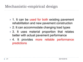

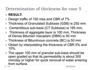
![Check for Fatigue (Continue….)
26/10/201655
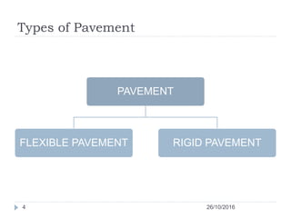
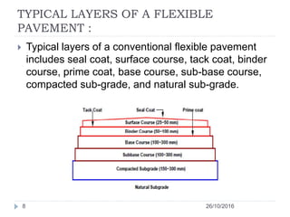
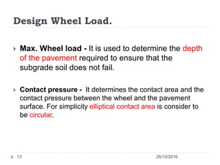
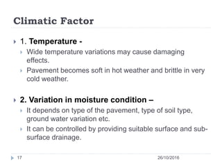
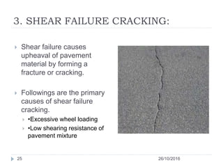
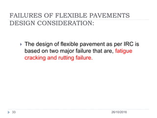
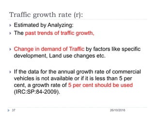
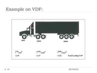
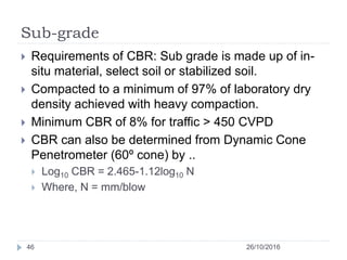
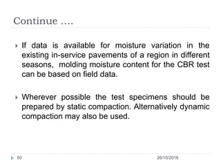
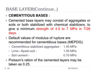
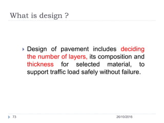
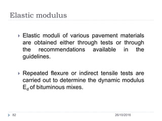
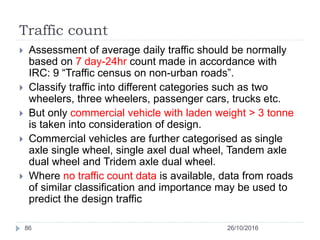
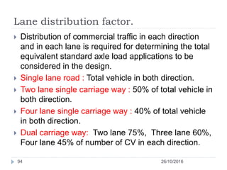
Two fatigue equations developed based on
performance data collected during various study are
Nf= 2.21 * 10-04x [1/εt]3.89* [1/MR]0.854 (80 %
reliability)…(a)
Nf= 0.711 * 10-04x [1/εt]3.89* [1/MR]0.854 (90 %
reliability)...(b)
Where,
Nf= fatigue life in number of standard axles,
εt= Maximum Tensile strain at the bottom of the
bituminous layer, and
MR= resilient modulus of the bituminous layer.
Equation for 90% reliability implies that only 10% of
the pavement area will have more than 20% cracks.](https://image.slidesharecdn.com/flexiblepavementpresentation-161120101101/85/Flexible-pavement-presentation-55-320.jpg)
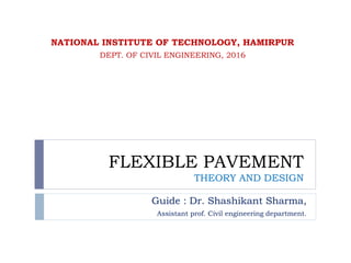
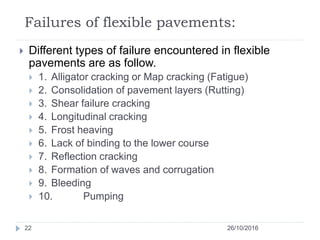
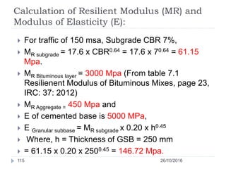
![Check for Fatigue (Continue….)
26/10/201656
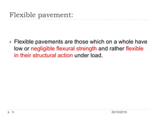
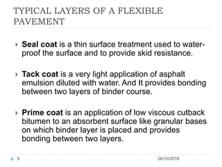
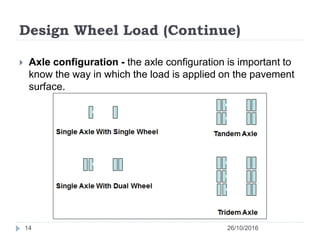
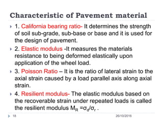
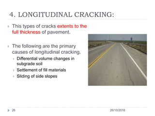
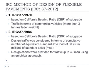
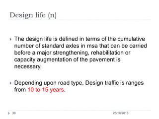
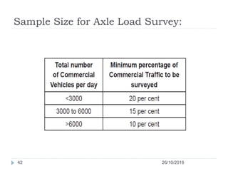
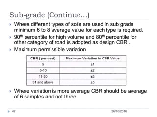
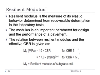
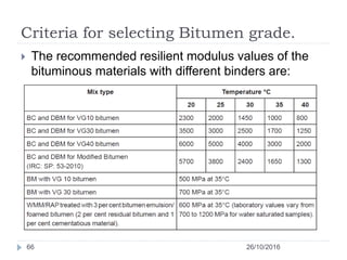
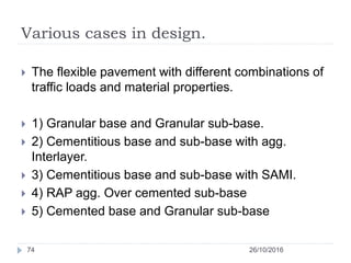
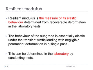
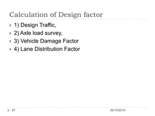
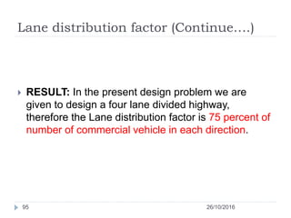
To consider the effect of volume of the bitumen and air
voids equation (b) is modified as follows
Nf =0.5161 * C * 10-04 x [1/ εt]3.89 * [1/MR]0.854………(c)
Va= per cent volume of air void and Vb= per cent volume
of bitumen in a given volume of bituminous mix.
Nf= fatigue life, єt= maximum tensile strain at the bottom
of DBM.
MR= Resilient modulus of bituminous mix.
For traffic < 30 msa consider equation (a); For traffic >
30msa equation (c) is recommened.](https://image.slidesharecdn.com/flexiblepavementpresentation-161120101101/85/Flexible-pavement-presentation-56-320.jpg)
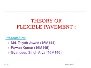
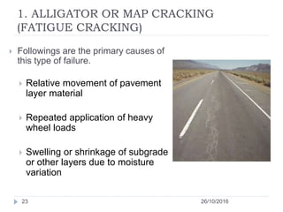
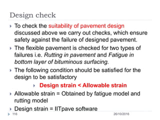
![Rutting (Continue …)
26/10/201658
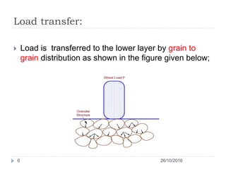
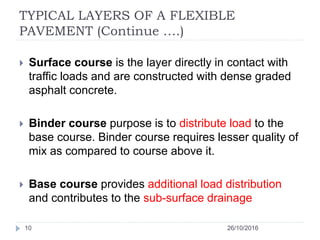
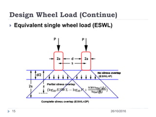
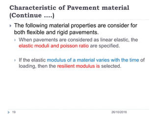
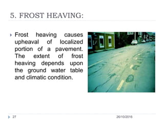
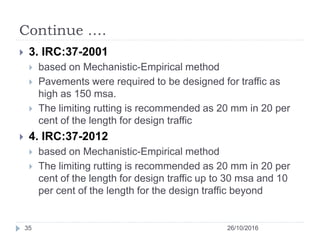
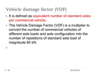
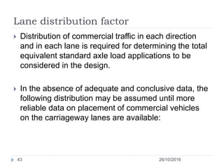
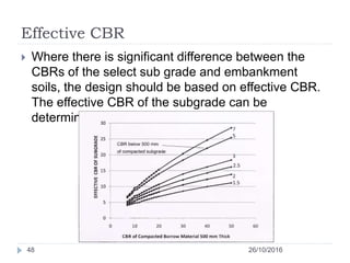
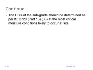
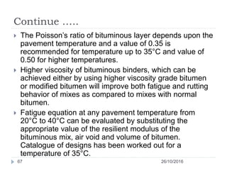
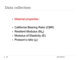
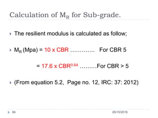
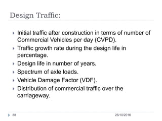
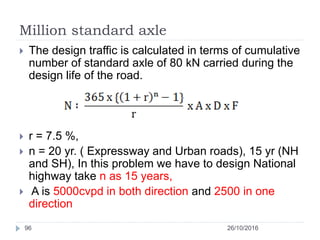
Based on various studies the two equation develops
are;
N = 4.1656 x 10-08[1/εv]4.5337 (80 per cent reliability)
N = 1.41x 10-8x [1/εv]4.5337 (90 per cent reliability)
Where,
N = Number of cumulative standard axles, and
εv= Vertical strain in the sub-grade](https://image.slidesharecdn.com/flexiblepavementpresentation-161120101101/85/Flexible-pavement-presentation-58-320.jpg)
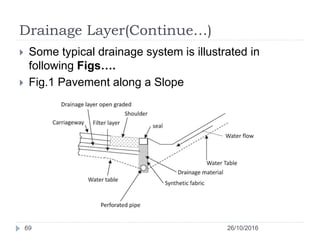

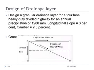
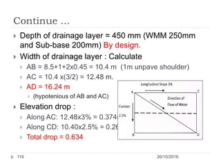
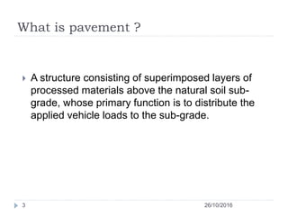
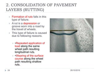
![Continue ….
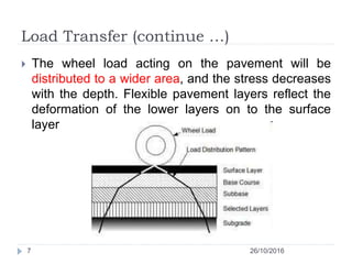
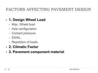
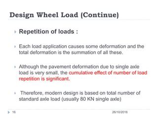
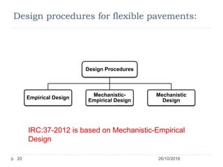
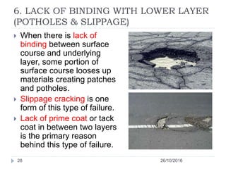
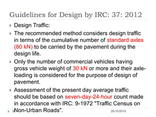
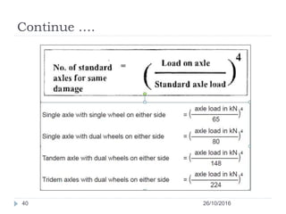
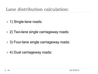
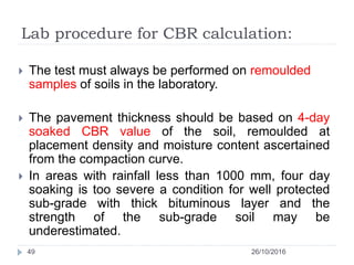
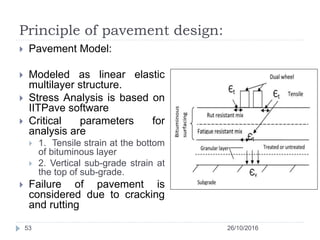
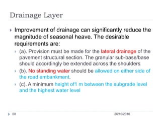
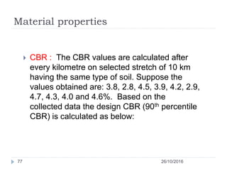
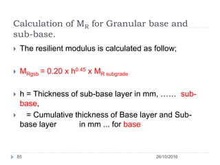
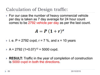
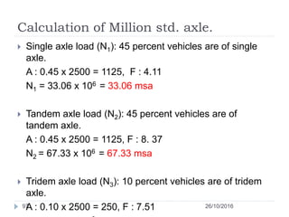
Hydraulic gradient = [Elevation drop/ length AD]
= [0.634/16.24] =0.039
Infiltration rate calculation:
qi = Ic [Nc/Wp + Wc / (Wp.Cs)]
Ic = 0.223 cub. m/day/meter
Nc = 3
Wp = 10.4 m
Wc = Wp,
Cs = 12 m
q = 0.083 Cub.meter/day/meter
26/10/2016119](https://image.slidesharecdn.com/flexiblepavementpresentation-161120101101/85/Flexible-pavement-presentation-119-320.jpg)
![References
26/10/2016126
[1] IRC: 37: 2012, “Guidelines for Design of Flexible
pavement”, second revision.
[2] IRC: 37: 2001, “Tentative guidelines for Design of
Flexible pavement”](https://image.slidesharecdn.com/flexiblepavementpresentation-161120101101/85/Flexible-pavement-presentation-126-320.jpg)


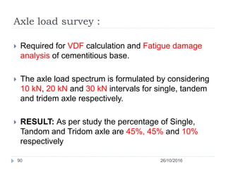
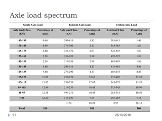
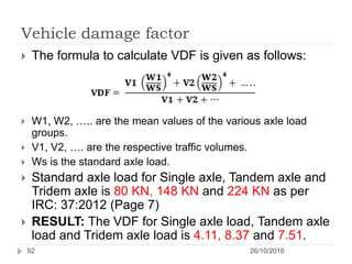
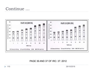
This document provides information on flexible pavement design and theory. It discusses the typical layers of a flexible pavement including the surface course, base course, and subgrade. It also outlines several factors that affect pavement design such as wheel load, climate, and material characteristics. Additionally, the document examines failures like fatigue cracking and rutting that pavement design aims to prevent. It provides guidance on mechanistic-empirical design as prescribed by the Indian Roads Congress.