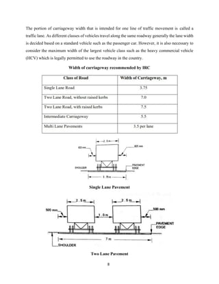
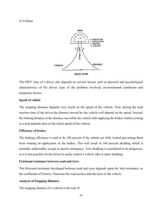
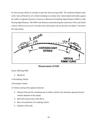
1
Module -2
HIGHWAY GEOMETRIC DESIGN
INTRODUCTION
The geometric design of highways deals with the dimensions and layout of visible features of the
highway such as horizontal and vertical alignments, sight distances and intersections. The designer
may be exposed to either plan a new highway network or improve existing highway to meet the
requirements of existing and the anticipated traffic.
It is possible to design and construct highway in stages but the geometric elements have to be
planned in the initial stages only it will be expensive and difficult to improve it later.
Geometric design of highways deals with following elements
a) Cross-Section Elements
b) Sight Distance Consideration,
c) Horizontal Alignment Details
d) Vertical Alignment Details
e) Intersection Elements
Design Controls and Criteria
Factors affecting the geometric designs are as follows
Design Controls and Criteria
The geometric design of highways depends on several design factors. The important factors which
control the geometric elements are:
(a) Design speed
(b) Topography or terrain
(c) Traffic factors
(d) Design hourly volume and capacity
(e) Environmental and other factors
Design speed
2
The design speed is the most important factor controlling the geometric design elements of
highways. The design speed is decided taking into account the overall requirements of the
highway. In India, different speed standards have been assigned depending upon the importance
or the class of the road such as National/State Highways, Major/Other District Roads and Village
Roads. Further the design speed standards are modified depending upon the terrain or topography.
Topography
The topography or the terrain conditions influence the geometric design of highway significantly.
The terrains are classified based on the general slope of the country across the alignment, as plain,
rolling, mountainous and steep terrains. The design standards specified for different classes of
roads, are different depending on the terrain classification. Further in hilly terrain, it is necessary
to allow for steeper gradients and sharper horizontal curves due to the construction problems.
Traffic Factors
The factors associated with traffic that affect geometric design of road are the vehicular
characteristics and human characteristics of road users. It is difficult to decide the design vehicle
or standard traffic lane under mixed traffic flow.
Environmental and Other Factors
The environmental factors such as aesthetics, landscaping, air and noise pollution and other local
conditions should be given due considerations in the design of road geometrics. Some of the
arterial high-speed highways and expressways are designed for higher speed standards and
uninterrupted flow of vehicles by providing controlled access and grade separated intersections.
HIGHWAY CROSS SECTION ELEMENTS
Pavement Surface depends on the pavement type. The pavement surface type is decided based on
the availability of materials and funds, volume and composition of traffic, sub grade, and climatic
conditions. The important characteristics of the pavement are
1) Friction Considerations
2) Unevenness
3) Light Reflecting Characteristics
4) Drainage of Surface Water
3
1) Friction
The friction of skid resistance between vehicle tyre and pavement surface is one of the factors
determining the operating speed and the minimum distance requires for stopping of vehicles.
'Skid' occurs when the wheels slide without revolving or rotating or when the wheels partially
revolve i.e., when the path travelled along the road surface is more than the circumferential
movements of the wheels due to their rotation When the brakes arc applied, the wheels are locked
partially or fully, and if the vehicle moves forward, the longitudinal skidding takes place which
may van, from 0 to 100%.
While a vehicle negotiates a horizontal curve, if the centrifugal force is greater than the
counteracting forces (i.e. lateral friction and component of gravity due to super elevation) lateral
skidding takes place. The lateral skid is considered dangerous as the vehicle goes out of control
leading to an accident. The maximum lateral skid coefficient is generally equal to or slightly higher
than the forward skid coefficient in braking tests.
'Slip' occurs when a wheel revolves more than the corresponding longitudinal movement along the
roads. Slipping usually occurs in the driving wheel of a vehicle when the vehicle rapidly
accelerates from stationary position or from slow speed on pavement surface which is either
slippery and wet or when the road surface is loose with mud.
Factors Affecting Friction or Skid Resistance
The maximum friction offered by pavement surface or the skid resistance depend* upon
the following factors:
Type of pavement surface namely, cement concrete, bituminous, WBM. earth surface etc.
• Macro-texture of the pavement surface or its relative roughness.
• Condition of pavement namely.
• Type and condition of tyre.
• Speed of vehicle.
• Extent of brake application or brake efficiency.
• Load and tyre pressure.
• Temperature of tyre and pavement.
4
For the calculation purposes, the IRC has recommended the longitudinal friction co efficient values
of 0.35 to 0.40 and lateral co efficient values of 0.15. for expressways and NH’s with design speed
of 120 and 100kmph it is 0.10 and 0.11.
2) Pavement Unevenness
The longitudinal profile of the road pavement has to he even' in order to provide a good riding
comfort to fast moving vehicles and to minimise the VOC. Presence of undulations on the
pavement surface is called pavement unevenness which results in
• Increase in Discomfort and Fatigue to Road Users.
• Increase in Fuel Consumption and Tyre Wear and Increase in VOC.
• Reduction in Vehicle Operating Speed and Increase in Accident Rate.
The pavement surface should therefore be maintained w i t h minimum possible unevenness or
undulations so that the desired speed can be maintained m conformity with other geometric
standards Loose road surface increases the resistance to traction and causes increase in fuel
consumption.
The unevenness of pavement surface is commonly measured by using a simple equipment called
'Bump Integrator' (BI), in terms of Unevenness Index which is the cumulative measure of vertical
undulations of the pavement surface recorded per unit length of the road. Internationally, the riding
quality of a pavement surface is quantified in terms of 'roughness’ and is expressed as International
Roughness Index (IRI) in units of m/km. The relation between the unevenness measured using
bump integrator in mm/km and the International Roughness index in m/km is as follows
BI = 630 (IRI)1.12
Undulations of newly laid pavement surface are sometimes measured using a straight edge and
wedge scale, in terms of the depth and number of depressions or ruts along and across the
pavement. It may be mentioned here that there are several advanced techniques and equipment
available now to evaluate the pavement surface condition.
3) Light Reflecting Characteristics
5
Night visibility depends upon the color and light reflecting characteristics of the pavement surface.
The glare caused by the reflection of head lights is considerably high on wet pavement surface
than on the dry pavement.
• Light colored or white pavement surface give good visibility at night particularly during
rains: however white or light color of pavement surface may produces glare and eye strain
during bright sunlight.
• Black top pavement surface on the other hand provides very poor visibility at nights,
especially when the surface is wet.
Cross Slope or Camber
Cross slope or camber is the slope provided to the road surface in the transverse direction to drain
off the rain water from the road surface. Drainage and quick disposal of water from the pavement
surface by providing cross slope is considered important because of the following reasons:
1) To prevent the entry of surface water into the pavement layers and the subgrade soil through
pavement.
2) To prevent the entry of water into the bituminous pavement layers, as continued contact with
water causes stripping of bitumen from the aggregates and results in deterioration of the pavement
layer.
3) To remove the rain water from the pavement surface as quickly as possible and to allow the
pavement to get dry soon after the rain.
The rate of camber or cross slope is usually designated by 1 in ‘n’ which means the transverse
slope is in ratio 1 vertical to n horizontal.
The required camber of a pavement depends on
a) Type of pavement surface
b) The amount of rainfall
It is desirable not to provide excessive camber or steep cross slope on road pavements. Only the
minimum camber needed to drain off surface water may be adopted keeping in view the type of
pavement surface and the amount of rainfall in the locality. Too steep cross slope is not desirable
because of the following reasons:
6
• Transverse tilt of vehicles causes uncomfortable side thrust and a drag on the steering
wheel of automobiles. Also, the thrust on the wheels along the pavement edges is more
causing unequal wear of the tyres as well as road surface.
• Discomfort causing throw of vehicle when crossing the crown during overtaking
operations.
• Problems of possible toppling over of highly laden bullock carts and trucks.
• Formation of cross ruts due to rapid flow of water.
• Tendency of most of the vehicles to travel along the center line.
Recommended values of camber
The values of camber recommended by the IRC for different types of road surfaces are given in
the below table.
Recommended values of camber for different types of road surfaces
The cross slope for shoulders should be 0.5% steeper than the cross slope of adjoining pavement,
subject to a minimum of 3.0% and a maximum value of 5.0% for earth shoulders. The cross slope
suggested for the carriageway, paved shoulders and edge strip of expressways with bituminous
surface as well as cement concrete surface is 2.5 % in regions with annual rain fall exceeding 1000
mm and 2.0 % in places with less than 1000 mm rain fall.
SHAPE OF CROSS SLOPE
In the field, camber of the pavement cross section is provided with a suitable shape.
Different shapes that are commonly adopted are
7
1) Parabolic
2) Straight Line
3) Straights with parabolic curve
Providing Camber in the field
In order to provide the desired amount and shape of camber, templates or camber boards are
prepared with the chosen shape and specified cross slope and they can be used to check the lateral
profile of finished pavements.
a) Parabolic Camber
y = x2
/a, where, a = nW/2
b) Straight Line Camber
y = W/2n, where, W – width, n – cross slope in 1 in n
WIDTH OF PAVEMENT OR CARRIAGEWAY
The width of pavement or carriageway depends on
1) Width of Traffic Lane
2) Number of Lanes.
8
The portion of carriageway width that is intended for one line of traffic movement is called a
traffic lane. As different classes of vehicles travel along the same roadway generally the lane width
is decided based on a standard vehicle such as the passenger car. However, it is also necessary to
consider the maximum width of the largest vehicle class such as the heavy commercial vehicle
(HCV) which is legally permitted to use the roadway in the country.
Width of carriageway recommended by IRC
Single Lane Pavement
Two Lane Pavement
9
MEDIANS/TRAFFIC SEPARATORS
In highways with divided carriageway, a median is provided between two sets of traffic lanes
intended to divide the traffic moving in opposite directions. The main function of the median is to
prevent head-on collision between vehicles moving in opposite directions on adjacent lanes. The
median is also called or traffic separator. The traffic separators used may be in the form of
pavement markings, physical dividers or area separators. Pavement marking is the simplest of all
these, but this will not rule out head-on collision. The mechanical separator may be suitably
designed keeping in view safety considerations.
KERBS
Kerb indicates the boundary between the pavement and median or foot path or island or shoulder.
It is desirable to provide kerbs on urban roads. Refer Fig. There are a variety of kerb designs. Kerbs
may be mainly divided based on their functions.
a) Low or Mountable Kerbs
These types of kerbs are provided such that they encourage the traffic to remain in the through
traffic lanes and also allow the driver to enter the shoulder area with little difficulty.
b) Semi-Barrier Type Kerbs
When the pedestrian traffic is high, these kerbs are provided. Their height is 15 cm above the
pavement edge.
c) Barrier Type Kerbs
They are designed to discourage vehicles from leaving the pavement. They are provided when
there is considerable amount of pedestrian traffic. They are placed at a height of 20 cm above the
pavement edge with a steep batter.
d) Submerged Kerbs
They are used in rural roads. The kerbs are provided at pavement edges between pavement edge
and shoulder .
ROAD MARGINS
The portion of the road beyond the carriageway and on the roadway can be generally called
10
road margin. Various elements that form the road margins are given below.
Shoulders
Shoulders are provided on both sides of the pavement all along the road in the case of undivided
highway and are provided on the outer edge of the highway in divided carriage way
The important functions of shoulders are:
(a) Shoulders provide structural stability and support to the edges of the flexible pavements.
(b) The capacity of the carriageway and the operating speeds of vehicles increase if the shoulders
are laid and maintained in good condition.
(c) Shoulders serve as emergency lanes for vehicle compelled to be taken out of the main
carriageway or roadway. Shoulders should have sufficient load bearing capacity to support loaded
truck even in wet weather
(d) Shoulders also act as service lanes for vehicles that are disabled. The width of shoulder should
be adequate to accommodate stationary vehicle fairly away from the edge of adjacent lane.
Guard rails
Guard rails are provided at the edge of the shoulder when the road is constructed on a fill so that
vehicles are prevented from running off the embankment, especially when the height of the fill
exceeds 3 m. Guard stones (painted with black and white strips) are installed at suitable intervals
along the outer edge of the formation at horizontal curves of roads running on embankments along
rural areas so as to provide better night visibility of the curves under head lights of vehicles.
Footpath or side-walk
In order to provide safe facility to pedestrians to walk along the roadway, foot paths or side-walks
are provided in urban areas where the pedestrian traffic is noteworthy and the vehicular traffic is
also heavy. By providing good foot path facility, the pedestrians can keep off from the carriageway
and they are segregated from the moving vehicular traffic. Thus, the operating speeds of the
vehicular traffic increases and there will be marked reduction in accidents involving pedestrians.
Drive ways
11
Drive ways connect the highway with commercial establishment like fuel-stations, service-stations
etc. Drive ways should be properly designed and located, fairly away from an intersection. The
radius of the drive way curve should be kept as large as possible, but the width of the drive way
should be minimized to reduce the crossing distance for the pedestrians.
Cycle tracks
Cycle tracks are provided in urban areas where the volume of cycle traffic on the road is very high.
A minimum width of 2 m is provided for the cycle track and the width may be increased by 1.0 m
for each additional cycle lane.
Parking lanes
Parking lanes are provided on urban roads to allow kerb parking. As far as possible only 'parallel
parking' should be allowed as it is safer for moving vehicles. For parallel parking, the minimum
lane width should be 3.0 m.
Bus bays
Bus bays may be provided by recessing the kerb to avoid conflict with moving traffic. Bus bays
should be located at least 75 m away from the intersections.
Lay-byes
Lay-byes are provided near public conveniences with guide maps to enable drivers to stop clear
off the carriageway. Lay-byes should normally be of 3.0 width and at least 30 m length with 15 m
end tapers on both sides.
Frontage roads
Frontage roads are provided to give access to properties along an important highway with
controlled access to express way or freeway. The frontage roads may run parallel to the highway
and are isolated by a separator, with approaches to the through facility only at selected points,
preferably with grade separation.
WIDTH OF FORMATION OR ROADWAY
Width of formation or roadway is the sum of widths of pavement or carriageway including
separators, if any and the shoulders. Formation or roadway width is the top width of the highway
embankment or the bottom width of highway cutting excluding the side drains.
12
RIGHT OF WAY AND LAND WIDTH
Right of way is the area of land acquired for the road, along its alignment. The width of the acquired
land for right of way is known as 'land width' and it depends on the importance of the road and
possible future development. A minimum land width has been prescribed for each category of
road. A desirable range of land width has also been suggested for each category of road. While
acquiring land for a highway it is desirable to acquire more width of land as the cost of adjoining
land invariably increases as soon as the new highway is constructed.
SIGHT DISTANCE
Sight Distance and Importance
Sight distance is the length of road visible ahead of the driver at any instance. Sight distance
available at any location of the carriageway is the actual distance a driver with his eye level at a
specified height above the pavement surface has visibility of any stationary or moving object of
specified height which is on the carriageway ahead. The sight distance between the driver and the
object is measured along the road surface.
Restrictions to Sight Distance
Restrictions to visibility or sight distance may be caused in the following circumstances
• At horizontal curves, when the line of sight is obstructed by objects at the inner side of the
curve. Here the sight distance is measured along the centre line of the horizontal curve
when the vehicle driver is able to see another vehicle or object on the carriageway.
• At a vertical curve, the line of sight is obstructed by the road surface of the summit curve
(i.e., a vertical curve of the road with convexity upwards).
• In this case also the sight distance is measured along the centre line of the vertical curve
when the vehicle driver is able to see another vehicle or object on the road.
• At an uncontrolled intersection when a driver from one of the approach roads is able to
sight a vehicle from another approach road proceeding towards the intersection, Here the
sight distance for each vehicle driver is the distance from the position when the two can
see each other up to the intersection point of the two roads.
13
14
15
TYPES OF SIGHT DISTANCE
Sight distance required by drivers applies to geometric designs of highways and for traffic control.
Three types of sight distances are considered in the design
a) Stopping Sight Distance (SSD) or absolute minimum sight distance
b) Safe Overtaking Sight Distance (OSD) or Passing Sight Distance
c) Safe Sight Distance for entering into uncontrolled intersections.
Apart from the three situations mentioned above, the following sight distances are considered by
the IRC in highway design
d) Intermediate Sight Distance
e) Head Light Sight Distance
STOPPING SIGHT DISTANCE (SSD)
Factors on which visibility or sight distance depends
The minimum distance visible to a driver ahead or the sight distance available on a highway at any
spot should be of sufficient length to safely stop a vehicle travelling at design speed, without
collision with any other obstruction. Therefore, this Stopping Sight Distance (SSD) is also called
Absolute Minimum Sight Distance. This is also sometimes called Non- Passing Sight Distance.
The sight distance available to a driver travelling on a road at any instance depends on the
following factors:
a) Features of the road ahead
b) Height of the driver's eye above the road surface
c) Height of the object above the road surface
IRC has suggested the height of eye lev el of driver as 1.2 m and the height of the object as 0.15
m above the road surface.
Factors on which stopping distance depends
The distance within which a motor vehicle can be stopped depends upon the factors listed below
a) Total reaction time of the driver
16
b) Speed of vehicle
c) Efficiency of Brakes
d) Frictional Resistance between the road and the tyre
e) Gradient of the road, if any
TOTAL REACTION TIME OF DRIVER
Reaction time of the driver is the time taken from the instant the object is visible to the driver to
the instant the brakes are effectively applied. The actual time gap or the reaction time of the driver
depends on several factors. During this period of time the vehicle travels a certain distance at the
original speed, which may be assumed to be the design speed of the road. Thus, the stopping
distance increases with increase reaction time of the driver.
The total reaction time (t) may be split up into two parts
Perception Time
It is the time required for a driver to realise that brakes must be applied. It is the time from the
instant the object comes on the line of sight of the driver to the instant he realises that the vehicle
needs to be stopped. The perception time varies from driver to driver and also depends on several
other factors such as the distance of object and other environmental conditions.
Brake Reaction Time
It is also depending on several factors including the skill of the driver, the type of the problems
and various other environmental factors.
The total reaction time may be explained with the help of PIEV theory.
PIEV THEORY
According to PIEV theory, the total reaction time of the driver is split into four parts, viz., time
taken by the driver for
1) Perception
2) Intellection
3) Emotion
17
4) Volition
The PIEV time of a driver also depends on several factors such as physical and psychological
characteristics of the driver, type of the problem involved, environmental conditions and
temporary factors.
Speed of vehicle
The stopping distance depends very much on the speed of the vehicle. First, during the total
reaction time of the driver the distance moved by the vehicle will depend on the speed. Second,
the braking distance or the distance moved by the vehicle after applying the brakes, before coming
to a stop depends also on the initial speed of the vehicle.
Efficiency of brakes
The braking efficiency is said to be 100 percent if the wheels are fully locked preventing them
from rotating on application of the brakes. This will result in 100 percent skidding which is
normally undesirable, except in utmost emergency. Also skidding is considered to be dangerous,
as it is not possible for the driver to easily control a vehicle after it starts skidding.
Frictional resistance between road and tyres
The frictional resistance developed between road and tyres depends upon the 'skid resistance' or
the coefficient of friction, f between the road surface and the tyres of the vehicle.
Analysis of Stopping Distance
The stopping distance of a vehicle is the sum of
18
a) The distance travelled by the vehicle at uniform speed during the total reaction time, t which is
known as LAG DISTANCE.
b) The distance travelled by the vehicle after the applications of the brakes, until the vehicles comes
to a dead stop which is known as BRAKING DISTANCE.
LAG DISTANCE
During the total reaction time, t seconds the vehicle may be assumed to move forward with a
uniform speed at which the vehicle has been moving and this speed may be taken as the design
speed. If ‘v’ is the design speed in m/sec and ‘t’ is the total reaction time of the driver in seconds,
then
Lag Distance = v t
If the design speed is V kmph, then the lag distance =
= 0.278 V t ≈ 0.28 V t in meters
IRC has recommended the value of reaction time t as 2.5 sec for calculation of Stopping Distance
BRAKING DISTANCE ON LEVEL SURFACE
The coefficient of friction f depends on several factors such as the type and condition of the
pavement and the value of f decreases with the increase in speed. IRC has recommended a set of
friction co efficient values for the determination of stopping sight distance.
The braking distance,
Where l - braking distance, m
v - speed of the vehicle, m/sec
19
f - design coefficient of friction, f (0.40 to 0.35)
g – acceleration due to gravity – 9.8 m/sec2
STOPPING DISTANCE ON LEVEL ROAD
Stopping Distance, SD = Lag Distance + Braking Distance
If speed is V kmph, stopping distance
STOPPING DISTANCE AT SLOPES
If speed is V kmph, stopping distance
IRC has recommended the SSD values for different speed as follows
OVERTAKING SIGHT DISTANCE (OSD)
Over Taking Requirement
If all the vehicles travel along a road at the design speed, then theoretically there should be no need
for any overtaking. In fact, all vehicles do not move at the design speed as each driver is free to
travel at lower speeds and this is particularly true under Mixed Traffic conditions. It is necessary
20
for fast moving vehicle to overtake or pass the slow-moving traffic. The minimum distance open
to the vision of the driver of a vehicle intending to overtake slow vehicle ahead with safety against
the traffic of opposite direction is known as Minimum Overtaking Sight Distance (OSD) or Safe
Passing Sight Distance. The OSD is the distance measured along the centre line of the road which
a driver with his eye level at 1.2m above the road surface can see the top of an object 1.2m above
the road surface.
Factor Affecting OSD
• Speeds of
1) Overtaking Vehicle
2) Overtaken Vehicle
3) Vehicle coming from opposite direction
• Distance between the overtaking and overtaken vehicles, the minimum spacing between
vehicles depends on the speeds
• Skill and reaction time of the driver
• Rate of acceleration of overtaking vehicle
• Gradient of the road
21
ANALYSIS OF OSD ON A 2 – WAY ROAD
Simple overtaking process on a 2 – lane highway with 2 – way traffic movement Vehicle A
travelling at the design speed v m/sec or V kmph desires to overtake another slow-moving vehicle
B moving at a speed of vb m/sec or Vb kmph. The vehicle A has to accelerate, shift to the adjacent
right-side lane, complete the overtaking manoeuvre and return to the left lane, before oncoming
vehicle C approaches the overtaking stretch.
The overtaking manoeuvre may be split up into 3 operations, thus dividing OSD into 3 parts
d1, d2 and d3.
• d1 is the distance (m) travelled by the overtaking vehicle A during the reaction time, t
(secs) of the driver from position A1 to A2 before starting to overtake the slow vehicle B
• d2 is the distance travelled (m) travelled by the vehicle A during the actual overtaking
operation during T (secs) from position A2 to A3
• d3 is the distance (m) travelled by oncoming vehicle C during the actual overtaking
operation of A during T (secs) from position C1 to C2.
Thus, on a 2-lane road with 2-way traffic the OSD = d1 + d2 + d3 in meters
Assumptions made in the analysis
Assumptions made to calculate the values of d1,d2 and d3 (m) are given below:
• The overtaking vehicle A is forced to reduce its speed from the design speed v (m/sec) to
Vb (m/sec) of the slow vehicle B and move behind it, allowing a space s (m), till there is
an opportunity for safe overtaking operation.
22
• When the driver of vehicle A finds sufficient clear gap ahead, decides within a reaction
time t (sec) to accelerate and overtake the vehicle B, during which the vehicle A moves at
speed vb (m/sec) through a distance d1 from position A1 to A2.
• The vehicle A accelerates and overtakes the slow vehicle B within a distance d2 during the
overtaking time, T (sec) between the position A2 to A3
• The distance d2 is split up into three parts
a) Spacing, s (m) between A2 and B
b) Distance b (m) travelled by the slow vehicle B between B1 and B2 during the overtaking
manoeuvre of A
c) Spacing (m) between B2 and A3
• During this overtaking time T (sec), the vehicle C coming from opposite direction travels
through a distance d3 from position C1 to C2
Determination of the components of OSD
a) From position A1 to A2, the distance, d1 (m) travelled by overtaking vehicle A, at the reduced
speed vb (m/sec) during the reaction time, t (sec) = vb t (m). The IRC suggests that this reaction
time Y of the driver may be taken as 2.0 sec as an average value, as the aim of the driver is only
to find an opportunity to overtake. Therefore
d1 = 2vb
b) From position A2, the vehicle A starts accelerating, shifts to the adjoining lane, overtakes the
vehicle B, and shifts back to its original lane ahead of B in position A3 during the overtaking time,
T (sec). The straight distance between position A2 and A3 is taken as d2 (m), which is further split
into three parts, viz.,
d2 = (s + b + s)
c) The minimum distance between position A2 and B1 may be taken as the minimum spacing s
(m) between the two vehicles while moving with the speed vb (m/sec). The minimum spacing
between vehicles depends on their speed and is given by empirical formula
s = (0.7 vb + 6)
23
d) Now the time T depends on speed of overtaken vehicle B and the average acceleration a (m/sec2
)
of overtaking vehicle A. The overtaking time T (sec) may be calculated by equating the distance
d2 to (vb T + ½ a T2
) using the general formula for the distance
travelled by a uniformly accelerating body with initial speed vb m/sec and a is the
average acceleration during overtaking in m/sec2
d2 = (vb T + 2s)
e) The distance travelled by vehicle C moving at design speed v (m/sec) during the overtaking
operation of vehicle A i.e. during time T (sec) is the distance d2 (m) between positions C1 to C2.
Hence,
d3 = v T (m)
In m/sec units
OSD = (d1 + d2 + d3) = (vb t + vb T + 2s + vT)
Here
vb = initial speed of overtaking vehicle, m/s
t = reaction time of driver = 2 sec
V = speed of overtaking vehicle or design speed, kmph
s = spacing of vehicles = (0.7 vb + 6)
a= average acceleration during overtaking, m/sec2
.
In kmph units
OSD = 0.28 Vb t + 0.28 Vb T + 2s + 0.28 V T
Here
Vb = initial speed of overtaking vehicle, kmph
t = reaction time of driver = 2 sec
24
V = speed of overtaking vehicle or design speed, kmph
s = spacing of vehicles = (0.2 Vb + 6)
A = average acceleration during overtaking, m/sec2
.
In case the speed of overtaken vehicle (vb or Vb) is not given, the same may be assumed as 4.5
m/sec or 16 kmph less than the design speed of the highway. Therefore,
vb = (v - 4.5) m/sec
Vb = (V - 16) kmph
where v is the design speed in m/sec
V is the design speed in kmph.
The acceleration of the overtaking vehicle varies depending on several factors such as the make
and model of the vehicle, its condition, load and the speed; actual acceleration also depends on the
characteristics of the driver. The average rate of acceleration during overtaking manoeuvre may
be taken corresponding to the design speed.
Maximum overtaking acceleration at different speeds
25
Overtaking sight distance on two-lane highways for different speeds
CRITERIA FOR SIGHT DISTANCE REQUIREMENT ON HIGHWAY
Absolute Minimum Sight Distance
SSD for the design speed is the absolute mining sight distance and this should be made available
all along the road stretch irrespective of the category of road. If on any road stretch SSD is not
available due to any reason such as obstruction to vision, immediate steps should be taken to either
26
remove the obstruction to the sight line or install suitable regulatory signs to specify the speed
limit along with appropriate warning signs.
Overtaking Sight Distance
It is desirable that adequate overtaking sight distance is available on most of the road
stretches such that the vehicles travelling at the design speed can overtake slow vehicles at the
earliest opportunity.
• On road stretches with two-way traffic movement, the minimum overtaking distance
should be (d1 + d2 + d3) where overtaking is not prohibited.
• On divided highways and on roads with one way traffic regulation, the overtaking distance
need be only (d1 + d2) as no vehicle is expected from the opposite direction.
• On divided highways with four or more lanes, it is not essential to provide the usual OSD;
however, the sight distance on any highway should be more than the SSD, which is the
absolute minimum sight distance.
Overtaking Zones
It is desirable to construct highways in such a way that the length of road visible ahead at every
point is sufficient for safe overtaking. This is seldom practicable and there may be stretches where
the safe overtaking distance cannot be provided. In such zones where overtaking or passing is not
safe or is not possible, sign posts should be installed indicating No Passing or Overtaking
Prohibited before such restricted zones start. However overtaking opportunity for vehicles moving
at design speed should be given at as frequent intervals as possible. These zones which are meant
for overtaking are called Overtaking Zones. The width of carriageway and the length of overtaking
zone should sufficient for safe overtaking. Sign posts should be installed at sufficient distance m
advance to indicate the start of the overtaking zones, this distance may be equal to
• (d1 + d2) for one-way roads
• (d1 + d2 + d3) for two-way roads
The minimum length of overtaking zone = 3 (OSD)
The desirable length of overtaking zones = 5 (OSD)
INTERMEDIATE SIGHT DISTANCE
27
At stretches of the road where requires OSD cannot be provided, as far as possible intermediate
Sight Distance ISD equal to twice SSD may be provided. The measurement of the ISD may be
made assuming both the height of the eye level of the driver and the object to be 1.2 metres above
the road surface. Therefore
ISD = 2 SSD
Sight Distance at Uncontrolled Intersections
It is important that on all approaches of intersecting roads, there is a clear view across the corners
from a sufficient distance so as to avoid collision of vehicles. This is all the more important at
uncontrolled intersections. The sight line is obstructed by structures or other objects at the corners
of the intersections. The area of unobstructed sight formed by the lines of vision is called the sight
triangle.
The design of sight distance at intersections may be based on three possible conditions,
a) Enabling the approaching vehicle to change speed
b) Enabling approaching vehicle to stop
c) Enabling stopped vehicle to cross a main road
d) Enabling the approaching vehicle to change speed
DESIGN OF HORIZONTAL ALIGNMENT
28
General
Often changes in the direction are necessitated in highway alignment due to various reasons such
as topographic considerations, obligatory points. The geometric design elements pertaining to
horizontal alignment of highway should consider safe and comfortable movement of vehicles at
the designated design speed of the highway. It is therefore necessary to avoid sudden changes in
direction with sharp curves or reverse curves which could not be safely and conveniently
negotiated by the vehicles at design speed. Improper design of horizontal alignment of roads would
necessitate speed changes resulting m higher accident rate and increase in vehicle operation cost.
Various design elements to be considered in the horizontal alignment are design speed radius of
circular curve, type and length of transition curves, super elevation, widening of pavement on
curves and required set-back distance for fulfilling sight distance requirements.
Design Speed
The design speed is the main factor on which geometric design elements depends. In other words,
the geometric details of a highway mainly depend on the design speed. All the important geometric
elements such as sight distances, radius of horizontal curve, length of horizontal transition curve,
rate of super elevation, extra widening of pavement at horizontal curve, length of summit and
valley curves are dependent on the design speed.
The design speed of roads depends upon
1) Class of the Road
2) Terrain
The speed standards of a particular class of road thus depends on the classification of terrain
through which it passes. The terrains have been classified as plain, mountainous and steep,
depending on the cross slope of the country as given in table below
29
Two values of design speeds are considered at the design stage of highway geometries namely,
1) Ruling design speed
2) Minimum design speed
As a general rule, attempt should be made to design all the geometric element of the highway for
the 'ruling design speed'. This is because ruling design speeds are guiding criteria for the geometric
design. However, 'minimum design speed’ may be accepted where site conditions or economic
considerations warrant.
The ruling design speeds suggested for the National and State Highways in India passing through
plain terrain is 100 kmph and through rolling terrain is 80kmph and minimum design speed values
standardized by the IRC for of roads on different terrains in rural (non-urban) areas are given in
Table below
30
The recommended design speeds for different classes of urban roads
1) Arterial Roads: 80 Kmph
2) Sub-Arterial Roads: 60 Kmph
3) Collector Streets: 50 Kmph
4) Local Streets: 30 Kmph
Horizontal Curves
A horizontal highway curve is a curve in plan to provide change in direction to the centre line of
a road. A simple circular curve may be designated by either the radius, R of the curve in meters or
the degree, D of the curve. The degree of the curve (D°) is the central angle subtended by an arc
of length 30 m and is given by the relation, RD𝜋/180 = 30. Therefore, the relation between the
radius and degree of the circular curve is given by, R = 1720 / D.
When a vehicle traverses a horizontal curve, the centrifugal force acts horizontally outwards
through the centre of gravity of the vehicle. The centrifugal force developed depends on the radius
of the horizontal curve and the speed of the vehicle negotiating the curve. This centrifugal force is
counteracted by the transverse frictional resistance developed between the tyres and the pavement
which enables the vehicle to change the direction along the curve and to maintain the stability of
the vehicle. Centrifugal force P is given by the equation:
Where
P = centrifugal force, kg
W = weight of the vehicle, kg
R = radius of the circular curve, m
v = speed of vehicle, m/sec
g = acceleration due to gravity = 9.8 m/sec
31
The ratio of the centrifugal force to the weight of the vehicle, P/W is known as the 'centrifugal
ratio' or the 'impact factor'. Therefore, centrifugal ratio
The centrifugal force acting on a vehicle negotiating a horizontal curve has the following two
effects:
1) Tendency to overturn the vehicle outwards about the outer wheels
2) Tendency to skid the vehicle laterally, outwards
Overturning Effect
The overturning moment due to centrifugal force, P = P x h
This is resisted by the restoring moment due to weight of the vehicle W and is equal to (Wb/2).
The equilibrium condition for overturning will occur when
And for safety
Transverse Skidding Effect
The centrifugal force developed has the tendency to push the vehicle outwards in the transverse
direction.
The equilibrium condition for the transverse skid resistance developed is given by
F = FA + FB
= f (RA + RB)
= f W
32
Where f = coefficient of friction between the tyre and the pavement surface in the transverse
direction
RA, RB = Normal Reactions at the wheels A and B
W = weight of the vehicle
Skidding takes placewhen the centrifugal ratio
For safety
SUPERELEVATION
In order to counteract the effect of centrifugal force and to reduce the tendency of thevehicle to
overturn or skid, the outer edge of the pavement is raised with respect to the inneredge, thus
providing a transverse slope throughout the length of the horizontal curve. Thistransverse
inclination to the pavement surface is known as SUPER ELEVATION or CANTor BANKING.
The rate of super elevation, 'e' is expressed as the ratio of the height of outer edge with respect to
the horizontal width.
E – Relative elevation of the outer edge
B – Width of the pavement
The general equation for design of super elevation is given by
33
e = rate of super elevation = tan θ
f = design value of lateral friction coefficient = 0.15
v = speed of the vehicle, m/sec
R = radius of the horizontal curve, m
g = acceleration due to gravity = 9.8 m/sec2
If the speed of the vehicle is given in kmph then the equation is
The maximum value of super elevation is limited to 7% or 0.07 and the minimum value of lateral
friction of coefficient f for highway is 0.15
In some situations, particularly at, some intersections it is not possible to provide super elevation
and in such cases the friction counteracts the centrifugal force fully. The allowable speed of vehicle
negotiating a turn should be restricted to the condition
The super elevation depends upon
1) Radius of the curve R,
2) Speed of the vehicle V
3) The coefficient of lateral friction f
Steps for Super Elevation Design
The steps for the design of super elevation in India from practical considerations (as per the IRC
Guidelines) are given below:
34
1) The super elevation is calculated for 75% of design speed (0.75 v m/sec or 0.75 V kmph),
neglecting the friction
2) If the calculated value of 'e' is less than 7% or 0.07 the value so obtained provided. If the value
of 'e' as per the above equation exceeds 0.07 then provide the maximum super elevation equal to
0.07 and proceed with steps 3 or 4
3) Check the coefficient of friction developed for the maximum value e = 0.07 at the full value of
design speed, v m/sec or V kmph
If the value of f thus calculated is less than 0.15, the super elevation of 0.07 is safe for the design
speed and this is accepted as the design super elevation. If not, either the radius of the horizontal
curve has to be increased or the speed has to be restricted to the safe value which will be less than
the design speed. The restricted speed or the allowable speed is calculated as given in step 4
4) The allowable speed or restricted speed (va m/sec or Va kmph) is calculated by considering the.
design coefficient of lateral friction and the maximum super elevation. The safe allowable speed
If the allowable speed, as calculated above is higher than the design speed design, then the design
is adequate and provide a super elevation of 'e' equal to 0.07. If the allowable speed is less than the
design speed, the speed is limited to the allowable Va kmph calculated above.
35
If the allowable speed Va is less than the design speed V, appropriate warning signs and speed
limit signs are to be installed.
Attainment of Super elevation in the field
Introduction of super elevation on a horizontal curve in the field is an important feature in
construction. The road cross section at the straight portion is cambered with the crown at the center
of the pavement and sloping down towards both the edges. But the cross section on the portion of
circular curve of the road is super elevated with a uniform tilt sloping down from the outer edge
of the pavement up to inner edge.
Thus, the crowned camber sections at the straight before the start of the transition curve should be
changed to a single cross slope equal to the desired superelevation at the beginning of the circular
curve. This change may be conveniently attained at a gradual and uniform rate through the length
of horizontal transition curve. The full superelevation is attained by the end of transition curve or
at the beginning of the circular curve.
The attainment of superelevation may be split up into two parts:
(a) Elimination of crown of the cambered section
(b) Rotation of pavement to attain full superelevation
RADIUS OF HORIZONTAL CURVE
Horizontal curves of highways are generally designed for the specified ruling design speed of the
highway. However, if this is not possible due to site restrictions, the horizontal curves may be
designed considering the specified minimum design speed of the highway.
For a particular speed of vehicle, the centrifugal force is dependent on the radius of the horizontal
curve. To keep the centrifugal ratio P/W or v2
/g R within a low limit, the radius of the horizontal
curve should be kept correspondingly high. The centrifugal force, P developed due to a vehicle
negotiating a horizontal curve of radius, R at a speed, v m/sec or V kmph is counteracted by the
superelevation, e and lateral friction coefficient, f.
36
v and V – ruling speeds in m/sec and Kmph
V’ – minimum design speed in kmph
e - rate of superelevation, (0.07)
f – co efficient of friction 0.15
g - acceleration due to gravity 9.8 m/sec2
WIDENING OF PAVEMENT ON HORIZONTAL CURVES
Objectives
1) An automobile such as car, bus or truck has a rigid wheel base and only the front wheels can be
turned. When the vehicle takes a turn to negotiate a horizontal curve, the rear wheels do not follow
the same path as that of the front wheels. This phenomenon is called 'off tracking'. Normally at
low speeds and up to the design speed when no lateral slipping of rear wheels take place, the rear
wheels follow the inner path on the curve as compared with those of the corresponding front
wheels. This means that if inner front wheel takes a path on the inner edge of a pavement at a
horizontal curve, inner rear wheel will be off the pavement on the inner shoulder.
The off-tracking depends on
a) The length of the wheel base of the vehicle
b) The turning angle or the radius of the horizontal curve negotiated.
2) At speeds, higher than the design speeds when the superelevation and lateral friction developed
are not fully able to counteract the outwards thrust due to the centrifugal force, some transverse
skidding may occur and the rear wheels may take paths on the outside of those traced by the front
wheels on the horizontal curves. However, this occurs only at excessively high speeds
3) The path traced by the wheels of a trailer in the case of trailer units, is also likely to be on either
side of the central path of the towing vehicle, depending on the speed, rigidity of the universal
joints and pavement roughness
4) In order to take curved path with larger radius and to have greater visibility at curve, the drivers
have tendency not to follow the central path of the lane, but to use the outer side at the beginning
of a curve.
37
5) While two vehicles cross or overtake at horizontal curve there is a psychological tendency to
maintain a greater clearance between the vehicles, than on straights for increase safety. Thus, the
required extra widening of the pavement at the horizontal curves, We depends on
a) The Length of wheel based of the vehicle l,
b) Radius of the curve negotiated R
c) The psychological factor which is a function of the speed of the vehicle and the radius of the
curve.
It has been a practice therefore to provide extra width of pavement on horizontal curves when the
radius is less than about 300 m.
Analysis of Extra Widening on Horizontal Curves
The extra widening of pavement on horizontal curves is divided into two parts.
Mechanical Widening
The widening required to account for the off-tracking due to rigidity of wheel base is called as
‘Mechanical Widening’ (Wm) and is given by
Psychological Widening
Widening of pavements has to be done for some psychological reasons also. There is a tendency
for the drivers to drive close to the edges of the pavement on curves. Some extra space is to be
provided for more clearance for the crossing and overtaking operations on curves. IRC proposed
an empirical relation for the psychological widening at horizontal curves.
Hence Total Widening We is given by We = Wm + Wps
38
R – Radius of the curve
n – No of lanes
l – length of wheel base of longest vehicle, m
Note: For multi lane roads, the pavement widening is calculated by adding half extra width of
two lane roads to each lane of the multi lane road.
Horizontal Transition Curves
Transition curve is provided to change the horizontal alignment from straight to circular curve
gradually and has a radius which decreases from infinity at the straight end (tangent point) to the
desired radius of the circular curve at the other end (curve point) Thus, the functions of transition
curve in the horizontal alignment are given below:
• To introduce gradually the centrifugal force between the tangent point and the beginning
of the circular curve, avoiding sudden jerk on the vehicle. This increases the comfort of
passengers.
• To enable the driver, turn the steering gradually for his own comfort and safety
• To enable gradual introduction of the designed super elevation and extra widening of
pavement at the start of the circular curve.
• To improve the aesthetic appearance of the road
Type of transition curve
Different types of transition curves are
39
a) Spiral or Clothoid
b) Cubic Parabola
c) Lemniscates
IRC recommends spiral as the transition curve because:
1) It full fills the requirement of an ideal transition, as the rate of change of centrifugal
acceleration is uniform throughout the length.
2) The geometric property of spiral is such that the calculation and setting out the curve in
the field is simple and easy.
Length of transition curve
The length of the transition curve should be determined as the maximum of the
following three criteria
1) Rate of Change of Centrifugal Acceleration
2) Rate of Change of Super Elevation
3) An Empirical Formula Given by IRC
Rate of Change of Centrifugal Acceleration
At the tangent point, radius is infinity and hence centrifugal acceleration (v/R) is zero, as the radius
is infinity. At the end of the transition, the radius R has minimum value Rm. Hence the rate of
change of centrifugal acceleration is distributed over a length Ls.
Let the length of transition curve be Ls m. If ‘t’ is the time taken in seconds to traverse this
transition length at uniform design speed of v m/sec, t = Ls/v. The maximum centrifugal
acceleration of v2
/R is introduced in time t through the transition length Ls and hence the rate of
centrifugal acceleration C is given by
40
The IRC has recommended the following equation
The minimum and maximum value of C are limited to 0.5 and 0.8 m/sec3
The length of the transition curve Ls is given by
If the design speed is given in kmph
C - rate of change of centrifugal acceleration, m/sec3
Ls – length of transition curve, m
R – radius of the circular curve, m
Rate of introduction of super-elevation
Raise (E) of the outer edge with respect to inner edge is given by
If it is assumed that the pavement is rotated about the centre line after neutralizing the camber,
then the max amount by which the outer edge is to be raised at the circular curve with respect to
the centre = E/2. Hence the rate of change of this raise from 0 to E is achieved gradually with a
gradient of 1 in N over the length of the transition curve (typical range of N is 60-150). Therefore,
the length of the transition curve Ls is given by
41
However, if the pavement is rotated about the inner edge, the length of transition curve is given by
By Empirical Formula
According to IRC standards the length of horizontal transition curve Ls should not be less than the
value given by the following formulas for two terrain classification
a) For plain and rolling terrain
b) For mountainous and steep terrain
Setting out Transition Curve
Transition curves are introduced between the tangent points of the straight stretches and the end
of the circular curve on both sides. If the length of transition curve is Ls and the radius of the
circular curve is R, the shift S of the transition curve is given by the formula
Setback Distance on Horizontal Curves
Setback distance m or the clearance distance is the distance required from the centerline of a
horizontal curve to an obstruction on the inner side of the curve to provide adequate sight distance
at a horizontal curve. The setback distance depends on:
42
a) Required Sight Distance, S
b) Radius of Horizontal Curve, R
c) Length of the curve, Lc which may be greater or lesser than S
a) When Lc > S
When the length of curve Lc is greater than the sight distance S, let the angle subtended by the arc
length S at the curve be α. On narrow roads such as single lane roads, the sight distance is measured
along the centre line of the road and the angle subtended at the centre, α is equal to S/R radians.
Therefore, half central angle id given by
The setback distance m, required from the centre line on narrow road is given by
In case of wide roads with 2 or more lanes, if d is the distance between the centre line of the road
and the centre line of the inside lane in meters, the sight distance is measured along the middle of
the inner side lanes and the setback distance m’ is given by
Where
b) When Lc < S
43
If the length of the curve Lc is less than the required sight distance S, then the angle α subtended
at the center is determined with reference to the length of circular curve Lc and the setback distance
m’ is worked out in 2 parts
The setback distance is given by
Curve Resistance
When the vehicle negotiates a horizontal curve, the direction of rotation of the front and the rear
wheels are different. The front wheels are turned to move the vehicle along the curve, whereas the
rear wheels seldom turn. The rear wheels exert a tractive force T in the PQ direction. The tractive
force available on the front wheels is T cos θ in the PS direction. This is less than the actual tractive
force, T applied. Hence, the loss of tractive force for a vehicle to negotiate a horizontal curve is:
CR = T – T cos α = T (1 – cos α)
DESIGN OF VERTICAL ALIGNMENT
INTRODUCTION
The natural ground or the topography may be level at some places, but may have slopes of varying
magnitudes at other locations. While aligning a highway it is the common practice to follow the
general topography or profile of the land, keeping in view the drainage and other requirements on
each stretch. This is particularly with a view to minimise deep cuttings and very high
embankments. Hence the vertical profile of a road would have level stretches as well as slopes or
grades.
In order to have smooth vehicle movements on the roads, the changes in the gradient should be
smoothened out by the vertical curves. The vertical alignment is the elevation or profile of the
centre line of the road. The vertical alignment consists of grades and vertical curves.
44
The vertical alignment of a highway influences
1) Vehicle Speed
2) Acceleration and Deceleration
3) Stopping Distance
4) Sight Distance
5) Comfort While Travelling at High Speeds
6) Vehicle Operation Cost.
Gradient
Gradient is the rate of rise or fall along the length of the road with respect to the horizontal. It is
expressed as a ratio of 1 in x (1 vertical unit to x horizontal units). The gradient is also expressed
as percentages such as n%, the slope being n vertical units to 100 horizontal units.
Types of gradient
a) Ruling Gradient
b) Limiting Gradient
c) Exceptional Gradient
d) Minimum Gradient
Ruling gradient
The ruling gradient or the design gradient is the maximum gradient with which the designer
attempts to design the vertical profile of the road. This depends on the terrain, length of the grade,
speed, pulling power of the vehicle and the presence of the horizontal curve. In plain terrain, it
may be possible to provide at gradients, but in hilly terrain it is not economical and sometimes not
possible also.
The IRC has recommended ruling gradient values of
a) 1 in 30 on plain and rolling terrain
b) 1 in 20 on mountainous terrain
c) 1 in 16.7 on steep terrain.
45
Limiting gradient
Where topography of a place compels adopting steeper gradient than the ruling gradient, 'limiting
gradient' is used in view of enormous increase in cost in constructing roads with gentler gradients.
However, the length of continuous grade line steeper than ruling gradient should be limited. On
rolling terrain and on hill roads, it may be frequently necessary to exceed ruling gradient and adopt
limiting gradient, but care should be taken to separate such stretches of steep gradients by
providing either a level road or a road with easier grade.
Exceptional gradient
In some extra ordinary situations, it may be unavoidable to provide still steeper gradients than
limiting gradient at least for short stretches and in such cases the steeper gradient up to 'exceptional
gradient' may be provided. However, the exceptional gradient should be strictly limited only for
short stretches not exceeding about 100 m at a stretch.
Minimum gradient
This is important only at locations where surface drainage is important. Camber will take care of
the lateral drainage. But the longitudinal drainage along the side drains requires some slope for
smooth flow of water.
The road with zero gradient passing through level land and open side drains are provided with a
gradient of 1 in 400.A minimum of 1 in 500 may be sufficient to drain water in concrete drains or
gutter, on inferior surface of drains 1 in 200 or 0.5%, on kutcha open drains steeper slope up to 1
in 100 or 1 % may be provided.
Gradient for roads in different terrains
46
Grade Compensation on Horizontal Curve
When sharp horizontal curve is to be introduced on a road which has already the maximum
permissible gradient, then the gradient should be decreased to compensate for the loss of tractive
effort due to curve. This reduction in gradient at the horizontal curve is called Grade compensation
or compensation in gradiebt at the horizontal curve, which is intended to off-set the extra tractive
effort involved at the curve. This is calculated from the below equation
Grade Compensation % = (𝟑𝟎+𝑹)/𝑹
The max value of grade compensation is limited to 75/R, where R is the radius of the circular curve
in m
As per IRC the grade compensation is not necessary for gradients flatter than 4.0 %, and therefore
when applying grade compensation correction, the gradients need not be eased beyond 4 %. The
compensated gradient = Ruling Gradient – Grade Compensation
Vertical Curves
Due to changes in grade in the vertical alignment of highway, it is necessary to introduce vertical
curve at the intersections of different grades to smoothen out the vertical profile and thus ease off
the changes in gradients for the fast moving vehicles.
The vertical curves used in highway may be classified into two categories:
(a) Summit curves or crest curves with convexity upwards
(b) Valley curves or sag curves with concavity upwards
47
Summit curves
Summit curves with convexity upwards are formed in any one of the cases as given below
a) When a positive gradient meets another positive gradient
b) When positive gradient meets a at gradient
c) When an ascending gradient meets a descending gradient.
d) When a descending gradient meets another descending gradient
The deviation angle, N between the two intersecting gradients is equal to the algebraic difference
between them. Among all the cases, the deviation angle will be maximum when an ascending
gradient, (+ n1) meets with a descending gradient, (- n2).
Therefore, deviation angle, N= n1 - (- n2) = (n1 + n2) When a fast moving vehicle travels along a
summit curve, the centrifugal force will act upwards, against gravity and hence a part of the self-
weight of the vehicle is relieved resulting in reduction in pressure on the tyres and on the
suspension springs of the vehicle suspensions.So there is no problem of discomfort to passengers
on summit curves, particularly because the deviation angles on roads are quite small. Also if the
summit curve is designed to have adequatesight distance, the length of the summit curve would be
long enough to ease the shock due to change in gradients.
48
Type of Summit Curve
Many curve forms can be used with satisfactory results; the common practice has been to use
parabolic curves in summit curves. This is primarily because of the ease with it can be laid out as
well as allowing a comfortable transition from one gradient to another.
LENGTH OF THE SUMMIT CURVE
The important design aspect of the summit curve is the determination of the length of the curve
which is parabolic. As noted earlier, the length of the curve is guided by the sight distance
consideration.
Length of the summit curve for SSD
a) When L > SSD
The equation for length L of the parabolic curve is given by
Here
L – length of summit curve, m
S – SSD, m
N – Deviation angle, equal to algebraic difference in grades, radians, or tangent of deviation
angle
H - Height of eye level of driver above road surface, m = 1.2m
h – Height of subject above the pavement surface, m = 0.15m
As per IRC
b) When L < SSD
49
The equation for length L of the parabolic curve is given by
As per IRC
The minimum radius of parabolic summit curve is given by R/N
Length of the summit curve for OSD or ISD
a) When L > OSD or ISD
The equation for length L of the parabolic curve is given by
As per IRC
S – OSD or ISD, m
b) When L < OSD or ISD
The equation for length L of the parabolic curve is given by
As per IRC
50
Valley curve
Valley curve or sag curves are vertical curves with convexity downwards. The deviation
angle, N between the two intersecting gradients is equal to the algebraic difference between
them. Among all the cases, the deviation angle will be maximum when a descending gradient,
(- n1) meets with an ascending gradient, (+ n2).
Therefore, deviation angle, N= - n1 - (+ n2) = - (n1 + n2)
They are formed when two gradients meet as illustrated in figure below in any of the
following four ways:
1) When a descending gradient meets another descending gradient
2) When a descending gradient meets a at gradient
3) When a descending gradient meets an ascendinggradient
4) When an ascending gradient meets another ascending gradient
Length of the valley curve
The length of the valley transition curve is designed to fulfil two criteria
a) Allowable rate change of centrifugal acceleration
51
b) The required HSD for night driving
Length of transition curve for Comfort condition
The equation for length L of the parabolic curve is given by
Where
L – Total length of valley curve = 2Ls
N – Deviation angle, equal to algebraic difference in grades, radians, or tangent of deviation
angle
C – the allowable rate of change of centrifugal acceleration, the value of C may be taken as
0.6m/sec3
v – Design speed in m/s
V – design speed in kmph
The minimum radius of cubic parabolic valley curve is given by
Length of the summit curve for OSD or ISD
a) When L > OSD or ISD
If the valley curve is assumed to be parabolic shape, with equation y = ax2
, where a = N/2L
The equation for length L of the parabolic curve is given by
Where
52
h1 – the average height of head light = 0.75m
α - 1º, the beam angle
L – Total length of valley curve, m
S – OSD or ISD, m
N - Deviation angle = (n1 + n2), with slopes – n1 and + n2
b) When L < OSD or ISD
The equation for length L of the parabolic curve is given by
Where
h1 – the average height of head light = 0.75m
α - 1º, the beam angle

Transportation Engineering -21CV52- Module 2

  • 1.
    1 Module -2 HIGHWAY GEOMETRICDESIGN INTRODUCTION The geometric design of highways deals with the dimensions and layout of visible features of the highway such as horizontal and vertical alignments, sight distances and intersections. The designer may be exposed to either plan a new highway network or improve existing highway to meet the requirements of existing and the anticipated traffic. It is possible to design and construct highway in stages but the geometric elements have to be planned in the initial stages only it will be expensive and difficult to improve it later. Geometric design of highways deals with following elements a) Cross-Section Elements b) Sight Distance Consideration, c) Horizontal Alignment Details d) Vertical Alignment Details e) Intersection Elements Design Controls and Criteria Factors affecting the geometric designs are as follows Design Controls and Criteria The geometric design of highways depends on several design factors. The important factors which control the geometric elements are: (a) Design speed (b) Topography or terrain (c) Traffic factors (d) Design hourly volume and capacity (e) Environmental and other factors Design speed
  • 2.
    2 The design speedis the most important factor controlling the geometric design elements of highways. The design speed is decided taking into account the overall requirements of the highway. In India, different speed standards have been assigned depending upon the importance or the class of the road such as National/State Highways, Major/Other District Roads and Village Roads. Further the design speed standards are modified depending upon the terrain or topography. Topography The topography or the terrain conditions influence the geometric design of highway significantly. The terrains are classified based on the general slope of the country across the alignment, as plain, rolling, mountainous and steep terrains. The design standards specified for different classes of roads, are different depending on the terrain classification. Further in hilly terrain, it is necessary to allow for steeper gradients and sharper horizontal curves due to the construction problems. Traffic Factors The factors associated with traffic that affect geometric design of road are the vehicular characteristics and human characteristics of road users. It is difficult to decide the design vehicle or standard traffic lane under mixed traffic flow. Environmental and Other Factors The environmental factors such as aesthetics, landscaping, air and noise pollution and other local conditions should be given due considerations in the design of road geometrics. Some of the arterial high-speed highways and expressways are designed for higher speed standards and uninterrupted flow of vehicles by providing controlled access and grade separated intersections. HIGHWAY CROSS SECTION ELEMENTS Pavement Surface depends on the pavement type. The pavement surface type is decided based on the availability of materials and funds, volume and composition of traffic, sub grade, and climatic conditions. The important characteristics of the pavement are 1) Friction Considerations 2) Unevenness 3) Light Reflecting Characteristics 4) Drainage of Surface Water
  • 3.
    3 1) Friction The frictionof skid resistance between vehicle tyre and pavement surface is one of the factors determining the operating speed and the minimum distance requires for stopping of vehicles. 'Skid' occurs when the wheels slide without revolving or rotating or when the wheels partially revolve i.e., when the path travelled along the road surface is more than the circumferential movements of the wheels due to their rotation When the brakes arc applied, the wheels are locked partially or fully, and if the vehicle moves forward, the longitudinal skidding takes place which may van, from 0 to 100%. While a vehicle negotiates a horizontal curve, if the centrifugal force is greater than the counteracting forces (i.e. lateral friction and component of gravity due to super elevation) lateral skidding takes place. The lateral skid is considered dangerous as the vehicle goes out of control leading to an accident. The maximum lateral skid coefficient is generally equal to or slightly higher than the forward skid coefficient in braking tests. 'Slip' occurs when a wheel revolves more than the corresponding longitudinal movement along the roads. Slipping usually occurs in the driving wheel of a vehicle when the vehicle rapidly accelerates from stationary position or from slow speed on pavement surface which is either slippery and wet or when the road surface is loose with mud. Factors Affecting Friction or Skid Resistance The maximum friction offered by pavement surface or the skid resistance depend* upon the following factors: Type of pavement surface namely, cement concrete, bituminous, WBM. earth surface etc. • Macro-texture of the pavement surface or its relative roughness. • Condition of pavement namely. • Type and condition of tyre. • Speed of vehicle. • Extent of brake application or brake efficiency. • Load and tyre pressure. • Temperature of tyre and pavement.
  • 4.
    4 For the calculationpurposes, the IRC has recommended the longitudinal friction co efficient values of 0.35 to 0.40 and lateral co efficient values of 0.15. for expressways and NH’s with design speed of 120 and 100kmph it is 0.10 and 0.11. 2) Pavement Unevenness The longitudinal profile of the road pavement has to he even' in order to provide a good riding comfort to fast moving vehicles and to minimise the VOC. Presence of undulations on the pavement surface is called pavement unevenness which results in • Increase in Discomfort and Fatigue to Road Users. • Increase in Fuel Consumption and Tyre Wear and Increase in VOC. • Reduction in Vehicle Operating Speed and Increase in Accident Rate. The pavement surface should therefore be maintained w i t h minimum possible unevenness or undulations so that the desired speed can be maintained m conformity with other geometric standards Loose road surface increases the resistance to traction and causes increase in fuel consumption. The unevenness of pavement surface is commonly measured by using a simple equipment called 'Bump Integrator' (BI), in terms of Unevenness Index which is the cumulative measure of vertical undulations of the pavement surface recorded per unit length of the road. Internationally, the riding quality of a pavement surface is quantified in terms of 'roughness’ and is expressed as International Roughness Index (IRI) in units of m/km. The relation between the unevenness measured using bump integrator in mm/km and the International Roughness index in m/km is as follows BI = 630 (IRI)1.12 Undulations of newly laid pavement surface are sometimes measured using a straight edge and wedge scale, in terms of the depth and number of depressions or ruts along and across the pavement. It may be mentioned here that there are several advanced techniques and equipment available now to evaluate the pavement surface condition. 3) Light Reflecting Characteristics
  • 5.
    5 Night visibility dependsupon the color and light reflecting characteristics of the pavement surface. The glare caused by the reflection of head lights is considerably high on wet pavement surface than on the dry pavement. • Light colored or white pavement surface give good visibility at night particularly during rains: however white or light color of pavement surface may produces glare and eye strain during bright sunlight. • Black top pavement surface on the other hand provides very poor visibility at nights, especially when the surface is wet. Cross Slope or Camber Cross slope or camber is the slope provided to the road surface in the transverse direction to drain off the rain water from the road surface. Drainage and quick disposal of water from the pavement surface by providing cross slope is considered important because of the following reasons: 1) To prevent the entry of surface water into the pavement layers and the subgrade soil through pavement. 2) To prevent the entry of water into the bituminous pavement layers, as continued contact with water causes stripping of bitumen from the aggregates and results in deterioration of the pavement layer. 3) To remove the rain water from the pavement surface as quickly as possible and to allow the pavement to get dry soon after the rain. The rate of camber or cross slope is usually designated by 1 in ‘n’ which means the transverse slope is in ratio 1 vertical to n horizontal. The required camber of a pavement depends on a) Type of pavement surface b) The amount of rainfall It is desirable not to provide excessive camber or steep cross slope on road pavements. Only the minimum camber needed to drain off surface water may be adopted keeping in view the type of pavement surface and the amount of rainfall in the locality. Too steep cross slope is not desirable because of the following reasons:
  • 6.
    6 • Transverse tiltof vehicles causes uncomfortable side thrust and a drag on the steering wheel of automobiles. Also, the thrust on the wheels along the pavement edges is more causing unequal wear of the tyres as well as road surface. • Discomfort causing throw of vehicle when crossing the crown during overtaking operations. • Problems of possible toppling over of highly laden bullock carts and trucks. • Formation of cross ruts due to rapid flow of water. • Tendency of most of the vehicles to travel along the center line. Recommended values of camber The values of camber recommended by the IRC for different types of road surfaces are given in the below table. Recommended values of camber for different types of road surfaces The cross slope for shoulders should be 0.5% steeper than the cross slope of adjoining pavement, subject to a minimum of 3.0% and a maximum value of 5.0% for earth shoulders. The cross slope suggested for the carriageway, paved shoulders and edge strip of expressways with bituminous surface as well as cement concrete surface is 2.5 % in regions with annual rain fall exceeding 1000 mm and 2.0 % in places with less than 1000 mm rain fall. SHAPE OF CROSS SLOPE In the field, camber of the pavement cross section is provided with a suitable shape. Different shapes that are commonly adopted are
  • 7.
    7 1) Parabolic 2) StraightLine 3) Straights with parabolic curve Providing Camber in the field In order to provide the desired amount and shape of camber, templates or camber boards are prepared with the chosen shape and specified cross slope and they can be used to check the lateral profile of finished pavements. a) Parabolic Camber y = x2 /a, where, a = nW/2 b) Straight Line Camber y = W/2n, where, W – width, n – cross slope in 1 in n WIDTH OF PAVEMENT OR CARRIAGEWAY The width of pavement or carriageway depends on 1) Width of Traffic Lane 2) Number of Lanes.
  • 8.
    8 The portion ofcarriageway width that is intended for one line of traffic movement is called a traffic lane. As different classes of vehicles travel along the same roadway generally the lane width is decided based on a standard vehicle such as the passenger car. However, it is also necessary to consider the maximum width of the largest vehicle class such as the heavy commercial vehicle (HCV) which is legally permitted to use the roadway in the country. Width of carriageway recommended by IRC Single Lane Pavement Two Lane Pavement
  • 9.
    9 MEDIANS/TRAFFIC SEPARATORS In highwayswith divided carriageway, a median is provided between two sets of traffic lanes intended to divide the traffic moving in opposite directions. The main function of the median is to prevent head-on collision between vehicles moving in opposite directions on adjacent lanes. The median is also called or traffic separator. The traffic separators used may be in the form of pavement markings, physical dividers or area separators. Pavement marking is the simplest of all these, but this will not rule out head-on collision. The mechanical separator may be suitably designed keeping in view safety considerations. KERBS Kerb indicates the boundary between the pavement and median or foot path or island or shoulder. It is desirable to provide kerbs on urban roads. Refer Fig. There are a variety of kerb designs. Kerbs may be mainly divided based on their functions. a) Low or Mountable Kerbs These types of kerbs are provided such that they encourage the traffic to remain in the through traffic lanes and also allow the driver to enter the shoulder area with little difficulty. b) Semi-Barrier Type Kerbs When the pedestrian traffic is high, these kerbs are provided. Their height is 15 cm above the pavement edge. c) Barrier Type Kerbs They are designed to discourage vehicles from leaving the pavement. They are provided when there is considerable amount of pedestrian traffic. They are placed at a height of 20 cm above the pavement edge with a steep batter. d) Submerged Kerbs They are used in rural roads. The kerbs are provided at pavement edges between pavement edge and shoulder . ROAD MARGINS The portion of the road beyond the carriageway and on the roadway can be generally called
  • 10.
    10 road margin. Variouselements that form the road margins are given below. Shoulders Shoulders are provided on both sides of the pavement all along the road in the case of undivided highway and are provided on the outer edge of the highway in divided carriage way The important functions of shoulders are: (a) Shoulders provide structural stability and support to the edges of the flexible pavements. (b) The capacity of the carriageway and the operating speeds of vehicles increase if the shoulders are laid and maintained in good condition. (c) Shoulders serve as emergency lanes for vehicle compelled to be taken out of the main carriageway or roadway. Shoulders should have sufficient load bearing capacity to support loaded truck even in wet weather (d) Shoulders also act as service lanes for vehicles that are disabled. The width of shoulder should be adequate to accommodate stationary vehicle fairly away from the edge of adjacent lane. Guard rails Guard rails are provided at the edge of the shoulder when the road is constructed on a fill so that vehicles are prevented from running off the embankment, especially when the height of the fill exceeds 3 m. Guard stones (painted with black and white strips) are installed at suitable intervals along the outer edge of the formation at horizontal curves of roads running on embankments along rural areas so as to provide better night visibility of the curves under head lights of vehicles. Footpath or side-walk In order to provide safe facility to pedestrians to walk along the roadway, foot paths or side-walks are provided in urban areas where the pedestrian traffic is noteworthy and the vehicular traffic is also heavy. By providing good foot path facility, the pedestrians can keep off from the carriageway and they are segregated from the moving vehicular traffic. Thus, the operating speeds of the vehicular traffic increases and there will be marked reduction in accidents involving pedestrians. Drive ways
  • 11.
    11 Drive ways connectthe highway with commercial establishment like fuel-stations, service-stations etc. Drive ways should be properly designed and located, fairly away from an intersection. The radius of the drive way curve should be kept as large as possible, but the width of the drive way should be minimized to reduce the crossing distance for the pedestrians. Cycle tracks Cycle tracks are provided in urban areas where the volume of cycle traffic on the road is very high. A minimum width of 2 m is provided for the cycle track and the width may be increased by 1.0 m for each additional cycle lane. Parking lanes Parking lanes are provided on urban roads to allow kerb parking. As far as possible only 'parallel parking' should be allowed as it is safer for moving vehicles. For parallel parking, the minimum lane width should be 3.0 m. Bus bays Bus bays may be provided by recessing the kerb to avoid conflict with moving traffic. Bus bays should be located at least 75 m away from the intersections. Lay-byes Lay-byes are provided near public conveniences with guide maps to enable drivers to stop clear off the carriageway. Lay-byes should normally be of 3.0 width and at least 30 m length with 15 m end tapers on both sides. Frontage roads Frontage roads are provided to give access to properties along an important highway with controlled access to express way or freeway. The frontage roads may run parallel to the highway and are isolated by a separator, with approaches to the through facility only at selected points, preferably with grade separation. WIDTH OF FORMATION OR ROADWAY Width of formation or roadway is the sum of widths of pavement or carriageway including separators, if any and the shoulders. Formation or roadway width is the top width of the highway embankment or the bottom width of highway cutting excluding the side drains.
  • 12.
    12 RIGHT OF WAYAND LAND WIDTH Right of way is the area of land acquired for the road, along its alignment. The width of the acquired land for right of way is known as 'land width' and it depends on the importance of the road and possible future development. A minimum land width has been prescribed for each category of road. A desirable range of land width has also been suggested for each category of road. While acquiring land for a highway it is desirable to acquire more width of land as the cost of adjoining land invariably increases as soon as the new highway is constructed. SIGHT DISTANCE Sight Distance and Importance Sight distance is the length of road visible ahead of the driver at any instance. Sight distance available at any location of the carriageway is the actual distance a driver with his eye level at a specified height above the pavement surface has visibility of any stationary or moving object of specified height which is on the carriageway ahead. The sight distance between the driver and the object is measured along the road surface. Restrictions to Sight Distance Restrictions to visibility or sight distance may be caused in the following circumstances • At horizontal curves, when the line of sight is obstructed by objects at the inner side of the curve. Here the sight distance is measured along the centre line of the horizontal curve when the vehicle driver is able to see another vehicle or object on the carriageway. • At a vertical curve, the line of sight is obstructed by the road surface of the summit curve (i.e., a vertical curve of the road with convexity upwards). • In this case also the sight distance is measured along the centre line of the vertical curve when the vehicle driver is able to see another vehicle or object on the road. • At an uncontrolled intersection when a driver from one of the approach roads is able to sight a vehicle from another approach road proceeding towards the intersection, Here the sight distance for each vehicle driver is the distance from the position when the two can see each other up to the intersection point of the two roads.
  • 13.
  • 14.
  • 15.
    15 TYPES OF SIGHTDISTANCE Sight distance required by drivers applies to geometric designs of highways and for traffic control. Three types of sight distances are considered in the design a) Stopping Sight Distance (SSD) or absolute minimum sight distance b) Safe Overtaking Sight Distance (OSD) or Passing Sight Distance c) Safe Sight Distance for entering into uncontrolled intersections. Apart from the three situations mentioned above, the following sight distances are considered by the IRC in highway design d) Intermediate Sight Distance e) Head Light Sight Distance STOPPING SIGHT DISTANCE (SSD) Factors on which visibility or sight distance depends The minimum distance visible to a driver ahead or the sight distance available on a highway at any spot should be of sufficient length to safely stop a vehicle travelling at design speed, without collision with any other obstruction. Therefore, this Stopping Sight Distance (SSD) is also called Absolute Minimum Sight Distance. This is also sometimes called Non- Passing Sight Distance. The sight distance available to a driver travelling on a road at any instance depends on the following factors: a) Features of the road ahead b) Height of the driver's eye above the road surface c) Height of the object above the road surface IRC has suggested the height of eye lev el of driver as 1.2 m and the height of the object as 0.15 m above the road surface. Factors on which stopping distance depends The distance within which a motor vehicle can be stopped depends upon the factors listed below a) Total reaction time of the driver
  • 16.
    16 b) Speed ofvehicle c) Efficiency of Brakes d) Frictional Resistance between the road and the tyre e) Gradient of the road, if any TOTAL REACTION TIME OF DRIVER Reaction time of the driver is the time taken from the instant the object is visible to the driver to the instant the brakes are effectively applied. The actual time gap or the reaction time of the driver depends on several factors. During this period of time the vehicle travels a certain distance at the original speed, which may be assumed to be the design speed of the road. Thus, the stopping distance increases with increase reaction time of the driver. The total reaction time (t) may be split up into two parts Perception Time It is the time required for a driver to realise that brakes must be applied. It is the time from the instant the object comes on the line of sight of the driver to the instant he realises that the vehicle needs to be stopped. The perception time varies from driver to driver and also depends on several other factors such as the distance of object and other environmental conditions. Brake Reaction Time It is also depending on several factors including the skill of the driver, the type of the problems and various other environmental factors. The total reaction time may be explained with the help of PIEV theory. PIEV THEORY According to PIEV theory, the total reaction time of the driver is split into four parts, viz., time taken by the driver for 1) Perception 2) Intellection 3) Emotion
  • 17.
    17 4) Volition The PIEVtime of a driver also depends on several factors such as physical and psychological characteristics of the driver, type of the problem involved, environmental conditions and temporary factors. Speed of vehicle The stopping distance depends very much on the speed of the vehicle. First, during the total reaction time of the driver the distance moved by the vehicle will depend on the speed. Second, the braking distance or the distance moved by the vehicle after applying the brakes, before coming to a stop depends also on the initial speed of the vehicle. Efficiency of brakes The braking efficiency is said to be 100 percent if the wheels are fully locked preventing them from rotating on application of the brakes. This will result in 100 percent skidding which is normally undesirable, except in utmost emergency. Also skidding is considered to be dangerous, as it is not possible for the driver to easily control a vehicle after it starts skidding. Frictional resistance between road and tyres The frictional resistance developed between road and tyres depends upon the 'skid resistance' or the coefficient of friction, f between the road surface and the tyres of the vehicle. Analysis of Stopping Distance The stopping distance of a vehicle is the sum of
  • 18.
    18 a) The distancetravelled by the vehicle at uniform speed during the total reaction time, t which is known as LAG DISTANCE. b) The distance travelled by the vehicle after the applications of the brakes, until the vehicles comes to a dead stop which is known as BRAKING DISTANCE. LAG DISTANCE During the total reaction time, t seconds the vehicle may be assumed to move forward with a uniform speed at which the vehicle has been moving and this speed may be taken as the design speed. If ‘v’ is the design speed in m/sec and ‘t’ is the total reaction time of the driver in seconds, then Lag Distance = v t If the design speed is V kmph, then the lag distance = = 0.278 V t ≈ 0.28 V t in meters IRC has recommended the value of reaction time t as 2.5 sec for calculation of Stopping Distance BRAKING DISTANCE ON LEVEL SURFACE The coefficient of friction f depends on several factors such as the type and condition of the pavement and the value of f decreases with the increase in speed. IRC has recommended a set of friction co efficient values for the determination of stopping sight distance. The braking distance, Where l - braking distance, m v - speed of the vehicle, m/sec
  • 19.
    19 f - designcoefficient of friction, f (0.40 to 0.35) g – acceleration due to gravity – 9.8 m/sec2 STOPPING DISTANCE ON LEVEL ROAD Stopping Distance, SD = Lag Distance + Braking Distance If speed is V kmph, stopping distance STOPPING DISTANCE AT SLOPES If speed is V kmph, stopping distance IRC has recommended the SSD values for different speed as follows OVERTAKING SIGHT DISTANCE (OSD) Over Taking Requirement If all the vehicles travel along a road at the design speed, then theoretically there should be no need for any overtaking. In fact, all vehicles do not move at the design speed as each driver is free to travel at lower speeds and this is particularly true under Mixed Traffic conditions. It is necessary
  • 20.
    20 for fast movingvehicle to overtake or pass the slow-moving traffic. The minimum distance open to the vision of the driver of a vehicle intending to overtake slow vehicle ahead with safety against the traffic of opposite direction is known as Minimum Overtaking Sight Distance (OSD) or Safe Passing Sight Distance. The OSD is the distance measured along the centre line of the road which a driver with his eye level at 1.2m above the road surface can see the top of an object 1.2m above the road surface. Factor Affecting OSD • Speeds of 1) Overtaking Vehicle 2) Overtaken Vehicle 3) Vehicle coming from opposite direction • Distance between the overtaking and overtaken vehicles, the minimum spacing between vehicles depends on the speeds • Skill and reaction time of the driver • Rate of acceleration of overtaking vehicle • Gradient of the road
  • 21.
    21 ANALYSIS OF OSDON A 2 – WAY ROAD Simple overtaking process on a 2 – lane highway with 2 – way traffic movement Vehicle A travelling at the design speed v m/sec or V kmph desires to overtake another slow-moving vehicle B moving at a speed of vb m/sec or Vb kmph. The vehicle A has to accelerate, shift to the adjacent right-side lane, complete the overtaking manoeuvre and return to the left lane, before oncoming vehicle C approaches the overtaking stretch. The overtaking manoeuvre may be split up into 3 operations, thus dividing OSD into 3 parts d1, d2 and d3. • d1 is the distance (m) travelled by the overtaking vehicle A during the reaction time, t (secs) of the driver from position A1 to A2 before starting to overtake the slow vehicle B • d2 is the distance travelled (m) travelled by the vehicle A during the actual overtaking operation during T (secs) from position A2 to A3 • d3 is the distance (m) travelled by oncoming vehicle C during the actual overtaking operation of A during T (secs) from position C1 to C2. Thus, on a 2-lane road with 2-way traffic the OSD = d1 + d2 + d3 in meters Assumptions made in the analysis Assumptions made to calculate the values of d1,d2 and d3 (m) are given below: • The overtaking vehicle A is forced to reduce its speed from the design speed v (m/sec) to Vb (m/sec) of the slow vehicle B and move behind it, allowing a space s (m), till there is an opportunity for safe overtaking operation.
  • 22.
    22 • When thedriver of vehicle A finds sufficient clear gap ahead, decides within a reaction time t (sec) to accelerate and overtake the vehicle B, during which the vehicle A moves at speed vb (m/sec) through a distance d1 from position A1 to A2. • The vehicle A accelerates and overtakes the slow vehicle B within a distance d2 during the overtaking time, T (sec) between the position A2 to A3 • The distance d2 is split up into three parts a) Spacing, s (m) between A2 and B b) Distance b (m) travelled by the slow vehicle B between B1 and B2 during the overtaking manoeuvre of A c) Spacing (m) between B2 and A3 • During this overtaking time T (sec), the vehicle C coming from opposite direction travels through a distance d3 from position C1 to C2 Determination of the components of OSD a) From position A1 to A2, the distance, d1 (m) travelled by overtaking vehicle A, at the reduced speed vb (m/sec) during the reaction time, t (sec) = vb t (m). The IRC suggests that this reaction time Y of the driver may be taken as 2.0 sec as an average value, as the aim of the driver is only to find an opportunity to overtake. Therefore d1 = 2vb b) From position A2, the vehicle A starts accelerating, shifts to the adjoining lane, overtakes the vehicle B, and shifts back to its original lane ahead of B in position A3 during the overtaking time, T (sec). The straight distance between position A2 and A3 is taken as d2 (m), which is further split into three parts, viz., d2 = (s + b + s) c) The minimum distance between position A2 and B1 may be taken as the minimum spacing s (m) between the two vehicles while moving with the speed vb (m/sec). The minimum spacing between vehicles depends on their speed and is given by empirical formula s = (0.7 vb + 6)
  • 23.
    23 d) Now thetime T depends on speed of overtaken vehicle B and the average acceleration a (m/sec2 ) of overtaking vehicle A. The overtaking time T (sec) may be calculated by equating the distance d2 to (vb T + ½ a T2 ) using the general formula for the distance travelled by a uniformly accelerating body with initial speed vb m/sec and a is the average acceleration during overtaking in m/sec2 d2 = (vb T + 2s) e) The distance travelled by vehicle C moving at design speed v (m/sec) during the overtaking operation of vehicle A i.e. during time T (sec) is the distance d2 (m) between positions C1 to C2. Hence, d3 = v T (m) In m/sec units OSD = (d1 + d2 + d3) = (vb t + vb T + 2s + vT) Here vb = initial speed of overtaking vehicle, m/s t = reaction time of driver = 2 sec V = speed of overtaking vehicle or design speed, kmph s = spacing of vehicles = (0.7 vb + 6) a= average acceleration during overtaking, m/sec2 . In kmph units OSD = 0.28 Vb t + 0.28 Vb T + 2s + 0.28 V T Here Vb = initial speed of overtaking vehicle, kmph t = reaction time of driver = 2 sec
  • 24.
    24 V = speedof overtaking vehicle or design speed, kmph s = spacing of vehicles = (0.2 Vb + 6) A = average acceleration during overtaking, m/sec2 . In case the speed of overtaken vehicle (vb or Vb) is not given, the same may be assumed as 4.5 m/sec or 16 kmph less than the design speed of the highway. Therefore, vb = (v - 4.5) m/sec Vb = (V - 16) kmph where v is the design speed in m/sec V is the design speed in kmph. The acceleration of the overtaking vehicle varies depending on several factors such as the make and model of the vehicle, its condition, load and the speed; actual acceleration also depends on the characteristics of the driver. The average rate of acceleration during overtaking manoeuvre may be taken corresponding to the design speed. Maximum overtaking acceleration at different speeds
  • 25.
    25 Overtaking sight distanceon two-lane highways for different speeds CRITERIA FOR SIGHT DISTANCE REQUIREMENT ON HIGHWAY Absolute Minimum Sight Distance SSD for the design speed is the absolute mining sight distance and this should be made available all along the road stretch irrespective of the category of road. If on any road stretch SSD is not available due to any reason such as obstruction to vision, immediate steps should be taken to either
  • 26.
    26 remove the obstructionto the sight line or install suitable regulatory signs to specify the speed limit along with appropriate warning signs. Overtaking Sight Distance It is desirable that adequate overtaking sight distance is available on most of the road stretches such that the vehicles travelling at the design speed can overtake slow vehicles at the earliest opportunity. • On road stretches with two-way traffic movement, the minimum overtaking distance should be (d1 + d2 + d3) where overtaking is not prohibited. • On divided highways and on roads with one way traffic regulation, the overtaking distance need be only (d1 + d2) as no vehicle is expected from the opposite direction. • On divided highways with four or more lanes, it is not essential to provide the usual OSD; however, the sight distance on any highway should be more than the SSD, which is the absolute minimum sight distance. Overtaking Zones It is desirable to construct highways in such a way that the length of road visible ahead at every point is sufficient for safe overtaking. This is seldom practicable and there may be stretches where the safe overtaking distance cannot be provided. In such zones where overtaking or passing is not safe or is not possible, sign posts should be installed indicating No Passing or Overtaking Prohibited before such restricted zones start. However overtaking opportunity for vehicles moving at design speed should be given at as frequent intervals as possible. These zones which are meant for overtaking are called Overtaking Zones. The width of carriageway and the length of overtaking zone should sufficient for safe overtaking. Sign posts should be installed at sufficient distance m advance to indicate the start of the overtaking zones, this distance may be equal to • (d1 + d2) for one-way roads • (d1 + d2 + d3) for two-way roads The minimum length of overtaking zone = 3 (OSD) The desirable length of overtaking zones = 5 (OSD) INTERMEDIATE SIGHT DISTANCE
  • 27.
    27 At stretches ofthe road where requires OSD cannot be provided, as far as possible intermediate Sight Distance ISD equal to twice SSD may be provided. The measurement of the ISD may be made assuming both the height of the eye level of the driver and the object to be 1.2 metres above the road surface. Therefore ISD = 2 SSD Sight Distance at Uncontrolled Intersections It is important that on all approaches of intersecting roads, there is a clear view across the corners from a sufficient distance so as to avoid collision of vehicles. This is all the more important at uncontrolled intersections. The sight line is obstructed by structures or other objects at the corners of the intersections. The area of unobstructed sight formed by the lines of vision is called the sight triangle. The design of sight distance at intersections may be based on three possible conditions, a) Enabling the approaching vehicle to change speed b) Enabling approaching vehicle to stop c) Enabling stopped vehicle to cross a main road d) Enabling the approaching vehicle to change speed DESIGN OF HORIZONTAL ALIGNMENT
  • 28.
    28 General Often changes inthe direction are necessitated in highway alignment due to various reasons such as topographic considerations, obligatory points. The geometric design elements pertaining to horizontal alignment of highway should consider safe and comfortable movement of vehicles at the designated design speed of the highway. It is therefore necessary to avoid sudden changes in direction with sharp curves or reverse curves which could not be safely and conveniently negotiated by the vehicles at design speed. Improper design of horizontal alignment of roads would necessitate speed changes resulting m higher accident rate and increase in vehicle operation cost. Various design elements to be considered in the horizontal alignment are design speed radius of circular curve, type and length of transition curves, super elevation, widening of pavement on curves and required set-back distance for fulfilling sight distance requirements. Design Speed The design speed is the main factor on which geometric design elements depends. In other words, the geometric details of a highway mainly depend on the design speed. All the important geometric elements such as sight distances, radius of horizontal curve, length of horizontal transition curve, rate of super elevation, extra widening of pavement at horizontal curve, length of summit and valley curves are dependent on the design speed. The design speed of roads depends upon 1) Class of the Road 2) Terrain The speed standards of a particular class of road thus depends on the classification of terrain through which it passes. The terrains have been classified as plain, mountainous and steep, depending on the cross slope of the country as given in table below
  • 29.
    29 Two values ofdesign speeds are considered at the design stage of highway geometries namely, 1) Ruling design speed 2) Minimum design speed As a general rule, attempt should be made to design all the geometric element of the highway for the 'ruling design speed'. This is because ruling design speeds are guiding criteria for the geometric design. However, 'minimum design speed’ may be accepted where site conditions or economic considerations warrant. The ruling design speeds suggested for the National and State Highways in India passing through plain terrain is 100 kmph and through rolling terrain is 80kmph and minimum design speed values standardized by the IRC for of roads on different terrains in rural (non-urban) areas are given in Table below
  • 30.
    30 The recommended designspeeds for different classes of urban roads 1) Arterial Roads: 80 Kmph 2) Sub-Arterial Roads: 60 Kmph 3) Collector Streets: 50 Kmph 4) Local Streets: 30 Kmph Horizontal Curves A horizontal highway curve is a curve in plan to provide change in direction to the centre line of a road. A simple circular curve may be designated by either the radius, R of the curve in meters or the degree, D of the curve. The degree of the curve (D°) is the central angle subtended by an arc of length 30 m and is given by the relation, RD𝜋/180 = 30. Therefore, the relation between the radius and degree of the circular curve is given by, R = 1720 / D. When a vehicle traverses a horizontal curve, the centrifugal force acts horizontally outwards through the centre of gravity of the vehicle. The centrifugal force developed depends on the radius of the horizontal curve and the speed of the vehicle negotiating the curve. This centrifugal force is counteracted by the transverse frictional resistance developed between the tyres and the pavement which enables the vehicle to change the direction along the curve and to maintain the stability of the vehicle. Centrifugal force P is given by the equation: Where P = centrifugal force, kg W = weight of the vehicle, kg R = radius of the circular curve, m v = speed of vehicle, m/sec g = acceleration due to gravity = 9.8 m/sec
  • 31.
    31 The ratio ofthe centrifugal force to the weight of the vehicle, P/W is known as the 'centrifugal ratio' or the 'impact factor'. Therefore, centrifugal ratio The centrifugal force acting on a vehicle negotiating a horizontal curve has the following two effects: 1) Tendency to overturn the vehicle outwards about the outer wheels 2) Tendency to skid the vehicle laterally, outwards Overturning Effect The overturning moment due to centrifugal force, P = P x h This is resisted by the restoring moment due to weight of the vehicle W and is equal to (Wb/2). The equilibrium condition for overturning will occur when And for safety Transverse Skidding Effect The centrifugal force developed has the tendency to push the vehicle outwards in the transverse direction. The equilibrium condition for the transverse skid resistance developed is given by F = FA + FB = f (RA + RB) = f W
  • 32.
    32 Where f =coefficient of friction between the tyre and the pavement surface in the transverse direction RA, RB = Normal Reactions at the wheels A and B W = weight of the vehicle Skidding takes placewhen the centrifugal ratio For safety SUPERELEVATION In order to counteract the effect of centrifugal force and to reduce the tendency of thevehicle to overturn or skid, the outer edge of the pavement is raised with respect to the inneredge, thus providing a transverse slope throughout the length of the horizontal curve. Thistransverse inclination to the pavement surface is known as SUPER ELEVATION or CANTor BANKING. The rate of super elevation, 'e' is expressed as the ratio of the height of outer edge with respect to the horizontal width. E – Relative elevation of the outer edge B – Width of the pavement The general equation for design of super elevation is given by
  • 33.
    33 e = rateof super elevation = tan θ f = design value of lateral friction coefficient = 0.15 v = speed of the vehicle, m/sec R = radius of the horizontal curve, m g = acceleration due to gravity = 9.8 m/sec2 If the speed of the vehicle is given in kmph then the equation is The maximum value of super elevation is limited to 7% or 0.07 and the minimum value of lateral friction of coefficient f for highway is 0.15 In some situations, particularly at, some intersections it is not possible to provide super elevation and in such cases the friction counteracts the centrifugal force fully. The allowable speed of vehicle negotiating a turn should be restricted to the condition The super elevation depends upon 1) Radius of the curve R, 2) Speed of the vehicle V 3) The coefficient of lateral friction f Steps for Super Elevation Design The steps for the design of super elevation in India from practical considerations (as per the IRC Guidelines) are given below:
  • 34.
    34 1) The superelevation is calculated for 75% of design speed (0.75 v m/sec or 0.75 V kmph), neglecting the friction 2) If the calculated value of 'e' is less than 7% or 0.07 the value so obtained provided. If the value of 'e' as per the above equation exceeds 0.07 then provide the maximum super elevation equal to 0.07 and proceed with steps 3 or 4 3) Check the coefficient of friction developed for the maximum value e = 0.07 at the full value of design speed, v m/sec or V kmph If the value of f thus calculated is less than 0.15, the super elevation of 0.07 is safe for the design speed and this is accepted as the design super elevation. If not, either the radius of the horizontal curve has to be increased or the speed has to be restricted to the safe value which will be less than the design speed. The restricted speed or the allowable speed is calculated as given in step 4 4) The allowable speed or restricted speed (va m/sec or Va kmph) is calculated by considering the. design coefficient of lateral friction and the maximum super elevation. The safe allowable speed If the allowable speed, as calculated above is higher than the design speed design, then the design is adequate and provide a super elevation of 'e' equal to 0.07. If the allowable speed is less than the design speed, the speed is limited to the allowable Va kmph calculated above.
  • 35.
    35 If the allowablespeed Va is less than the design speed V, appropriate warning signs and speed limit signs are to be installed. Attainment of Super elevation in the field Introduction of super elevation on a horizontal curve in the field is an important feature in construction. The road cross section at the straight portion is cambered with the crown at the center of the pavement and sloping down towards both the edges. But the cross section on the portion of circular curve of the road is super elevated with a uniform tilt sloping down from the outer edge of the pavement up to inner edge. Thus, the crowned camber sections at the straight before the start of the transition curve should be changed to a single cross slope equal to the desired superelevation at the beginning of the circular curve. This change may be conveniently attained at a gradual and uniform rate through the length of horizontal transition curve. The full superelevation is attained by the end of transition curve or at the beginning of the circular curve. The attainment of superelevation may be split up into two parts: (a) Elimination of crown of the cambered section (b) Rotation of pavement to attain full superelevation RADIUS OF HORIZONTAL CURVE Horizontal curves of highways are generally designed for the specified ruling design speed of the highway. However, if this is not possible due to site restrictions, the horizontal curves may be designed considering the specified minimum design speed of the highway. For a particular speed of vehicle, the centrifugal force is dependent on the radius of the horizontal curve. To keep the centrifugal ratio P/W or v2 /g R within a low limit, the radius of the horizontal curve should be kept correspondingly high. The centrifugal force, P developed due to a vehicle negotiating a horizontal curve of radius, R at a speed, v m/sec or V kmph is counteracted by the superelevation, e and lateral friction coefficient, f.
  • 36.
    36 v and V– ruling speeds in m/sec and Kmph V’ – minimum design speed in kmph e - rate of superelevation, (0.07) f – co efficient of friction 0.15 g - acceleration due to gravity 9.8 m/sec2 WIDENING OF PAVEMENT ON HORIZONTAL CURVES Objectives 1) An automobile such as car, bus or truck has a rigid wheel base and only the front wheels can be turned. When the vehicle takes a turn to negotiate a horizontal curve, the rear wheels do not follow the same path as that of the front wheels. This phenomenon is called 'off tracking'. Normally at low speeds and up to the design speed when no lateral slipping of rear wheels take place, the rear wheels follow the inner path on the curve as compared with those of the corresponding front wheels. This means that if inner front wheel takes a path on the inner edge of a pavement at a horizontal curve, inner rear wheel will be off the pavement on the inner shoulder. The off-tracking depends on a) The length of the wheel base of the vehicle b) The turning angle or the radius of the horizontal curve negotiated. 2) At speeds, higher than the design speeds when the superelevation and lateral friction developed are not fully able to counteract the outwards thrust due to the centrifugal force, some transverse skidding may occur and the rear wheels may take paths on the outside of those traced by the front wheels on the horizontal curves. However, this occurs only at excessively high speeds 3) The path traced by the wheels of a trailer in the case of trailer units, is also likely to be on either side of the central path of the towing vehicle, depending on the speed, rigidity of the universal joints and pavement roughness 4) In order to take curved path with larger radius and to have greater visibility at curve, the drivers have tendency not to follow the central path of the lane, but to use the outer side at the beginning of a curve.
  • 37.
    37 5) While twovehicles cross or overtake at horizontal curve there is a psychological tendency to maintain a greater clearance between the vehicles, than on straights for increase safety. Thus, the required extra widening of the pavement at the horizontal curves, We depends on a) The Length of wheel based of the vehicle l, b) Radius of the curve negotiated R c) The psychological factor which is a function of the speed of the vehicle and the radius of the curve. It has been a practice therefore to provide extra width of pavement on horizontal curves when the radius is less than about 300 m. Analysis of Extra Widening on Horizontal Curves The extra widening of pavement on horizontal curves is divided into two parts. Mechanical Widening The widening required to account for the off-tracking due to rigidity of wheel base is called as ‘Mechanical Widening’ (Wm) and is given by Psychological Widening Widening of pavements has to be done for some psychological reasons also. There is a tendency for the drivers to drive close to the edges of the pavement on curves. Some extra space is to be provided for more clearance for the crossing and overtaking operations on curves. IRC proposed an empirical relation for the psychological widening at horizontal curves. Hence Total Widening We is given by We = Wm + Wps
  • 38.
    38 R – Radiusof the curve n – No of lanes l – length of wheel base of longest vehicle, m Note: For multi lane roads, the pavement widening is calculated by adding half extra width of two lane roads to each lane of the multi lane road. Horizontal Transition Curves Transition curve is provided to change the horizontal alignment from straight to circular curve gradually and has a radius which decreases from infinity at the straight end (tangent point) to the desired radius of the circular curve at the other end (curve point) Thus, the functions of transition curve in the horizontal alignment are given below: • To introduce gradually the centrifugal force between the tangent point and the beginning of the circular curve, avoiding sudden jerk on the vehicle. This increases the comfort of passengers. • To enable the driver, turn the steering gradually for his own comfort and safety • To enable gradual introduction of the designed super elevation and extra widening of pavement at the start of the circular curve. • To improve the aesthetic appearance of the road Type of transition curve Different types of transition curves are
  • 39.
    39 a) Spiral orClothoid b) Cubic Parabola c) Lemniscates IRC recommends spiral as the transition curve because: 1) It full fills the requirement of an ideal transition, as the rate of change of centrifugal acceleration is uniform throughout the length. 2) The geometric property of spiral is such that the calculation and setting out the curve in the field is simple and easy. Length of transition curve The length of the transition curve should be determined as the maximum of the following three criteria 1) Rate of Change of Centrifugal Acceleration 2) Rate of Change of Super Elevation 3) An Empirical Formula Given by IRC Rate of Change of Centrifugal Acceleration At the tangent point, radius is infinity and hence centrifugal acceleration (v/R) is zero, as the radius is infinity. At the end of the transition, the radius R has minimum value Rm. Hence the rate of change of centrifugal acceleration is distributed over a length Ls. Let the length of transition curve be Ls m. If ‘t’ is the time taken in seconds to traverse this transition length at uniform design speed of v m/sec, t = Ls/v. The maximum centrifugal acceleration of v2 /R is introduced in time t through the transition length Ls and hence the rate of centrifugal acceleration C is given by
  • 40.
    40 The IRC hasrecommended the following equation The minimum and maximum value of C are limited to 0.5 and 0.8 m/sec3 The length of the transition curve Ls is given by If the design speed is given in kmph C - rate of change of centrifugal acceleration, m/sec3 Ls – length of transition curve, m R – radius of the circular curve, m Rate of introduction of super-elevation Raise (E) of the outer edge with respect to inner edge is given by If it is assumed that the pavement is rotated about the centre line after neutralizing the camber, then the max amount by which the outer edge is to be raised at the circular curve with respect to the centre = E/2. Hence the rate of change of this raise from 0 to E is achieved gradually with a gradient of 1 in N over the length of the transition curve (typical range of N is 60-150). Therefore, the length of the transition curve Ls is given by
  • 41.
    41 However, if thepavement is rotated about the inner edge, the length of transition curve is given by By Empirical Formula According to IRC standards the length of horizontal transition curve Ls should not be less than the value given by the following formulas for two terrain classification a) For plain and rolling terrain b) For mountainous and steep terrain Setting out Transition Curve Transition curves are introduced between the tangent points of the straight stretches and the end of the circular curve on both sides. If the length of transition curve is Ls and the radius of the circular curve is R, the shift S of the transition curve is given by the formula Setback Distance on Horizontal Curves Setback distance m or the clearance distance is the distance required from the centerline of a horizontal curve to an obstruction on the inner side of the curve to provide adequate sight distance at a horizontal curve. The setback distance depends on:
  • 42.
    42 a) Required SightDistance, S b) Radius of Horizontal Curve, R c) Length of the curve, Lc which may be greater or lesser than S a) When Lc > S When the length of curve Lc is greater than the sight distance S, let the angle subtended by the arc length S at the curve be α. On narrow roads such as single lane roads, the sight distance is measured along the centre line of the road and the angle subtended at the centre, α is equal to S/R radians. Therefore, half central angle id given by The setback distance m, required from the centre line on narrow road is given by In case of wide roads with 2 or more lanes, if d is the distance between the centre line of the road and the centre line of the inside lane in meters, the sight distance is measured along the middle of the inner side lanes and the setback distance m’ is given by Where b) When Lc < S
  • 43.
    43 If the lengthof the curve Lc is less than the required sight distance S, then the angle α subtended at the center is determined with reference to the length of circular curve Lc and the setback distance m’ is worked out in 2 parts The setback distance is given by Curve Resistance When the vehicle negotiates a horizontal curve, the direction of rotation of the front and the rear wheels are different. The front wheels are turned to move the vehicle along the curve, whereas the rear wheels seldom turn. The rear wheels exert a tractive force T in the PQ direction. The tractive force available on the front wheels is T cos θ in the PS direction. This is less than the actual tractive force, T applied. Hence, the loss of tractive force for a vehicle to negotiate a horizontal curve is: CR = T – T cos α = T (1 – cos α) DESIGN OF VERTICAL ALIGNMENT INTRODUCTION The natural ground or the topography may be level at some places, but may have slopes of varying magnitudes at other locations. While aligning a highway it is the common practice to follow the general topography or profile of the land, keeping in view the drainage and other requirements on each stretch. This is particularly with a view to minimise deep cuttings and very high embankments. Hence the vertical profile of a road would have level stretches as well as slopes or grades. In order to have smooth vehicle movements on the roads, the changes in the gradient should be smoothened out by the vertical curves. The vertical alignment is the elevation or profile of the centre line of the road. The vertical alignment consists of grades and vertical curves.
  • 44.
    44 The vertical alignmentof a highway influences 1) Vehicle Speed 2) Acceleration and Deceleration 3) Stopping Distance 4) Sight Distance 5) Comfort While Travelling at High Speeds 6) Vehicle Operation Cost. Gradient Gradient is the rate of rise or fall along the length of the road with respect to the horizontal. It is expressed as a ratio of 1 in x (1 vertical unit to x horizontal units). The gradient is also expressed as percentages such as n%, the slope being n vertical units to 100 horizontal units. Types of gradient a) Ruling Gradient b) Limiting Gradient c) Exceptional Gradient d) Minimum Gradient Ruling gradient The ruling gradient or the design gradient is the maximum gradient with which the designer attempts to design the vertical profile of the road. This depends on the terrain, length of the grade, speed, pulling power of the vehicle and the presence of the horizontal curve. In plain terrain, it may be possible to provide at gradients, but in hilly terrain it is not economical and sometimes not possible also. The IRC has recommended ruling gradient values of a) 1 in 30 on plain and rolling terrain b) 1 in 20 on mountainous terrain c) 1 in 16.7 on steep terrain.
  • 45.
    45 Limiting gradient Where topographyof a place compels adopting steeper gradient than the ruling gradient, 'limiting gradient' is used in view of enormous increase in cost in constructing roads with gentler gradients. However, the length of continuous grade line steeper than ruling gradient should be limited. On rolling terrain and on hill roads, it may be frequently necessary to exceed ruling gradient and adopt limiting gradient, but care should be taken to separate such stretches of steep gradients by providing either a level road or a road with easier grade. Exceptional gradient In some extra ordinary situations, it may be unavoidable to provide still steeper gradients than limiting gradient at least for short stretches and in such cases the steeper gradient up to 'exceptional gradient' may be provided. However, the exceptional gradient should be strictly limited only for short stretches not exceeding about 100 m at a stretch. Minimum gradient This is important only at locations where surface drainage is important. Camber will take care of the lateral drainage. But the longitudinal drainage along the side drains requires some slope for smooth flow of water. The road with zero gradient passing through level land and open side drains are provided with a gradient of 1 in 400.A minimum of 1 in 500 may be sufficient to drain water in concrete drains or gutter, on inferior surface of drains 1 in 200 or 0.5%, on kutcha open drains steeper slope up to 1 in 100 or 1 % may be provided. Gradient for roads in different terrains
  • 46.
    46 Grade Compensation onHorizontal Curve When sharp horizontal curve is to be introduced on a road which has already the maximum permissible gradient, then the gradient should be decreased to compensate for the loss of tractive effort due to curve. This reduction in gradient at the horizontal curve is called Grade compensation or compensation in gradiebt at the horizontal curve, which is intended to off-set the extra tractive effort involved at the curve. This is calculated from the below equation Grade Compensation % = (𝟑𝟎+𝑹)/𝑹 The max value of grade compensation is limited to 75/R, where R is the radius of the circular curve in m As per IRC the grade compensation is not necessary for gradients flatter than 4.0 %, and therefore when applying grade compensation correction, the gradients need not be eased beyond 4 %. The compensated gradient = Ruling Gradient – Grade Compensation Vertical Curves Due to changes in grade in the vertical alignment of highway, it is necessary to introduce vertical curve at the intersections of different grades to smoothen out the vertical profile and thus ease off the changes in gradients for the fast moving vehicles. The vertical curves used in highway may be classified into two categories: (a) Summit curves or crest curves with convexity upwards (b) Valley curves or sag curves with concavity upwards
  • 47.
    47 Summit curves Summit curveswith convexity upwards are formed in any one of the cases as given below a) When a positive gradient meets another positive gradient b) When positive gradient meets a at gradient c) When an ascending gradient meets a descending gradient. d) When a descending gradient meets another descending gradient The deviation angle, N between the two intersecting gradients is equal to the algebraic difference between them. Among all the cases, the deviation angle will be maximum when an ascending gradient, (+ n1) meets with a descending gradient, (- n2). Therefore, deviation angle, N= n1 - (- n2) = (n1 + n2) When a fast moving vehicle travels along a summit curve, the centrifugal force will act upwards, against gravity and hence a part of the self- weight of the vehicle is relieved resulting in reduction in pressure on the tyres and on the suspension springs of the vehicle suspensions.So there is no problem of discomfort to passengers on summit curves, particularly because the deviation angles on roads are quite small. Also if the summit curve is designed to have adequatesight distance, the length of the summit curve would be long enough to ease the shock due to change in gradients.
  • 48.
    48 Type of SummitCurve Many curve forms can be used with satisfactory results; the common practice has been to use parabolic curves in summit curves. This is primarily because of the ease with it can be laid out as well as allowing a comfortable transition from one gradient to another. LENGTH OF THE SUMMIT CURVE The important design aspect of the summit curve is the determination of the length of the curve which is parabolic. As noted earlier, the length of the curve is guided by the sight distance consideration. Length of the summit curve for SSD a) When L > SSD The equation for length L of the parabolic curve is given by Here L – length of summit curve, m S – SSD, m N – Deviation angle, equal to algebraic difference in grades, radians, or tangent of deviation angle H - Height of eye level of driver above road surface, m = 1.2m h – Height of subject above the pavement surface, m = 0.15m As per IRC b) When L < SSD
  • 49.
    49 The equation forlength L of the parabolic curve is given by As per IRC The minimum radius of parabolic summit curve is given by R/N Length of the summit curve for OSD or ISD a) When L > OSD or ISD The equation for length L of the parabolic curve is given by As per IRC S – OSD or ISD, m b) When L < OSD or ISD The equation for length L of the parabolic curve is given by As per IRC
  • 50.
    50 Valley curve Valley curveor sag curves are vertical curves with convexity downwards. The deviation angle, N between the two intersecting gradients is equal to the algebraic difference between them. Among all the cases, the deviation angle will be maximum when a descending gradient, (- n1) meets with an ascending gradient, (+ n2). Therefore, deviation angle, N= - n1 - (+ n2) = - (n1 + n2) They are formed when two gradients meet as illustrated in figure below in any of the following four ways: 1) When a descending gradient meets another descending gradient 2) When a descending gradient meets a at gradient 3) When a descending gradient meets an ascendinggradient 4) When an ascending gradient meets another ascending gradient Length of the valley curve The length of the valley transition curve is designed to fulfil two criteria a) Allowable rate change of centrifugal acceleration
  • 51.
    51 b) The requiredHSD for night driving Length of transition curve for Comfort condition The equation for length L of the parabolic curve is given by Where L – Total length of valley curve = 2Ls N – Deviation angle, equal to algebraic difference in grades, radians, or tangent of deviation angle C – the allowable rate of change of centrifugal acceleration, the value of C may be taken as 0.6m/sec3 v – Design speed in m/s V – design speed in kmph The minimum radius of cubic parabolic valley curve is given by Length of the summit curve for OSD or ISD a) When L > OSD or ISD If the valley curve is assumed to be parabolic shape, with equation y = ax2 , where a = N/2L The equation for length L of the parabolic curve is given by Where
  • 52.
    52 h1 – theaverage height of head light = 0.75m α - 1º, the beam angle L – Total length of valley curve, m S – OSD or ISD, m N - Deviation angle = (n1 + n2), with slopes – n1 and + n2 b) When L < OSD or ISD The equation for length L of the parabolic curve is given by Where h1 – the average height of head light = 0.75m α - 1º, the beam angle