Downloaded 139 times

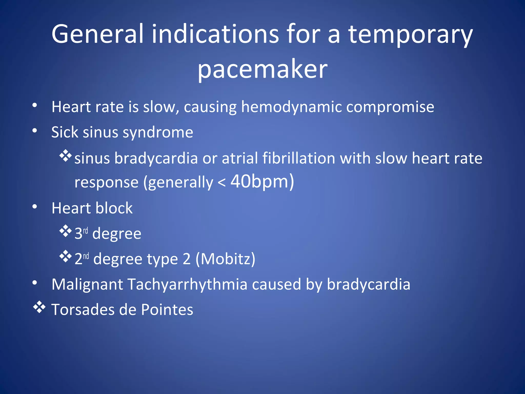
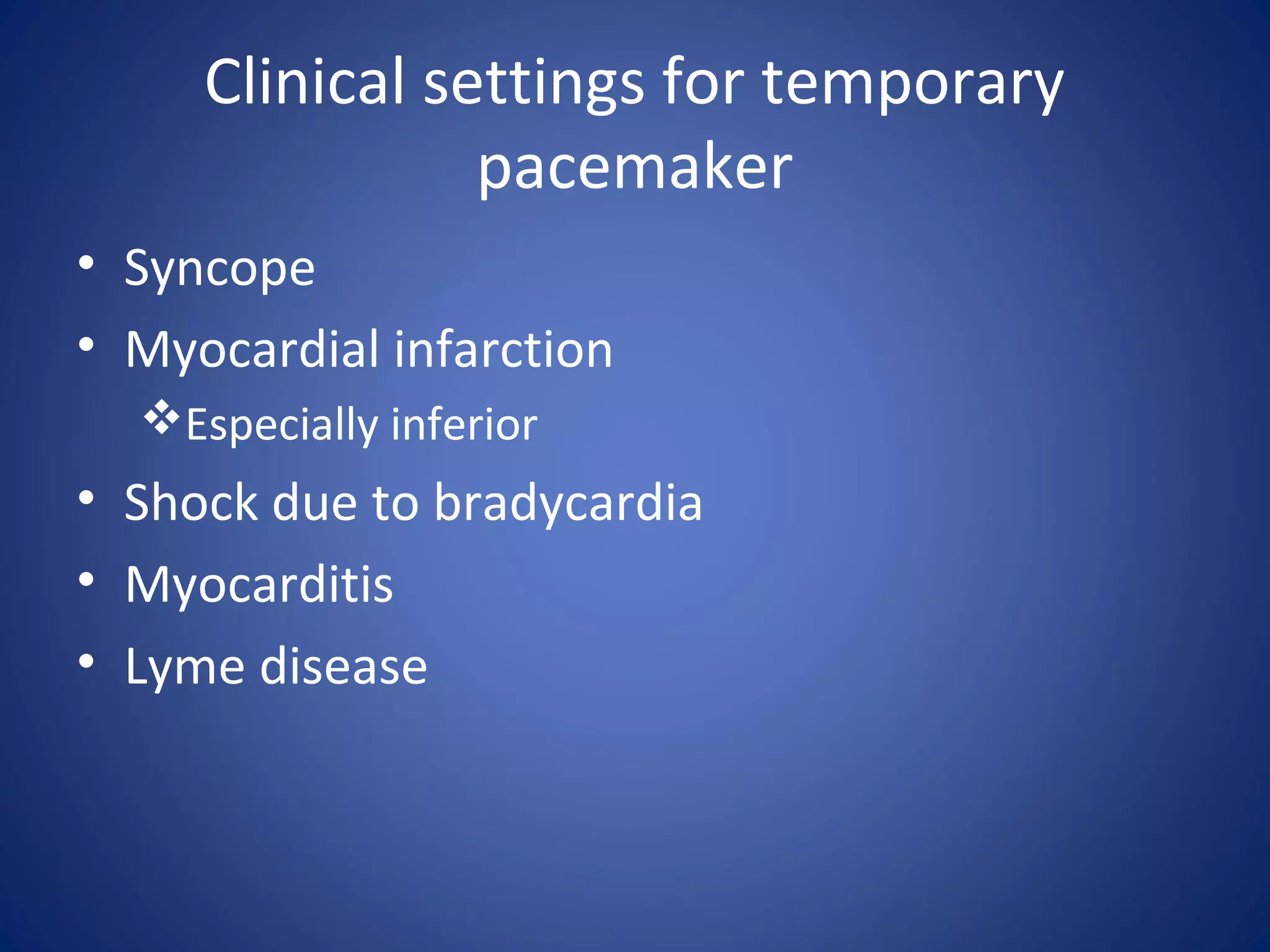
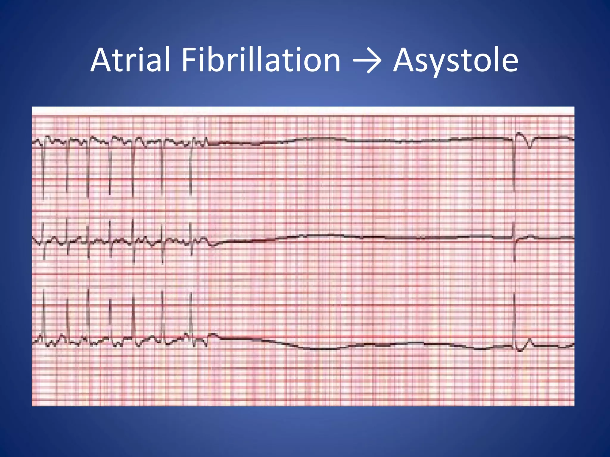
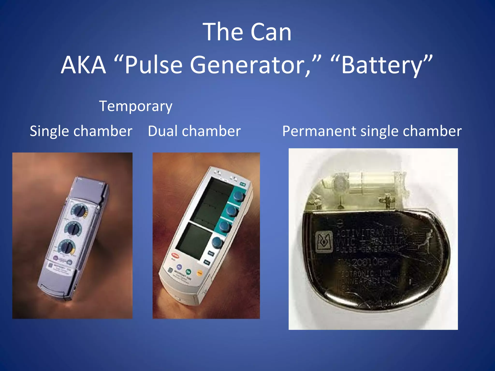
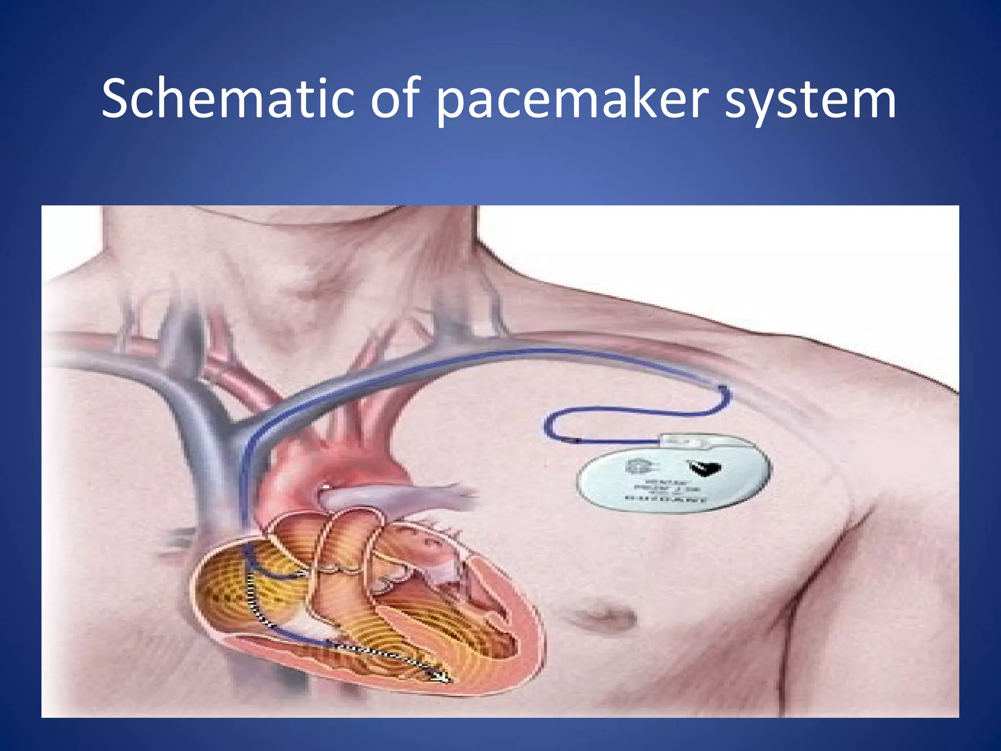
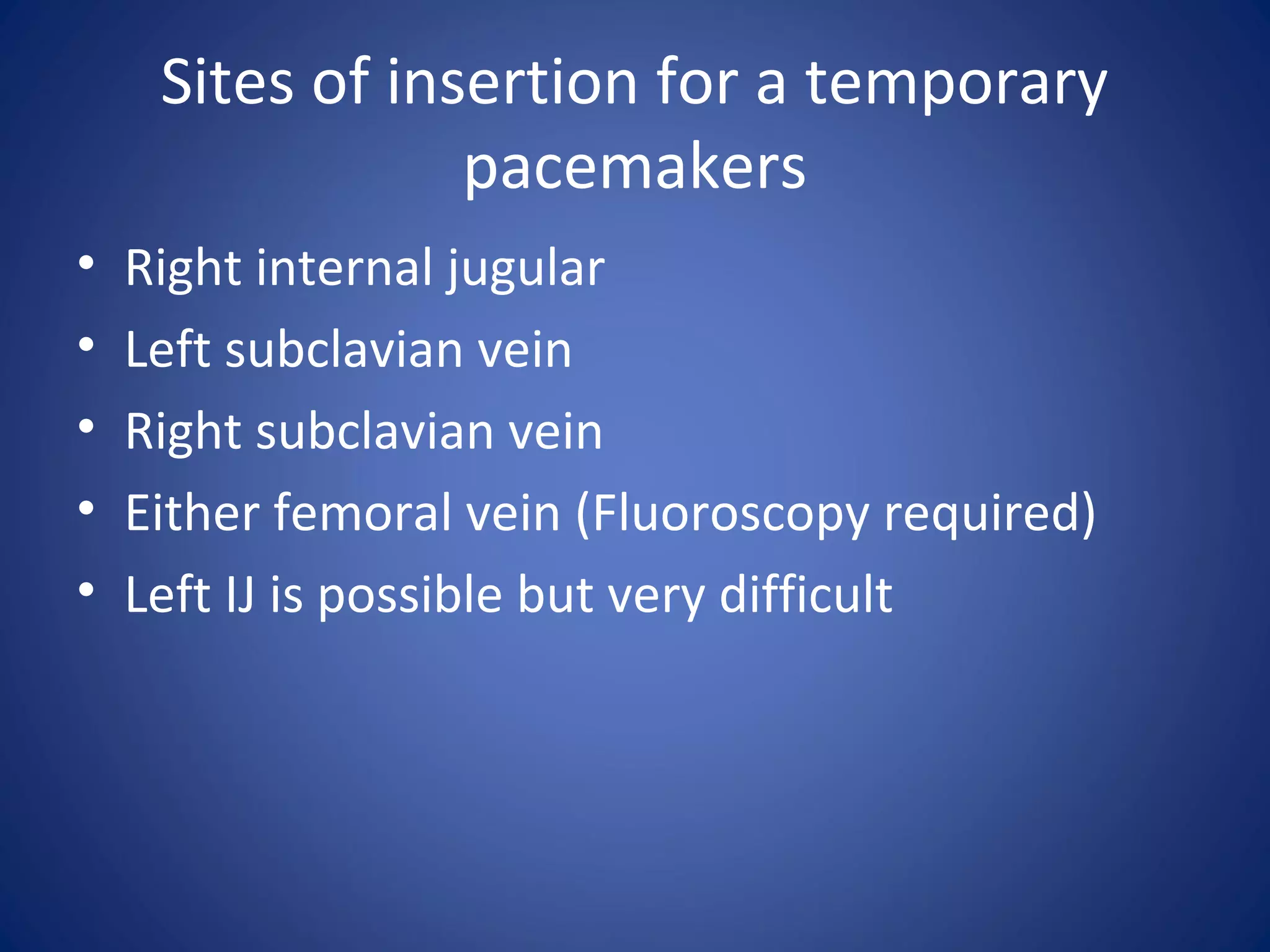
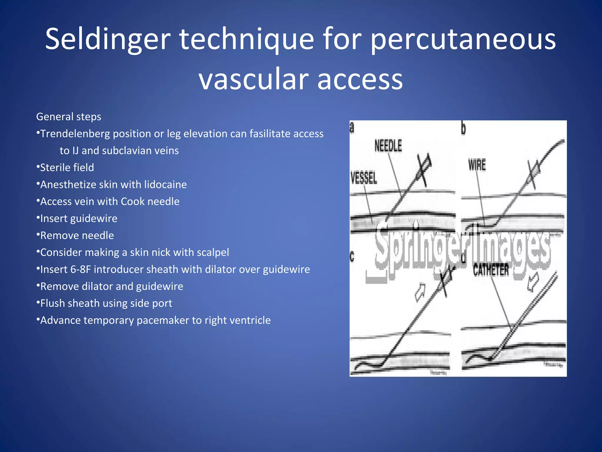
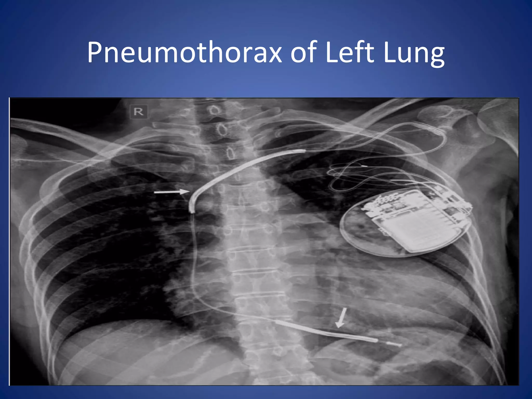


Temporary pacemakers are used to treat slow heart rates or heart block. They are inserted using the Seldinger technique into the internal jugular, subclavian, or femoral veins. A temporary pacemaker system includes leads that are placed in the heart and a pulse generator unit. Common complications include bleeding, infection, and pneumothorax. The unit has settings for rate, output, and sensitivity that must be tested and adjusted based on the patient's pacing and sensing thresholds.