Downloaded 91 times


![General Solution for Natural and Step Responses
of RL and RC Circuits
( t t0 )
x (t )
xf
[ x (t 0 )
x f ]e
Final Value
Time Constant
Initial Value
Determine the initial and final values of the
variable of interest and the time constant of the
circuit.
Substitute into the given expression.](https://image.slidesharecdn.com/stepnatural-140102082229-phpapp02/75/Step-natural-29-2048.jpg)


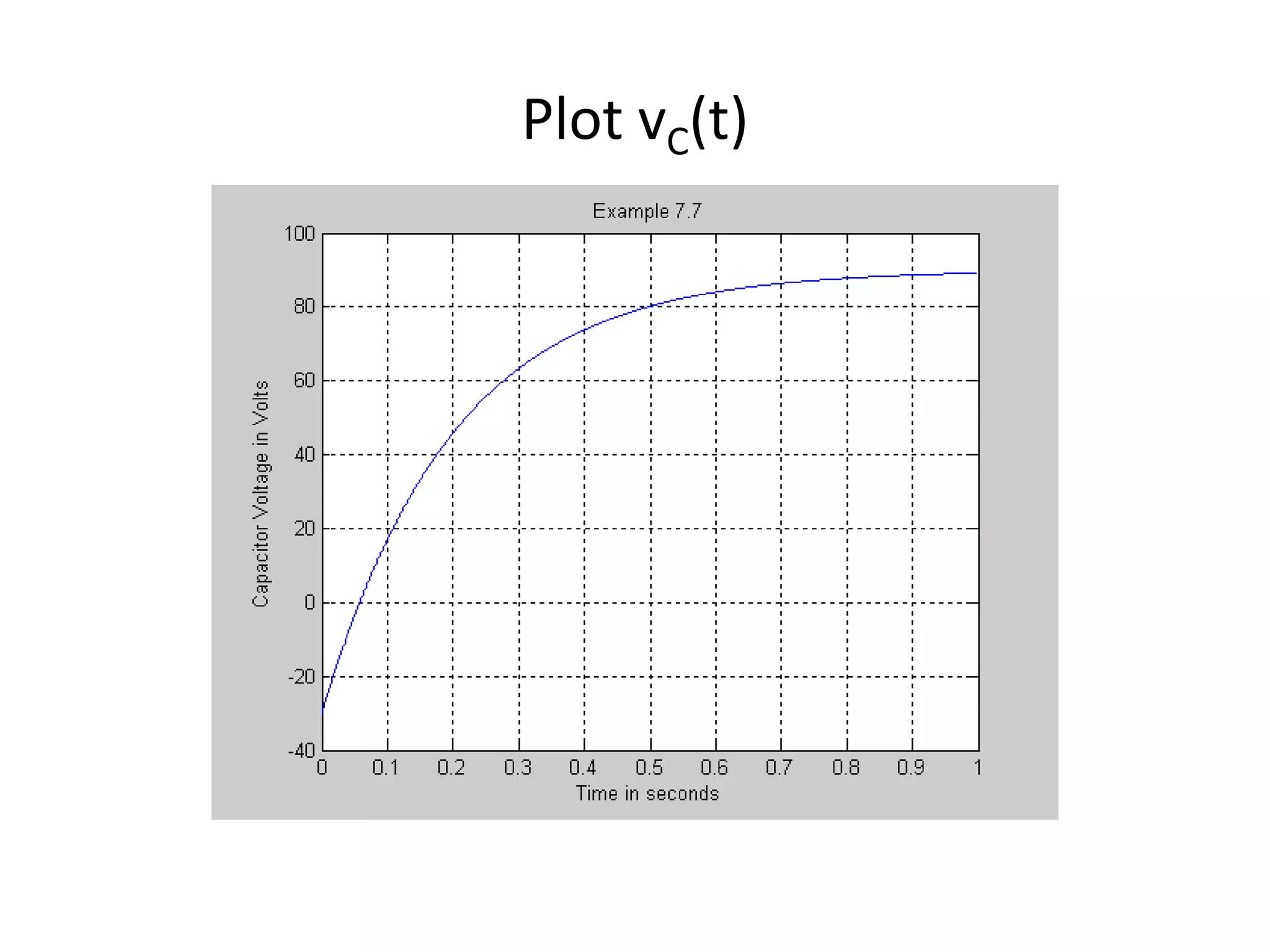
![The expression for vC(t) for t>=0
t
vC (t )
vC ( )
[ v C (0)
v C ( )]e
t
vC (t )
90
[ 30
vC (t )
90
120 e
90]e
5t
V
0.2](https://image.slidesharecdn.com/stepnatural-140102082229-phpapp02/75/Step-natural-34-2048.jpg)
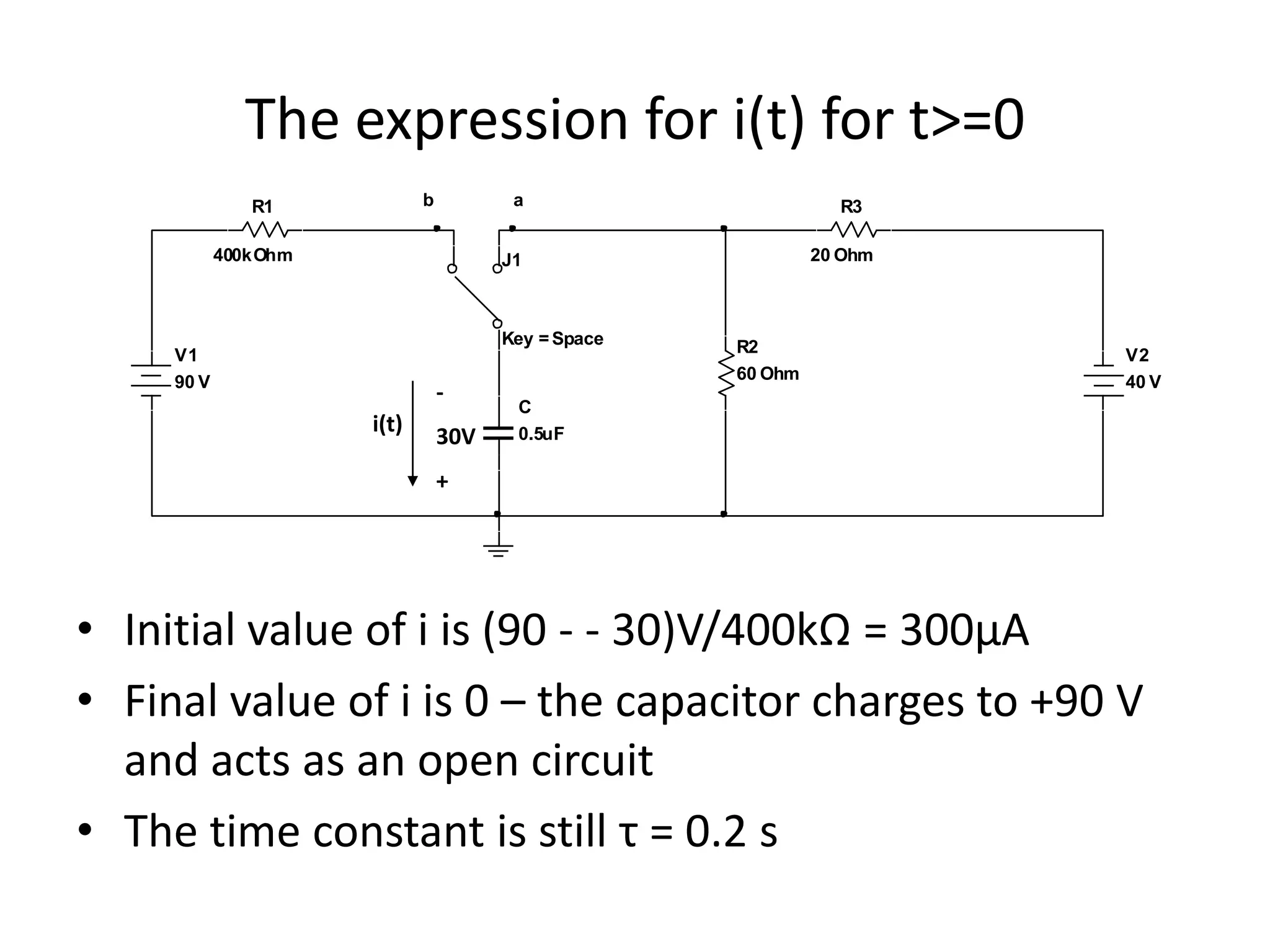
![The expression for i(t) (continued)
t
i (t )
i( )
[ i (0 )
i ( )]e
t
i (t )
i (t )
0
[300 10
300 e
5t
A
6
0] e
0.2](https://image.slidesharecdn.com/stepnatural-140102082229-phpapp02/75/Step-natural-36-2048.jpg)


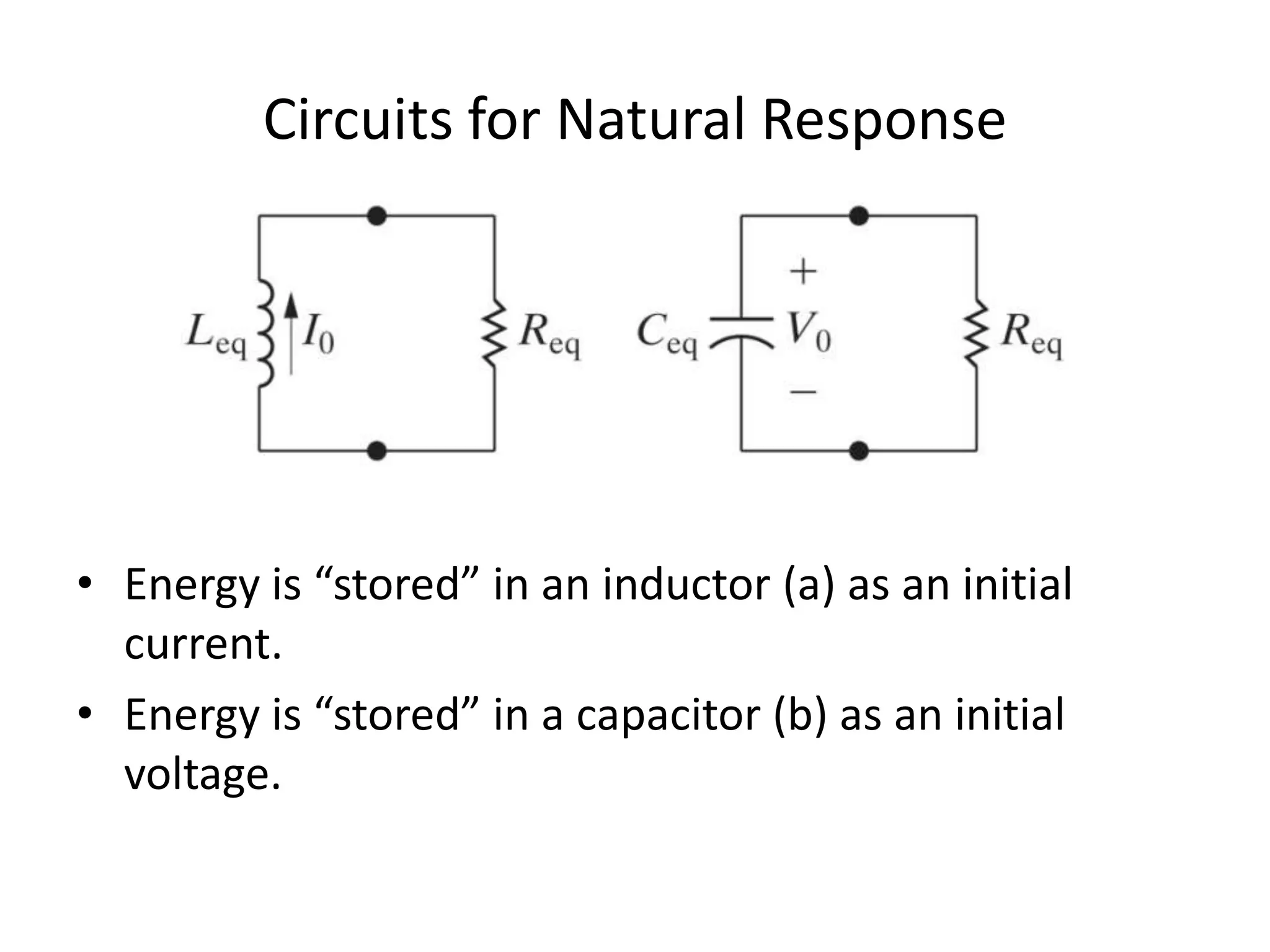
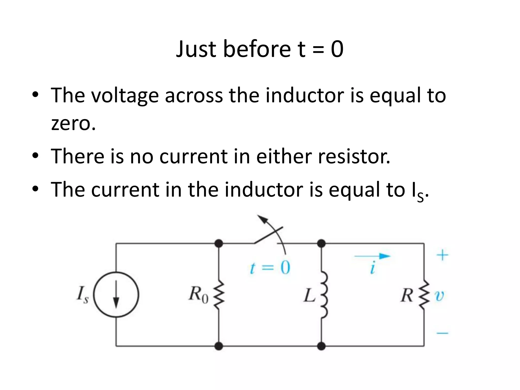
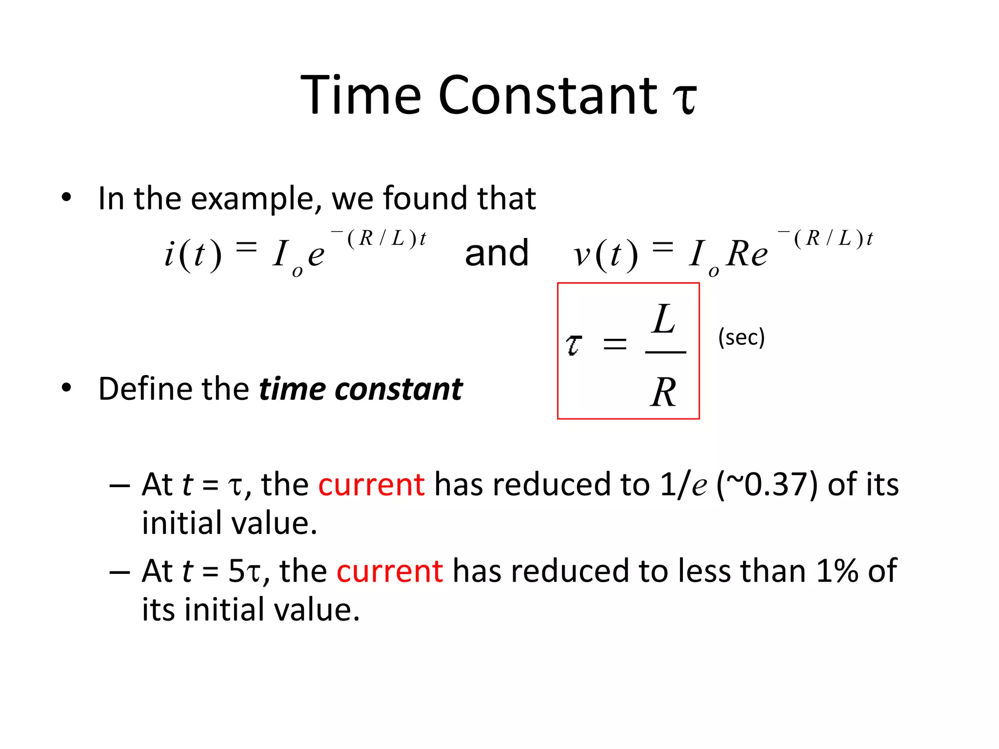
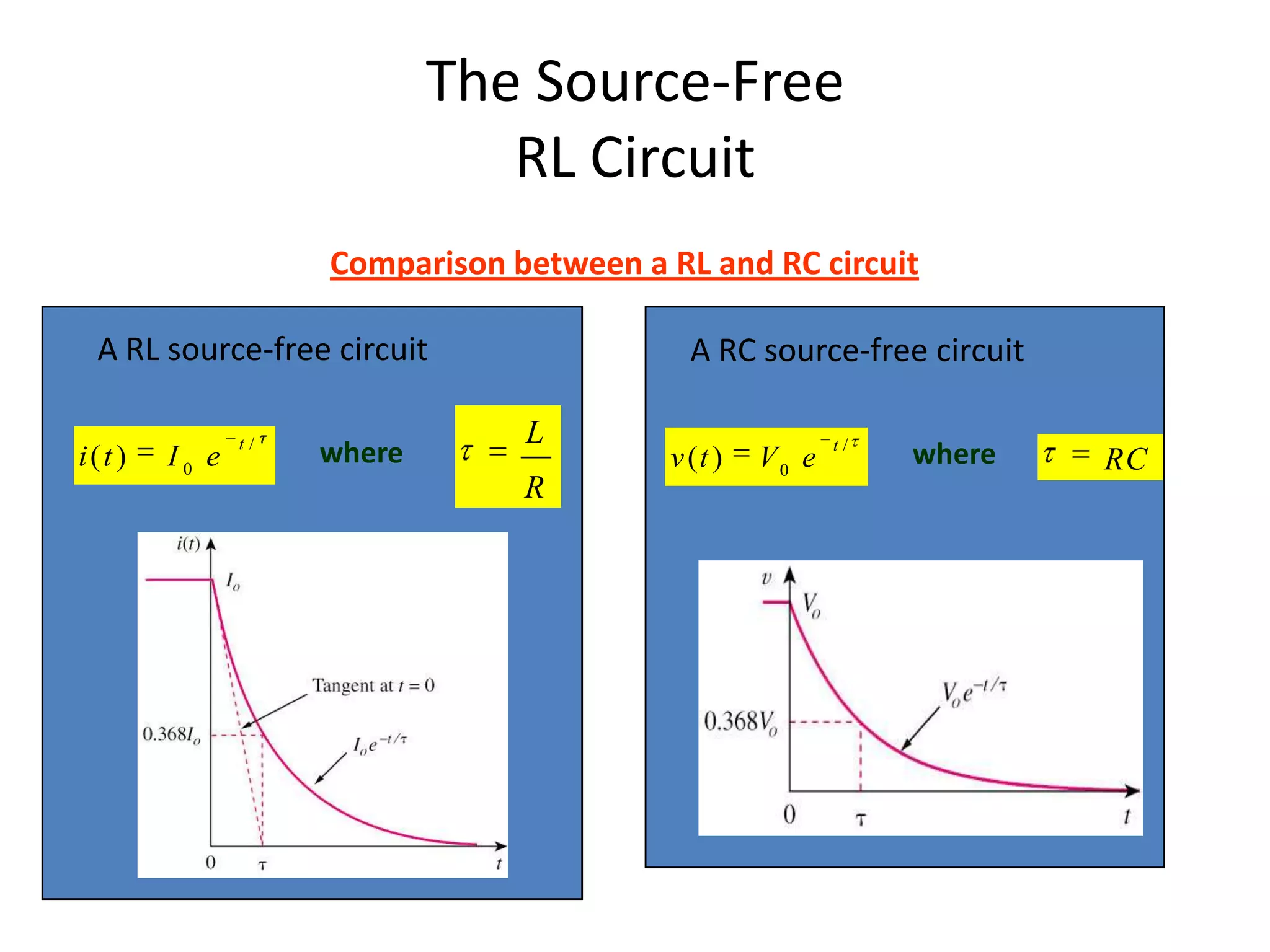
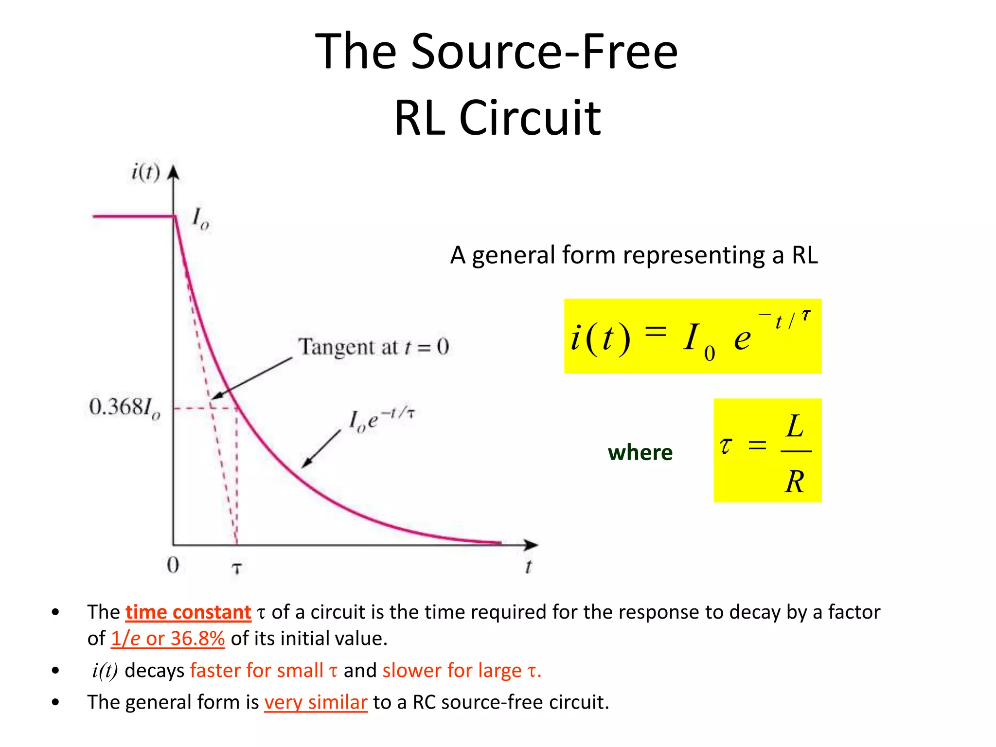
- The natural response of a circuit refers to the behavior of the circuit when external sources are removed. This allows the stored energy in inductors and capacitors to dissipate. - The general solution for the natural response of RL and RC circuits is an exponential decay from an initial value to a final value, with the decay rate determined by the circuit time constant. - For an RL circuit, the inductor current decays exponentially with time constant L/R. For an RC circuit, the capacitor voltage decays exponentially with time constant RC.