The document provides information on various electrical concepts:
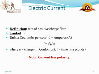
- Electric current is defined as the rate of positive charge flow and is measured in Amperes.
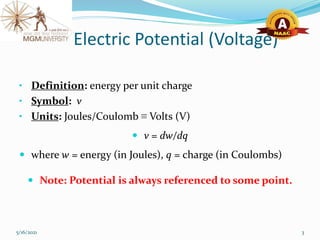
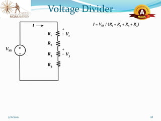
- Electric potential (voltage) is the energy per unit charge and is measured in Volts.
- Electric power is the transfer of energy per unit time and is measured in Watts.
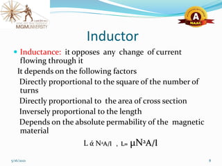
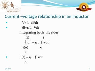
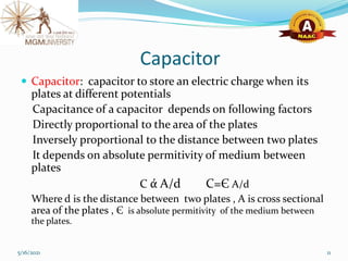
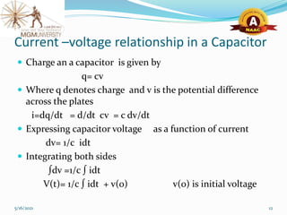
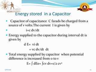
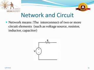
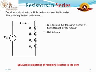
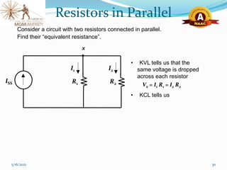
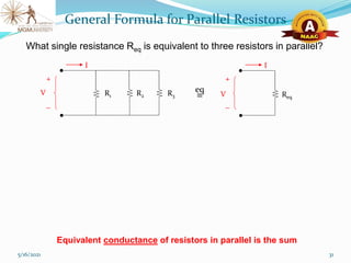
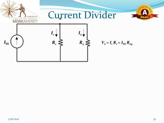
- Basic circuit elements are resistors, inductors, and capacitors. Resistors oppose current flow, inductors oppose changes in current, and capacitors store electric charge.


![UNIT-I Final (1)[1].pptfgcvhvjgbjhbjgbjhhvhvhvh](https://cdn.slidesharecdn.com/ss_thumbnails/unit-ifinal11-251129122433-e786871d-thumbnail.jpg?width=640&height=640&fit=bounds)