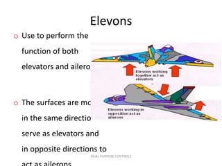
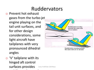
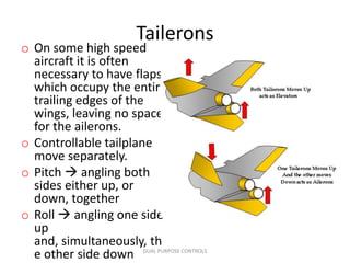
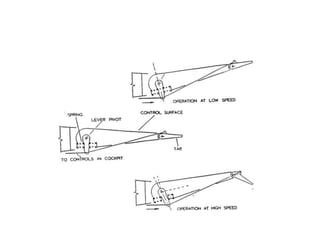
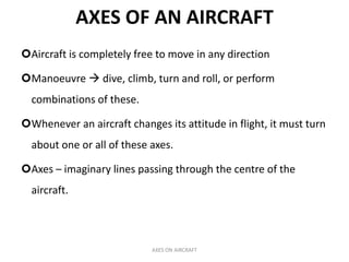
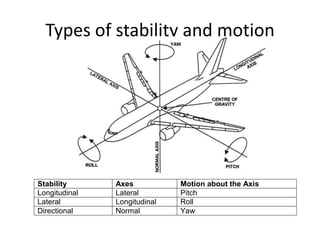
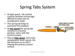
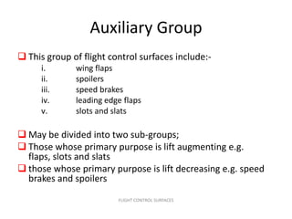
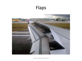
The document discusses the stability and dynamics of an aircraft, focusing on its three axes: longitudinal, lateral, and vertical. It details how control surfaces like ailerons, elevators, and rudders manage aircraft attitude and stability in flight, as well as various types of stability and motion associated with these axes. Additionally, it outlines flight control surfaces' function, including primary, secondary, and auxiliary groups, and explains how different flaps and high-lift devices enhance performance during takeoff and landing.

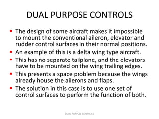
![Plain flaps
• Retracted to form a
complete section of the
wing trailing edge
• When in use it is hinged
downwards
FLIGHT CONTROL SURFACES [Auxiliary Group]](https://image.slidesharecdn.com/8-4-120801195559-phpapp02/85/EASA-PART-66-MODULE-8-4-FLIGHT-STABILITY-AND-DYNAMICS-47-320.jpg)
![Split flap
• This flap is hinged at the
lower part of the wing
trailing edge.
• When lowered, the wing
top surface is
unchanged, thus
eliminating the airflow
break-away like what
occurring over the top of
the plain flap when
lowering
FLIGHT CONTROL SURFACES [Auxiliary
Group]](https://image.slidesharecdn.com/8-4-120801195559-phpapp02/85/EASA-PART-66-MODULE-8-4-FLIGHT-STABILITY-AND-DYNAMICS-48-320.jpg)
![Zap Flap
• Similar to the split flap
except that the flap hinge
travels rearward when
lowered
• Increases wing effective
area as well as its camber
without changing the
shape of the top surface
• Like the split flap there is
little risk of flow
separation on top of the
wing
FLIGHT CONTROL SURFACES [Auxiliary
Group]](https://image.slidesharecdn.com/8-4-120801195559-phpapp02/85/EASA-PART-66-MODULE-8-4-FLIGHT-STABILITY-AND-DYNAMICS-49-320.jpg)
![Fowler Flap
• The fowler is similar to
the split flap but, when
in use, it is moved
rearwards and
downwards on tracks.
• This action will increase
the wing camber and
also the wing area to
give additional lift.
FLIGHT CONTROL SURFACES [Auxiliary
Group]](https://image.slidesharecdn.com/8-4-120801195559-phpapp02/85/EASA-PART-66-MODULE-8-4-FLIGHT-STABILITY-AND-DYNAMICS-50-320.jpg)
![Slotted Flap
• A gap or slot formed between
the flap and the wing structure
• Air will flow from the wing
lower surface, through the gap
and over the top of the flap
• This airflow will maintain lift
by speeding up as it passes
through the slot and
remaining in contact with the
flat top surface, even at large
flap angles
• Without the slot the upper
surface airflow would break
away
FLIGHT CONTROL SURFACES [Auxiliary
Group]](https://image.slidesharecdn.com/8-4-120801195559-phpapp02/85/EASA-PART-66-MODULE-8-4-FLIGHT-STABILITY-AND-DYNAMICS-51-320.jpg)
![Slotted Flap
FLIGHT CONTROL SURFACES [Auxiliary
Group]](https://image.slidesharecdn.com/8-4-120801195559-phpapp02/85/EASA-PART-66-MODULE-8-4-FLIGHT-STABILITY-AND-DYNAMICS-52-320.jpg)
![Slotted Fowler Flap
• A Fowler flap with slot
• Multi-slotted on
improved design
• Increase camber and
area
• The breakaway of the
airflow from the flap
upper surface can be
delayed until even greater
angles of flap depression
by providing two or more
slots
FLIGHT CONTROL SURFACES [Auxiliary
Group]](https://image.slidesharecdn.com/8-4-120801195559-phpapp02/85/EASA-PART-66-MODULE-8-4-FLIGHT-STABILITY-AND-DYNAMICS-53-320.jpg)
![Slotted Fowler Flap
FLIGHT CONTROL SURFACES [Auxiliary
Group]](https://image.slidesharecdn.com/8-4-120801195559-phpapp02/85/EASA-PART-66-MODULE-8-4-FLIGHT-STABILITY-AND-DYNAMICS-54-320.jpg)
![Leading edge flap
• Referred as Krueger’s Flap
• To increase lift at low speed
• Increase camber increase
lift
• Leading and trailing edge
flaps are normally coupled
to operate together
• May be lowered
automatically when the
aircraft’s speed falls to near
the stalling speed
FLIGHT CONTROL SURFACES [Auxiliary
Group]](https://image.slidesharecdn.com/8-4-120801195559-phpapp02/85/EASA-PART-66-MODULE-8-4-FLIGHT-STABILITY-AND-DYNAMICS-55-320.jpg)
![Slats
• For low speed operation
other than take-off or
landing
• A small, highly-cambered
airfoils fitted to the wing
leading edges
• May be fixed open, or
controlled to operate alone
or jointly with the flaps
• Some aircraft have slats
which open automatically
when the wing angle of
attack exceeds a
predetermined value
FLIGHT CONTROL SURFACES [Auxiliary
Group]](https://image.slidesharecdn.com/8-4-120801195559-phpapp02/85/EASA-PART-66-MODULE-8-4-FLIGHT-STABILITY-AND-DYNAMICS-56-320.jpg)
![Slats
FLIGHT CONTROL SURFACES [Auxiliary
Group]](https://image.slidesharecdn.com/8-4-120801195559-phpapp02/85/EASA-PART-66-MODULE-8-4-FLIGHT-STABILITY-AND-DYNAMICS-57-320.jpg)
![Slot
• Is a series of suitably
shaped apertures built
into the wing structure
near the wing tips
• It increase the stalling
angle by guiding and
accelerating air from
below the wing and
discharging it over the
upper surface in the
normal way
FLIGHT CONTROL SURFACES [Auxiliary
Group]](https://image.slidesharecdn.com/8-4-120801195559-phpapp02/85/EASA-PART-66-MODULE-8-4-FLIGHT-STABILITY-AND-DYNAMICS-58-320.jpg)
![Airbrakes/Speed brakes
• Movable panels forming part
of the contour of the wings or
fuselage
• Deflected into the airflow by
hydraulic actuators to give a
rapid reduction in speed when
is required.
• Used to control speed during
descent and landing approach
• Installed on the strongest
airframe structure able to
accept the braking loads and
also where the braking drag
does not effect the aircraft
stability
FLIGHT CONTROL SURFACES [Auxiliary
Group]](https://image.slidesharecdn.com/8-4-120801195559-phpapp02/85/EASA-PART-66-MODULE-8-4-FLIGHT-STABILITY-AND-DYNAMICS-59-320.jpg)
![Spoilers
• Are plates fitted to the
upper surface of the wing
and usually deflected
upward by hydraulic
actuators
• The purpose is to disturb
the smooth airflow across
the top of the
wing, thereby increasing
drag and decreased lift on
that aircraft
FLIGHT CONTROL SURFACES [Auxiliary
Group]](https://image.slidesharecdn.com/8-4-120801195559-phpapp02/85/EASA-PART-66-MODULE-8-4-FLIGHT-STABILITY-AND-DYNAMICS-60-320.jpg)