Download as PDF, PPTX


The document discusses mechatronic system simulation as an approach to modeling and analyzing multi-domain systems that integrate mechanical, electronic, control, and software engineering, focusing on their interconnectedness and behavior. It highlights the use of LMS Imagine.Lab Amesim for creating system models to optimize performance and predict behavior while facilitating design decisions across varied industries including automotive and aerospace. Key concepts include one-dimensional computer-aided engineering (1D CAE), multidisciplinary modeling, and the importance of power flow and conservation in dynamic systems.
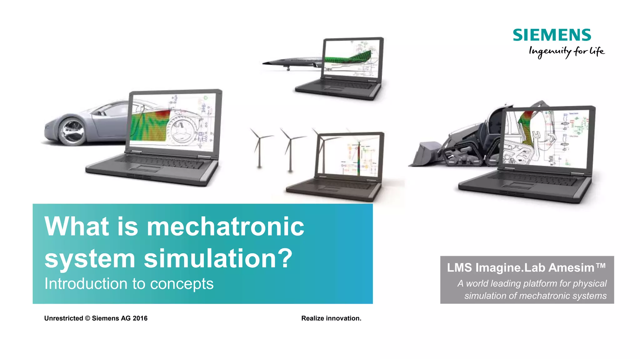
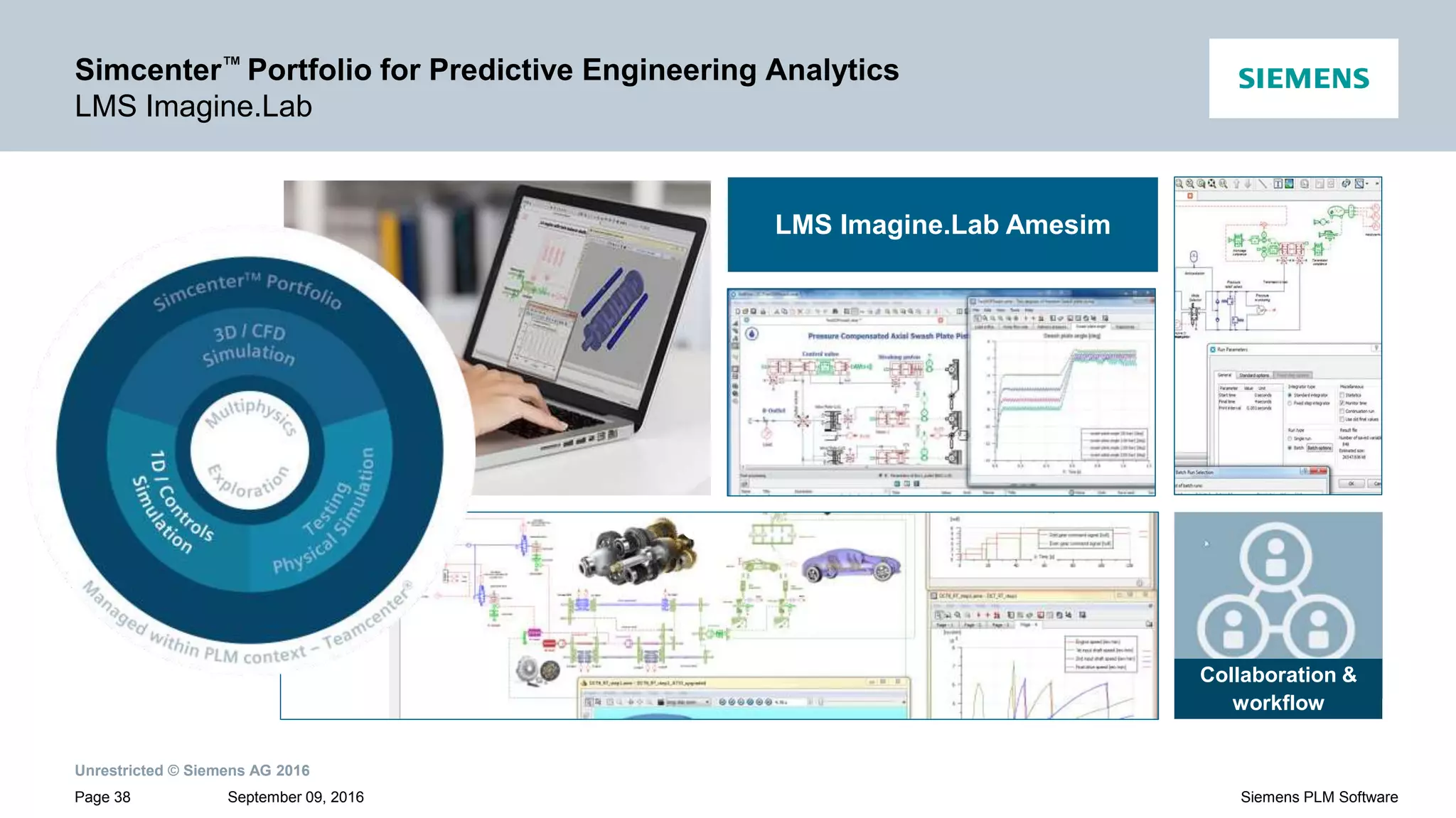
Introduces mechatronic system simulation and LMS Imagine.Lab Amesim as a leading physical simulation platform.
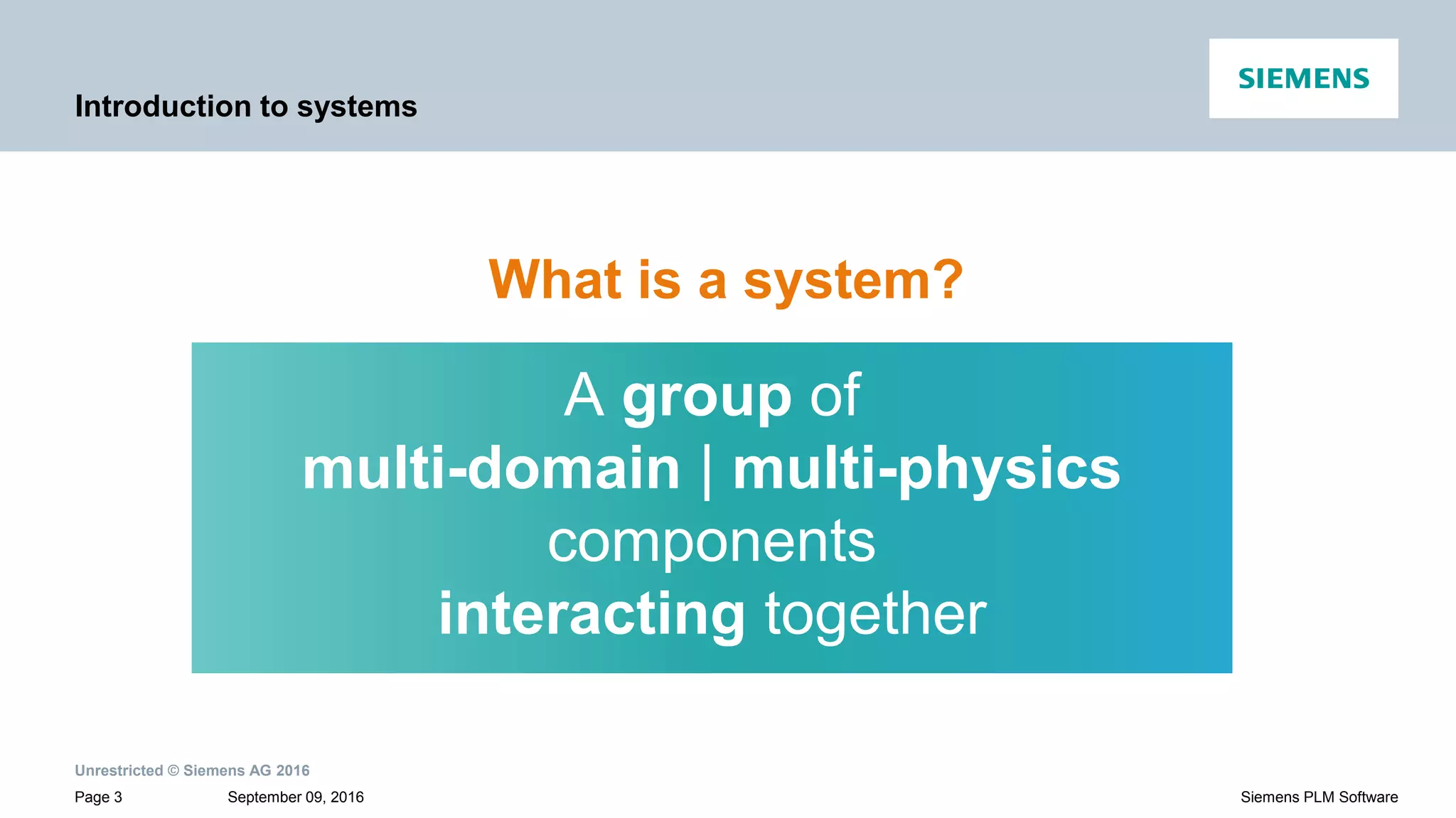
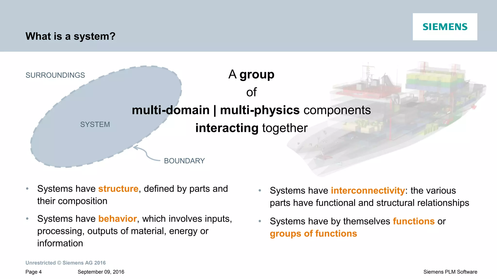
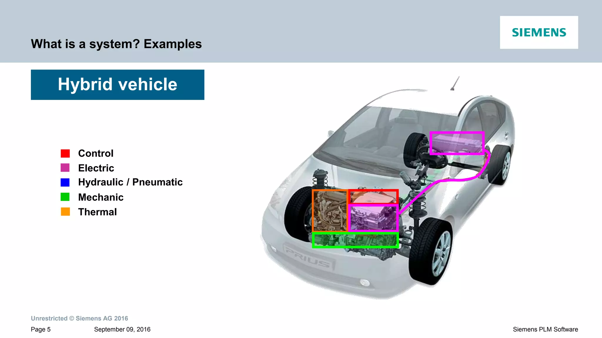
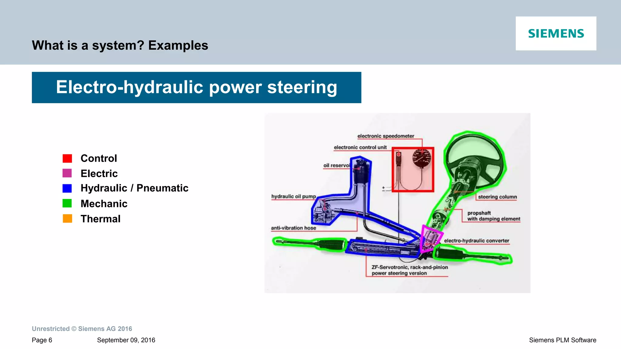
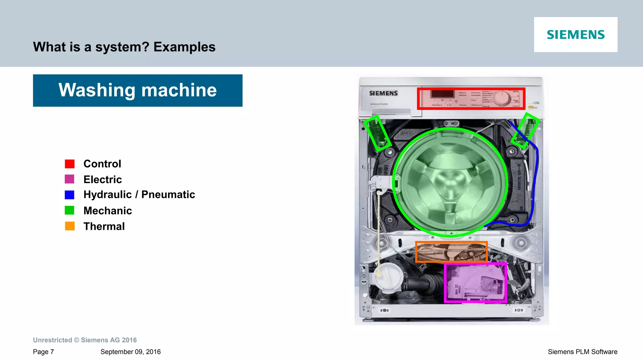
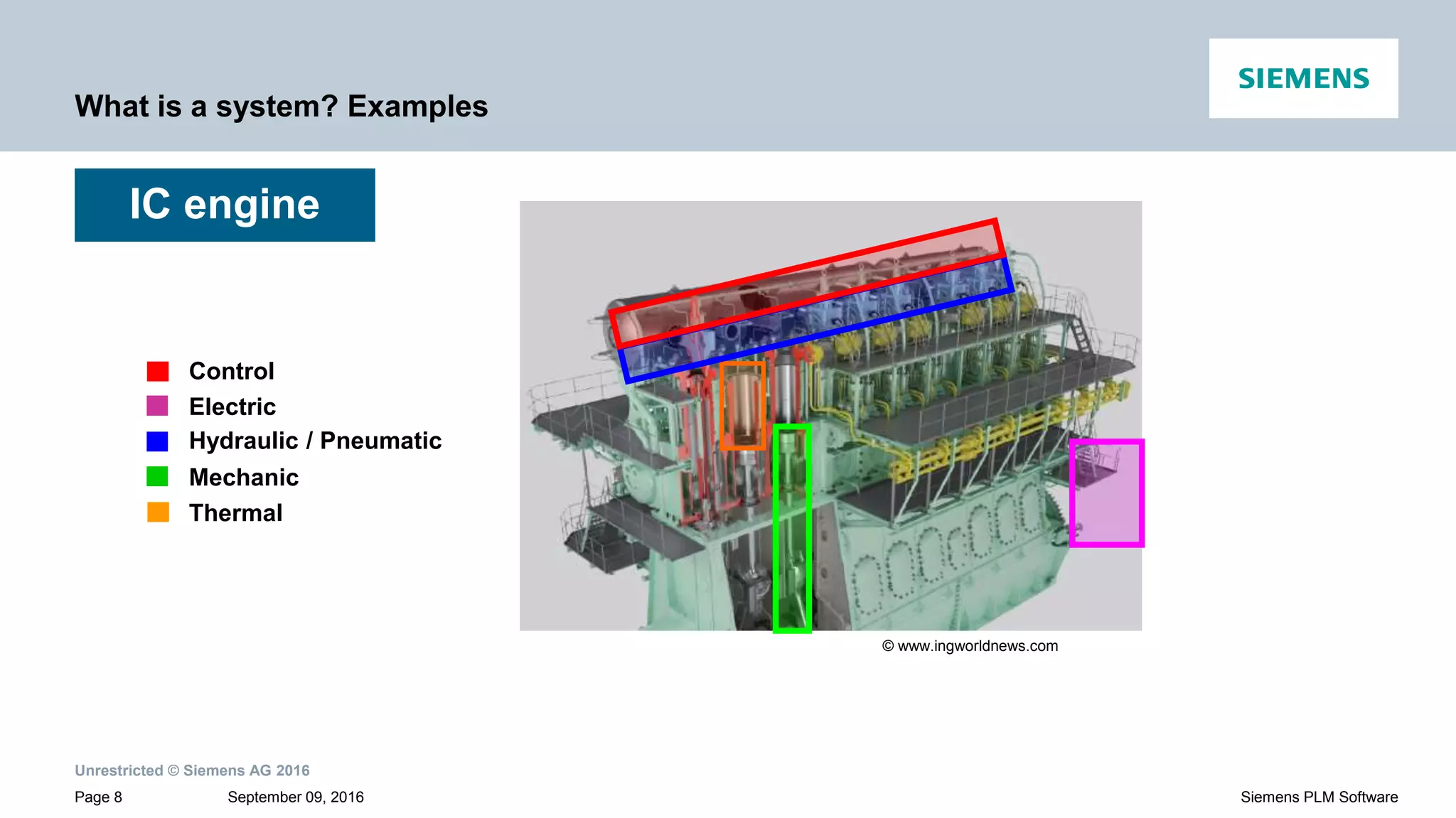
Defines a system with interconnectivity and provides examples including hybrid vehicles, washing machines, and IC engines.
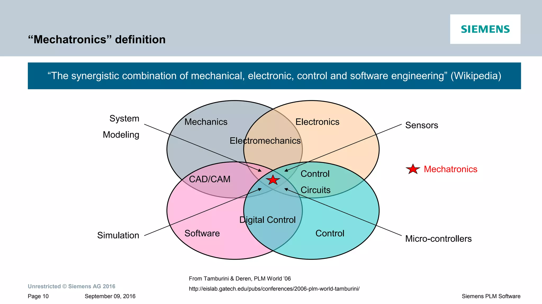
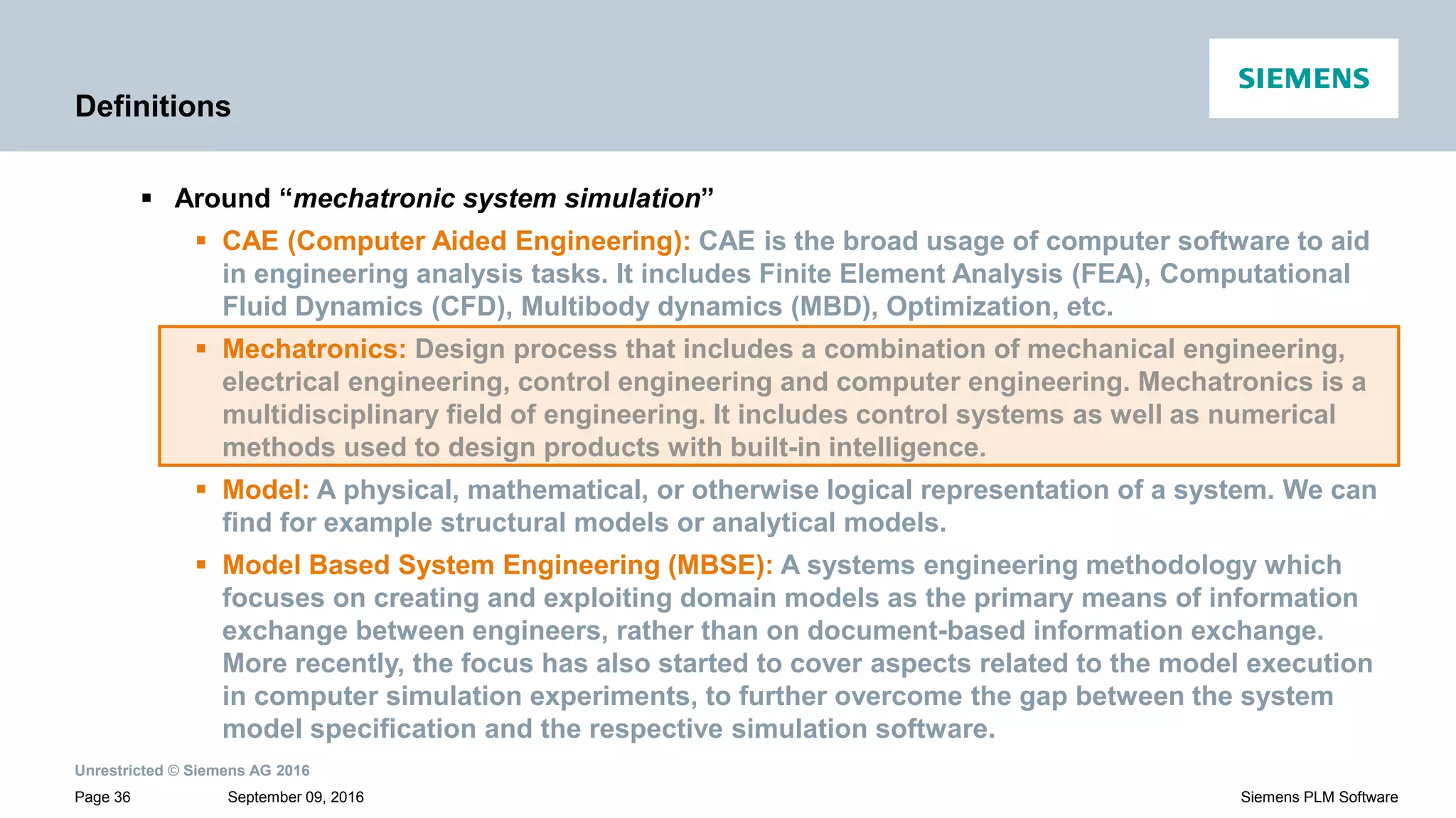
Presents the definition of mechatronics as a combination of mechanical, electronic, and control engineering.
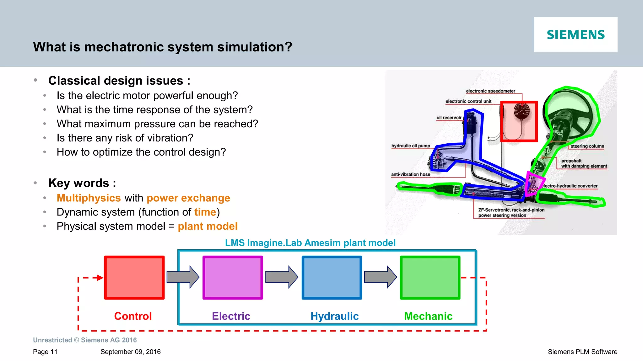
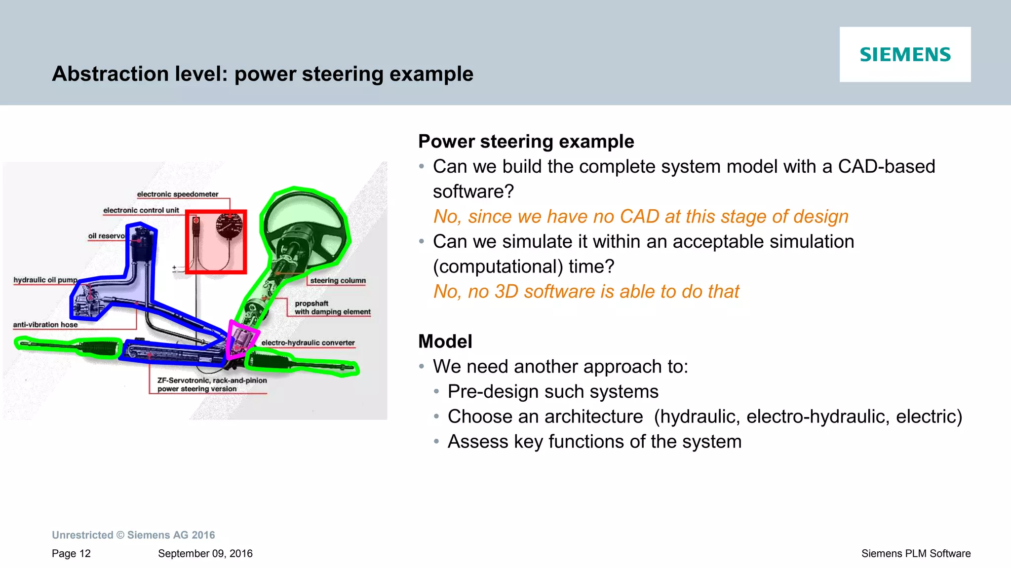
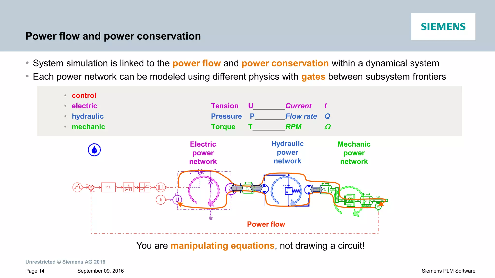
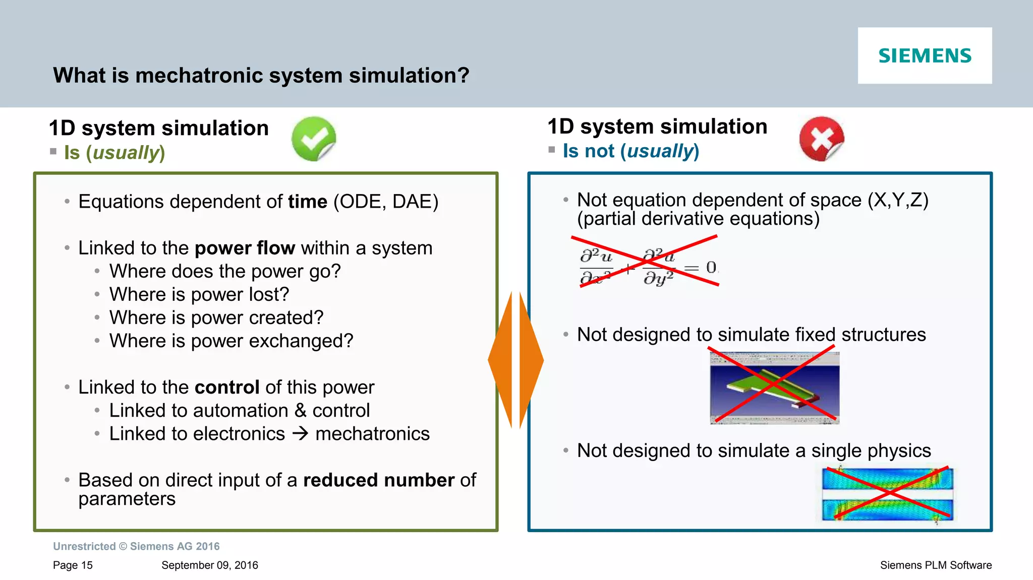
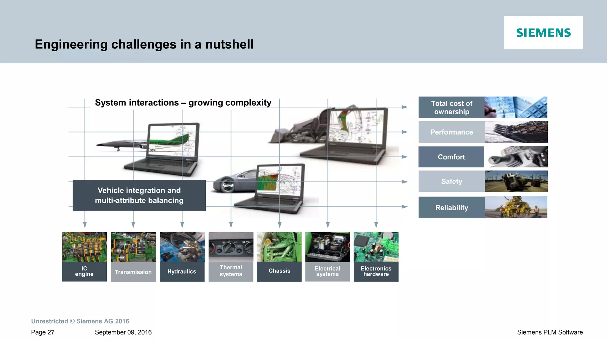
Discusses mechatronic system simulation focusing on classical design issues, power flow and dynamics, and 1D system simulation.
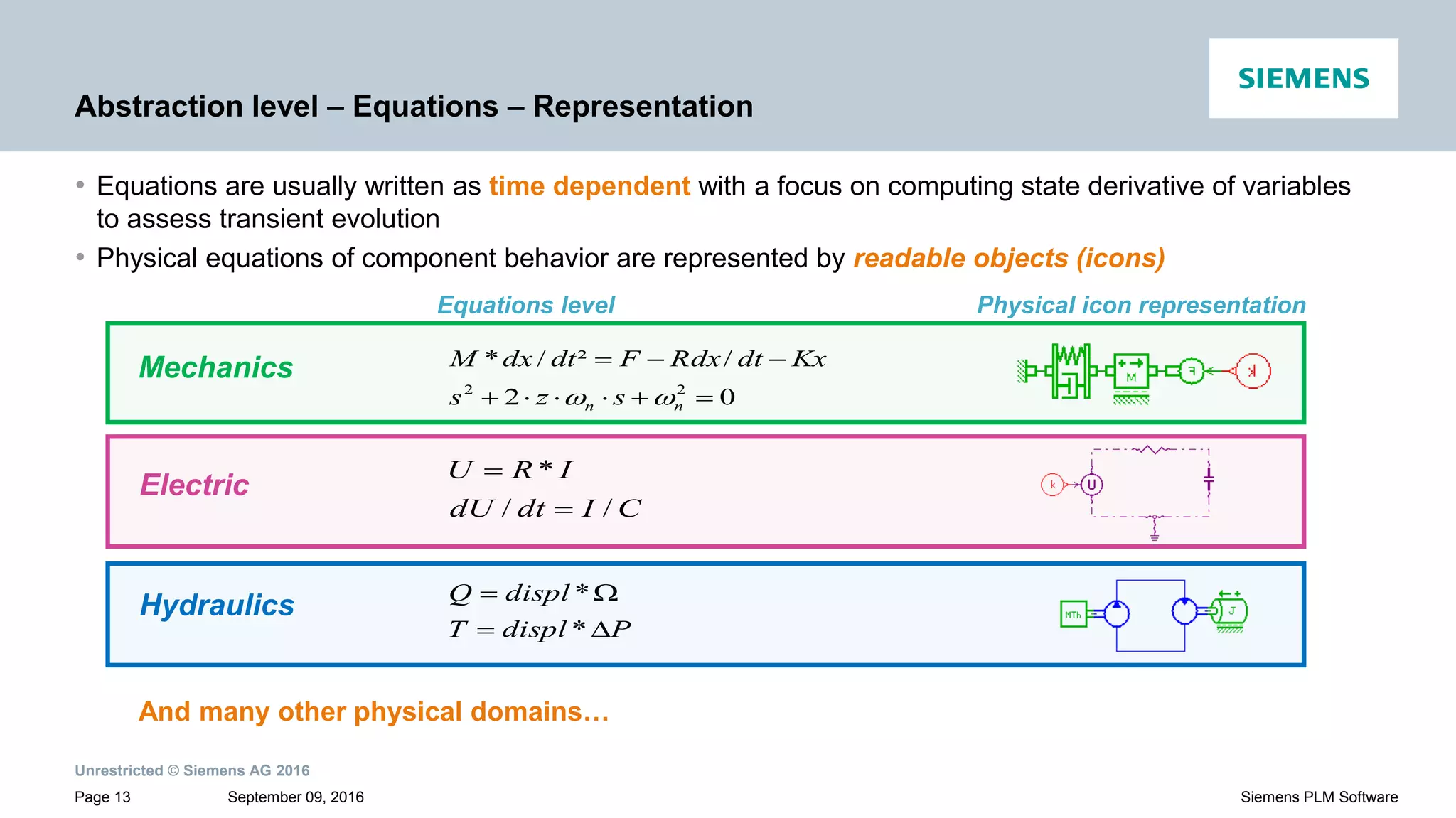
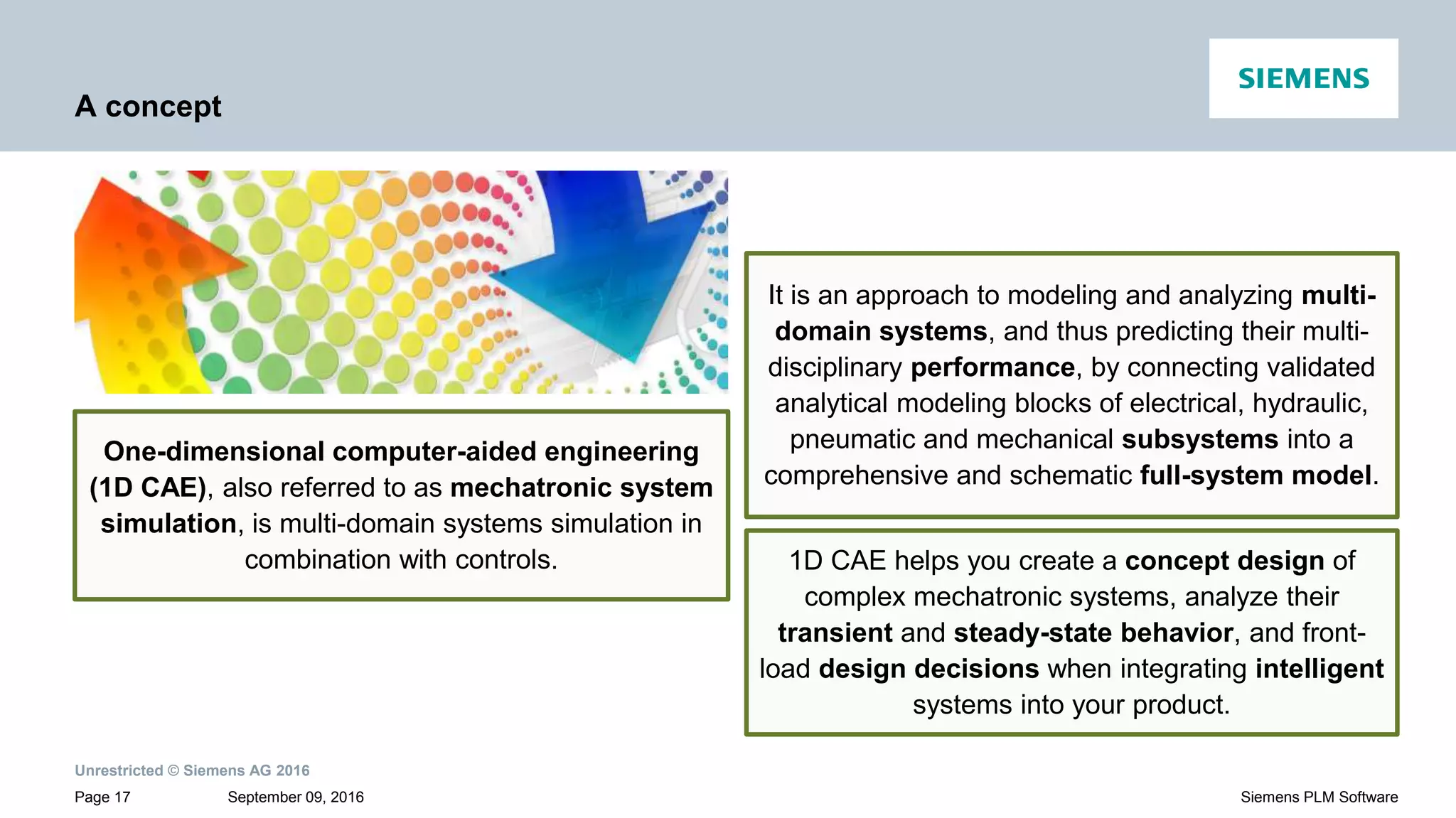
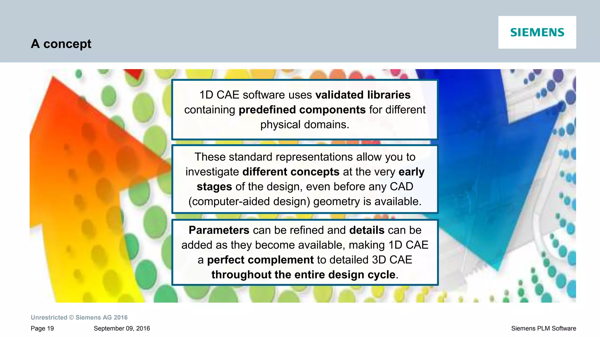
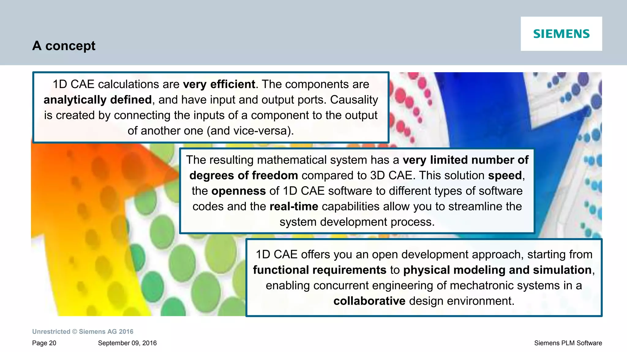
Explains 1D computer-aided engineering (CAE) for modeling multi-domain systems, enabling early design analysis.
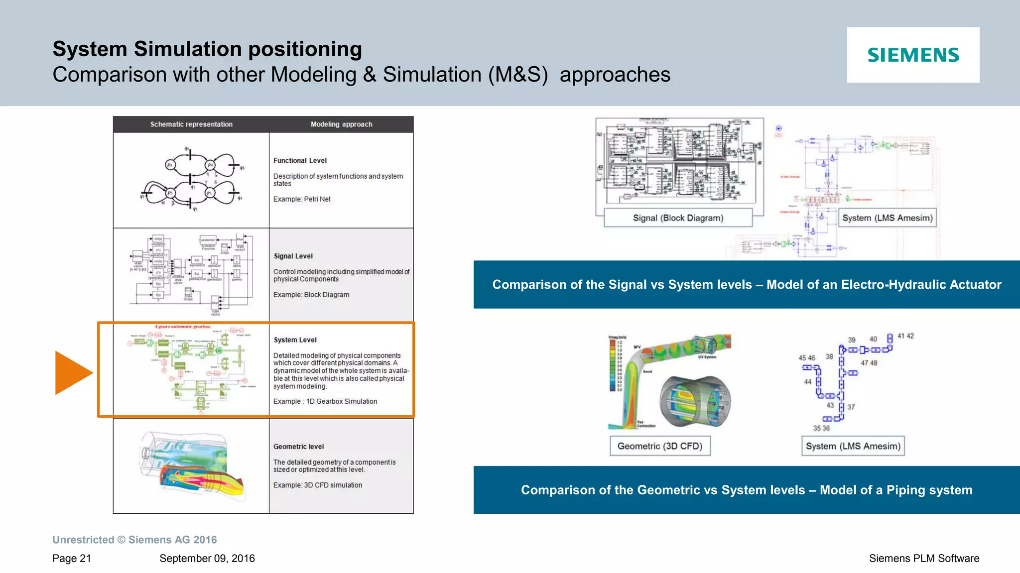
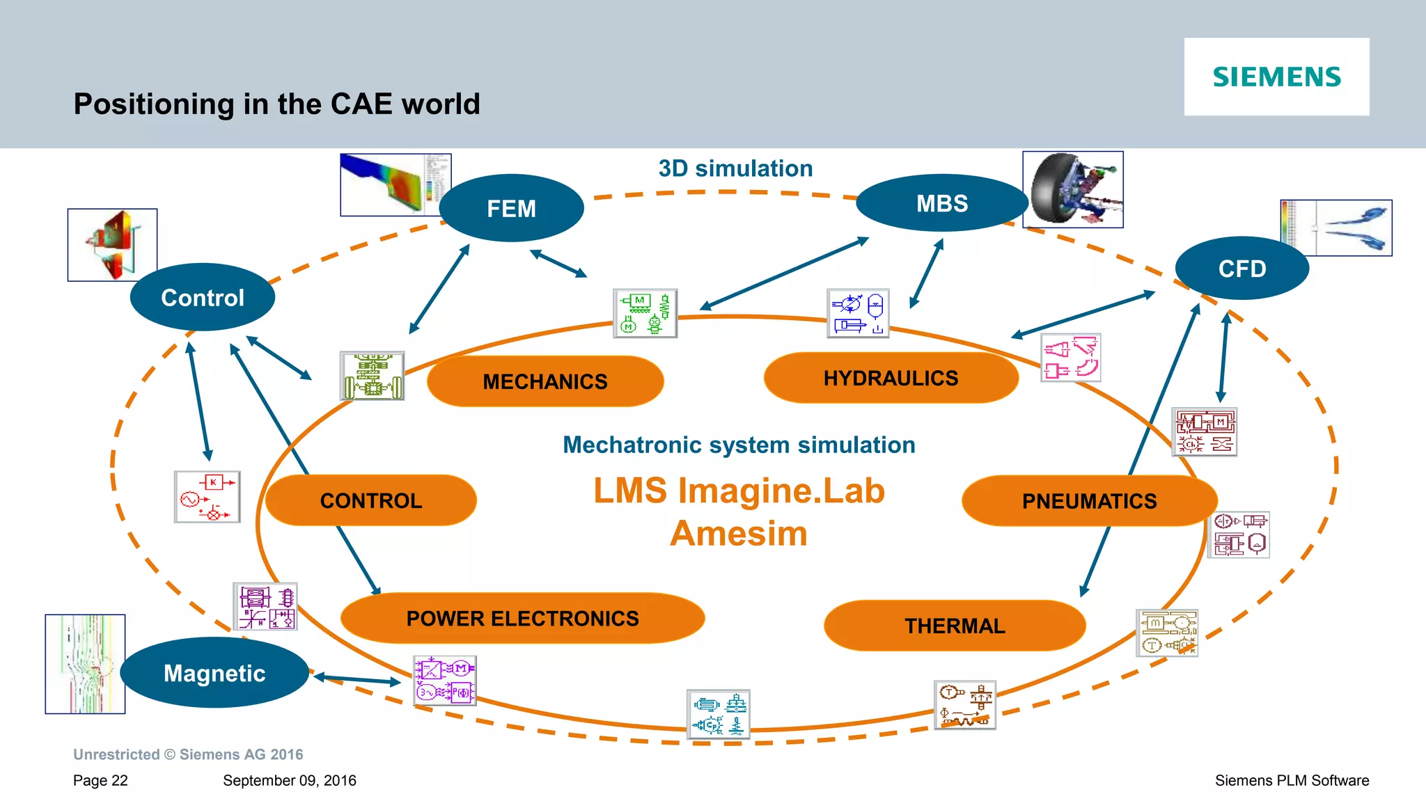
Positions mechatronic system simulation within the landscape of other modeling and simulation approaches.
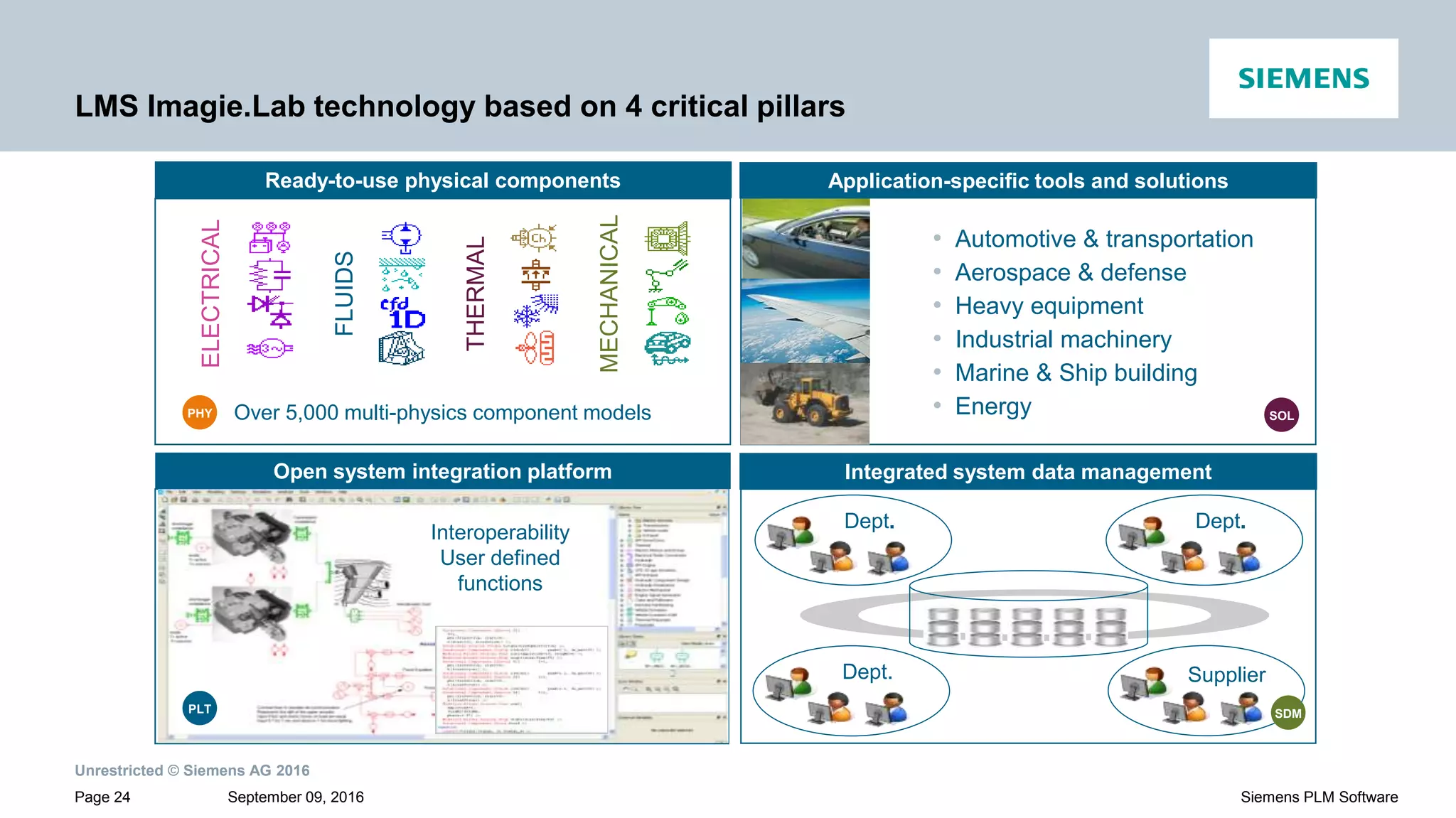
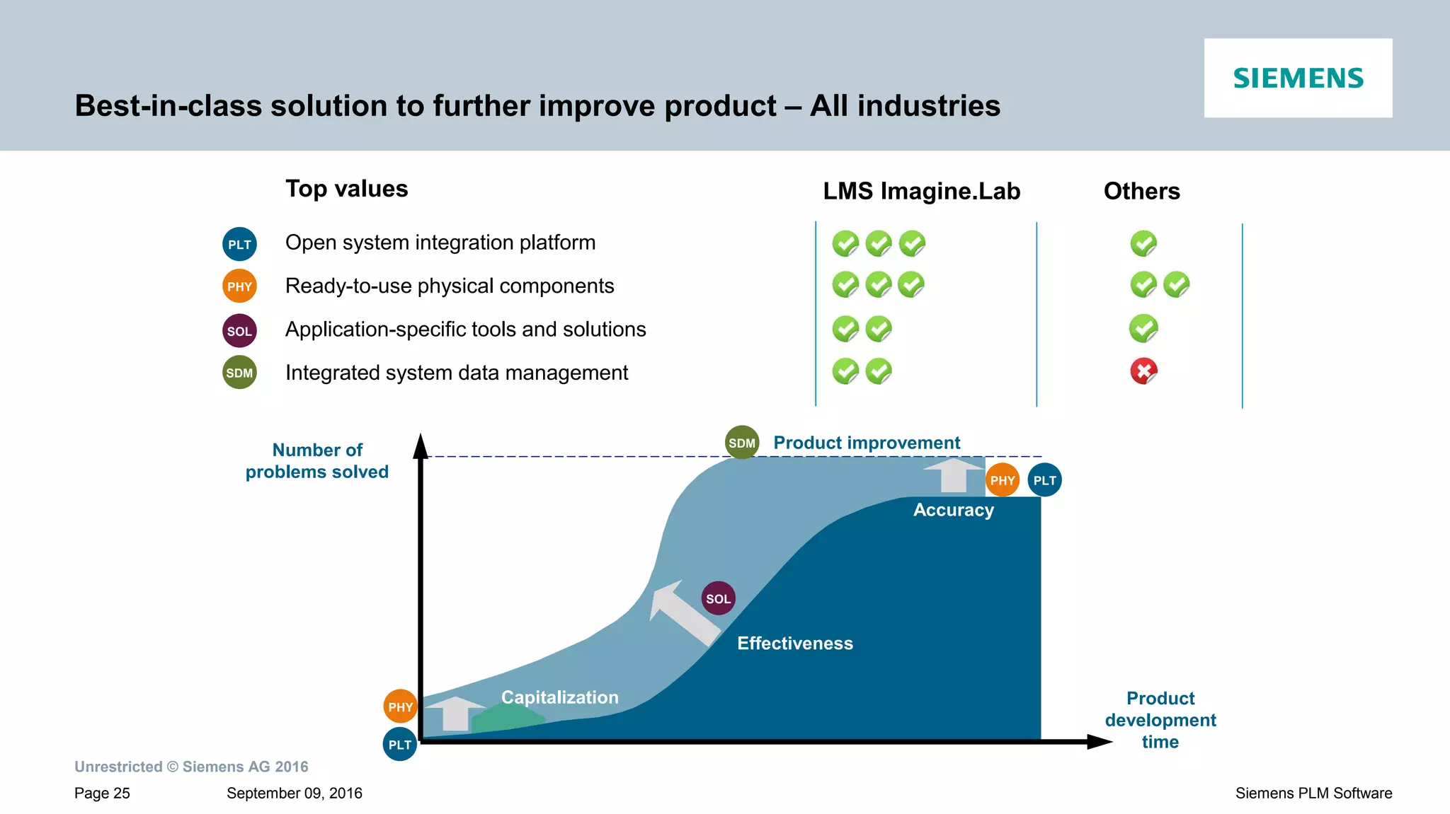
Highlights LMS Imagine.Lab technology based on physical components and industry-specific solutions.
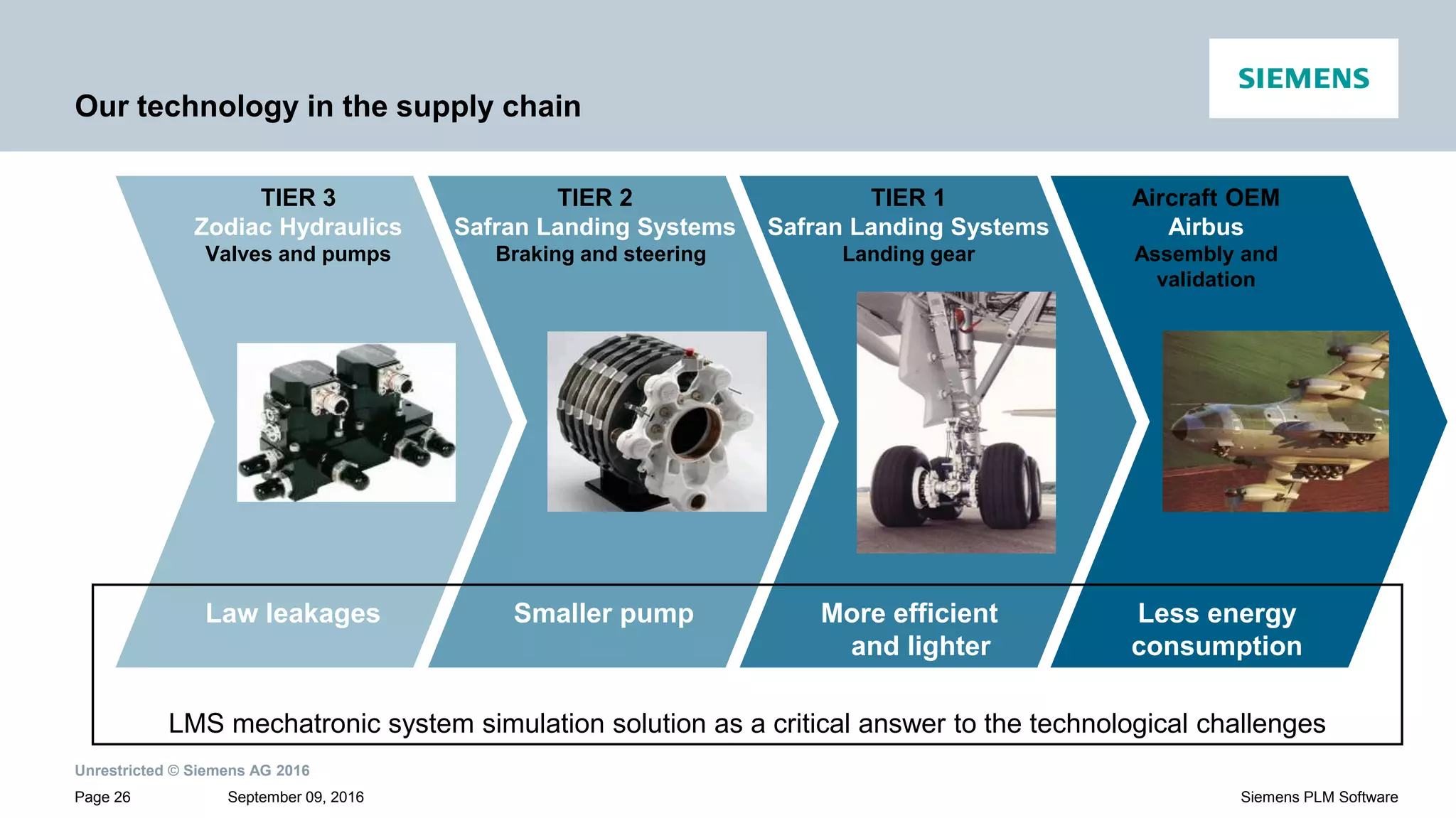
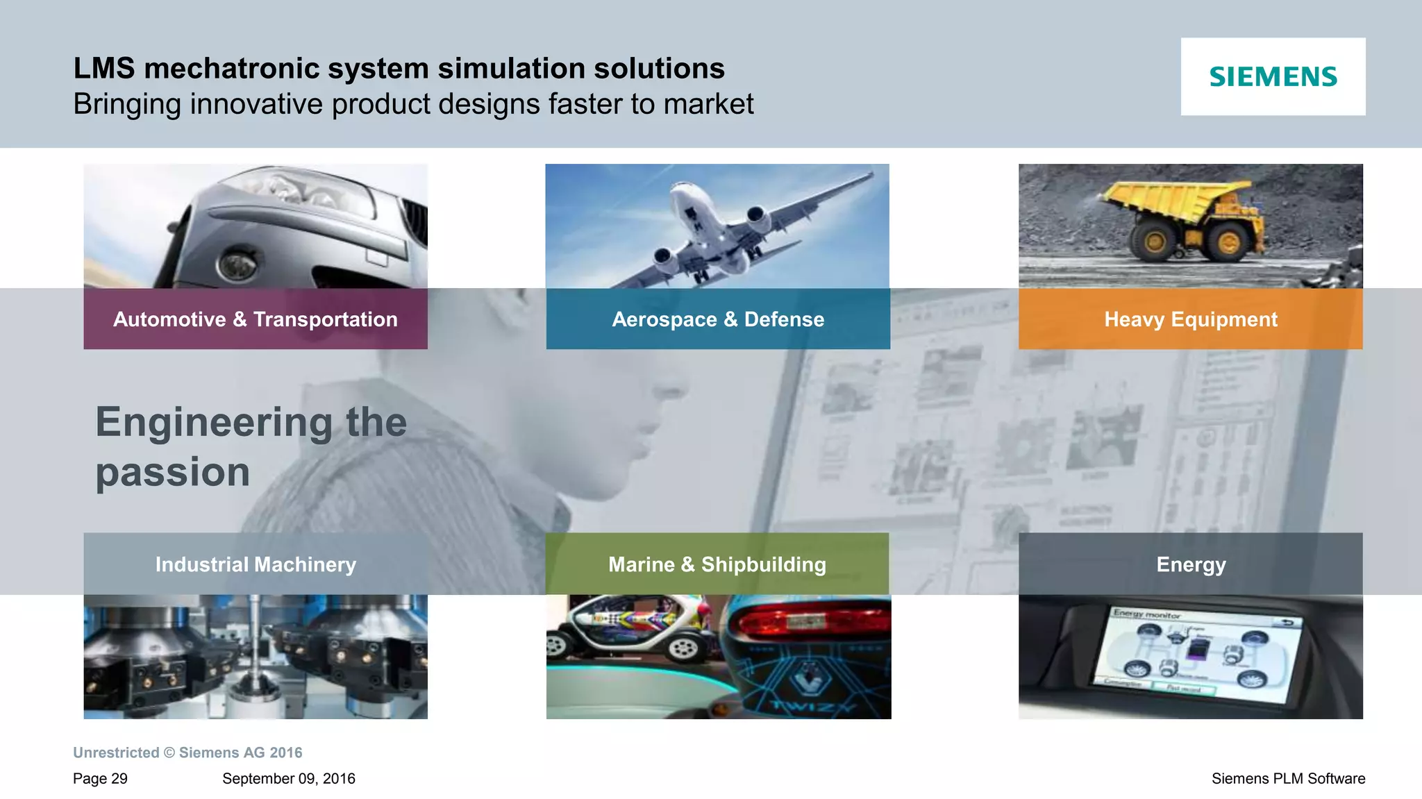
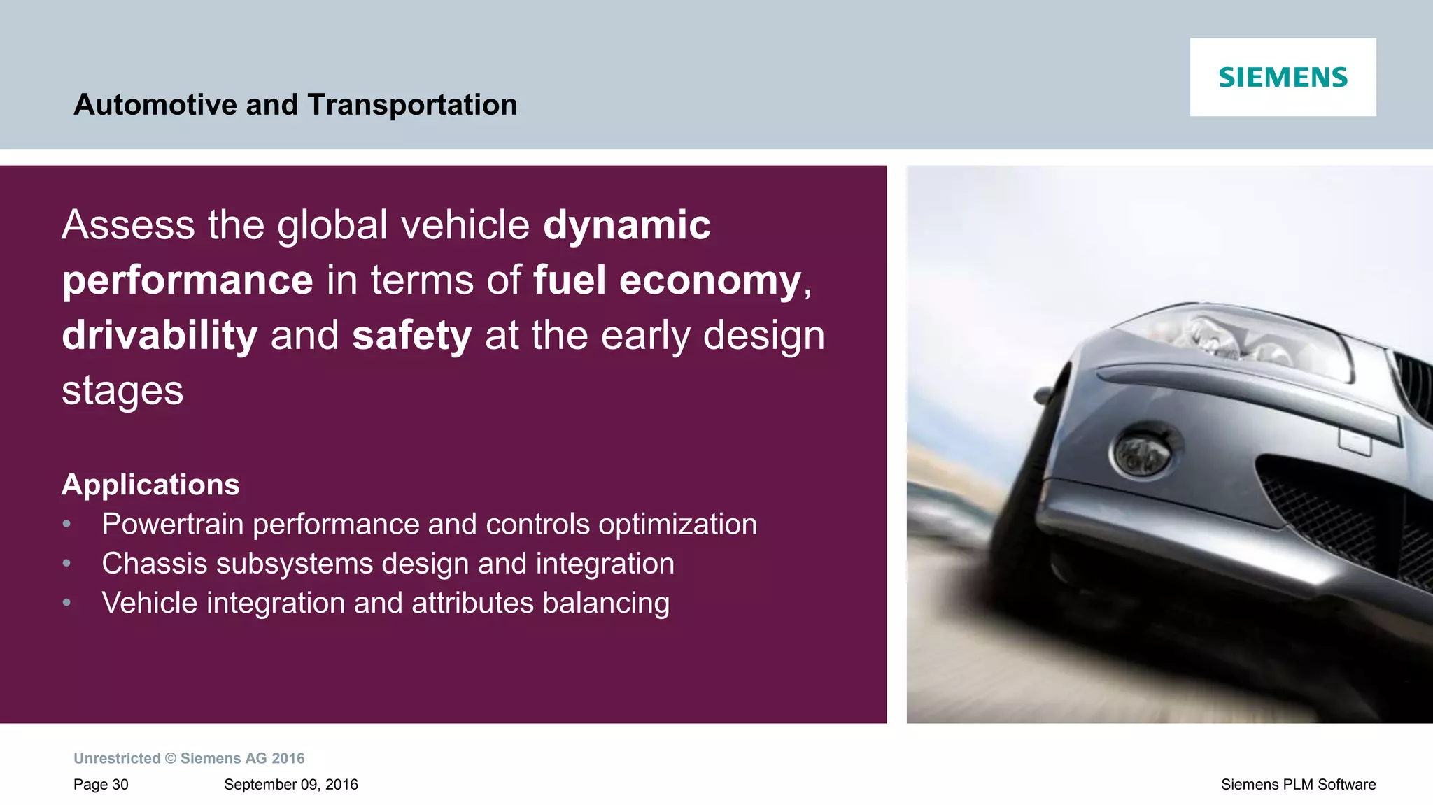
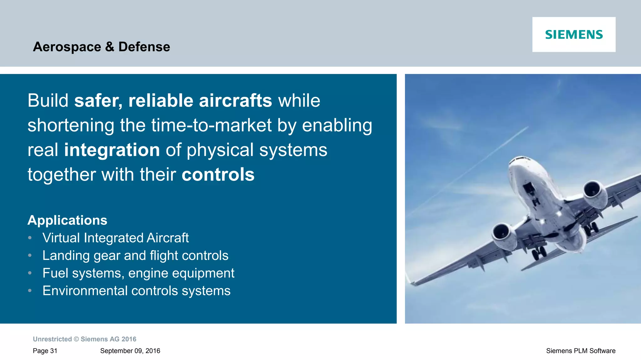
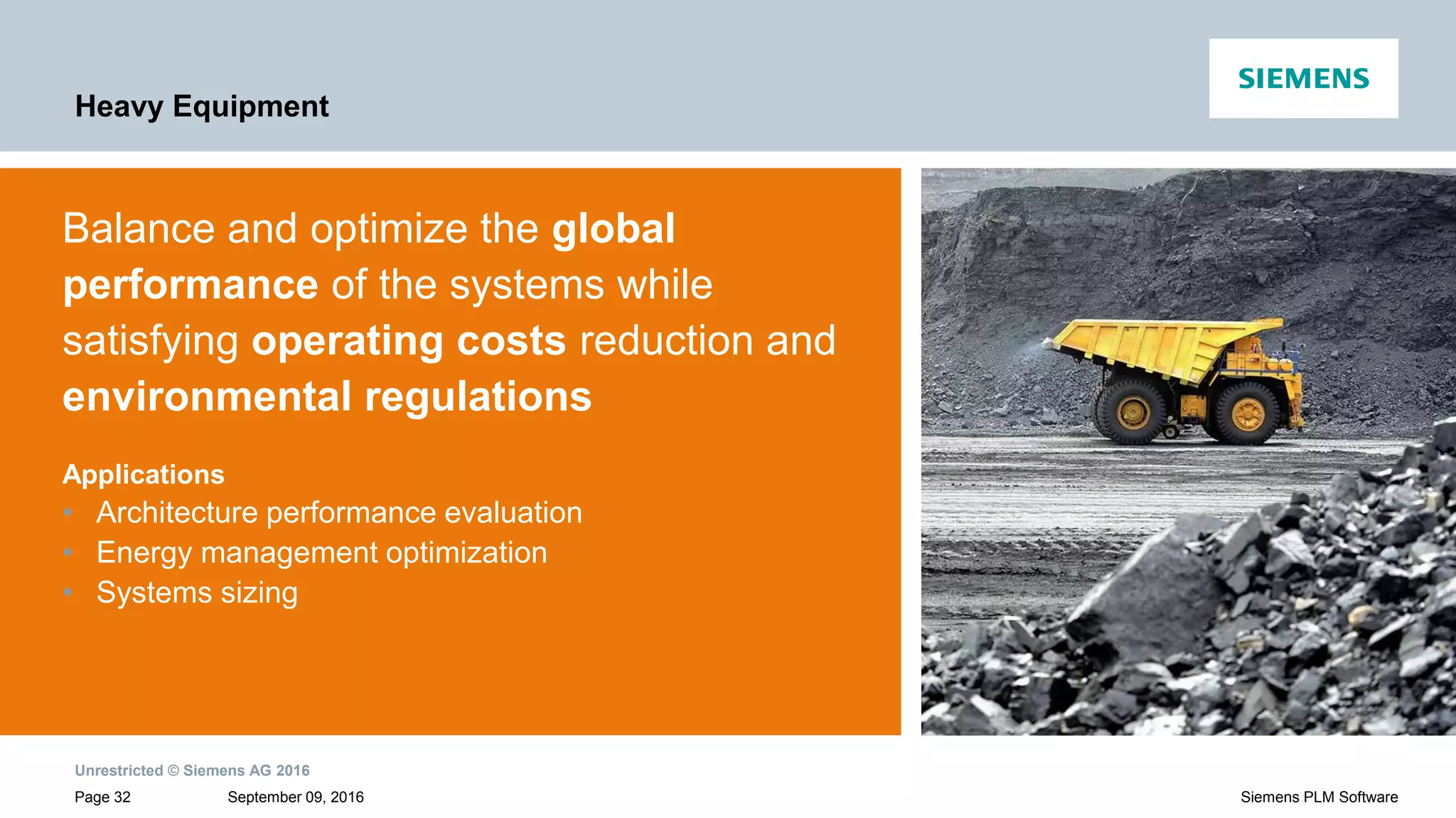
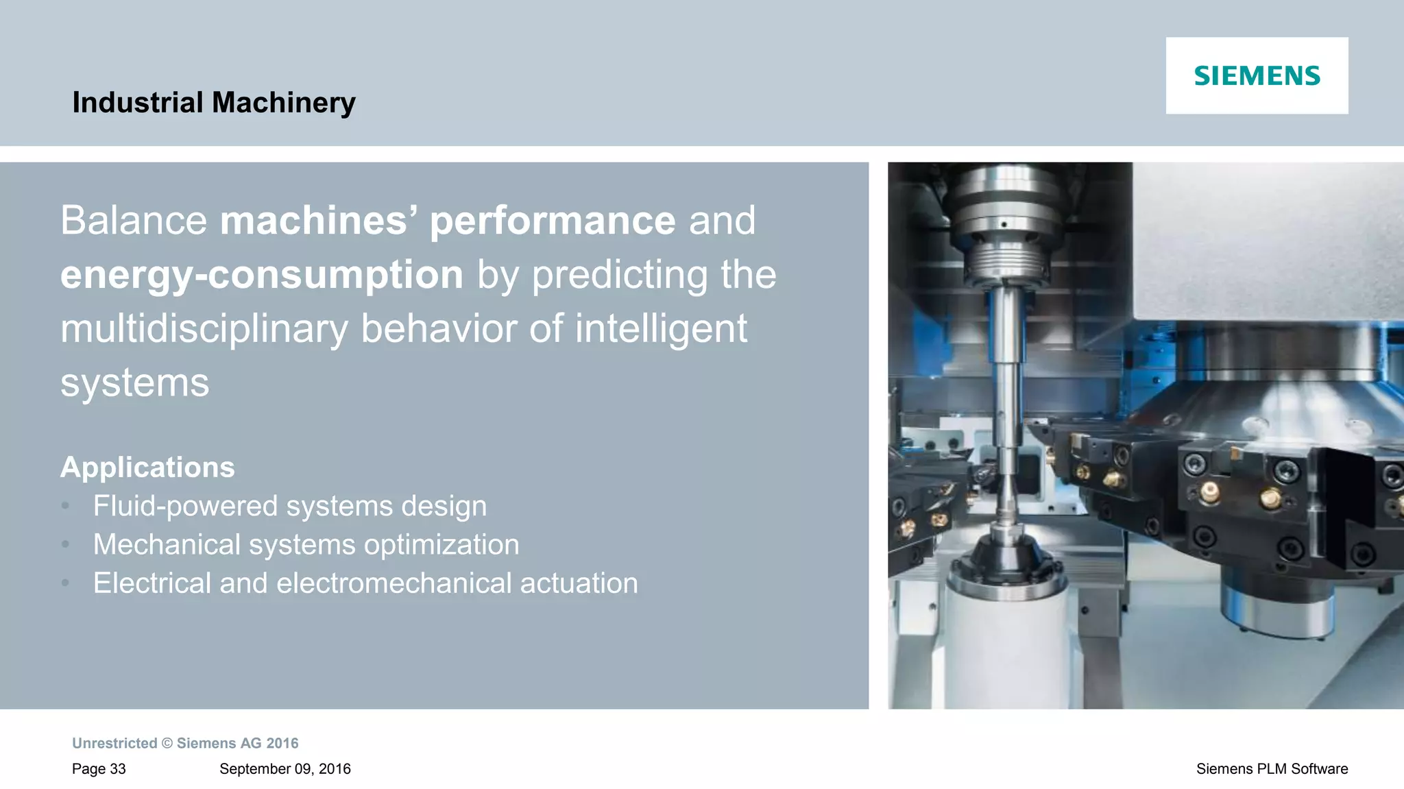
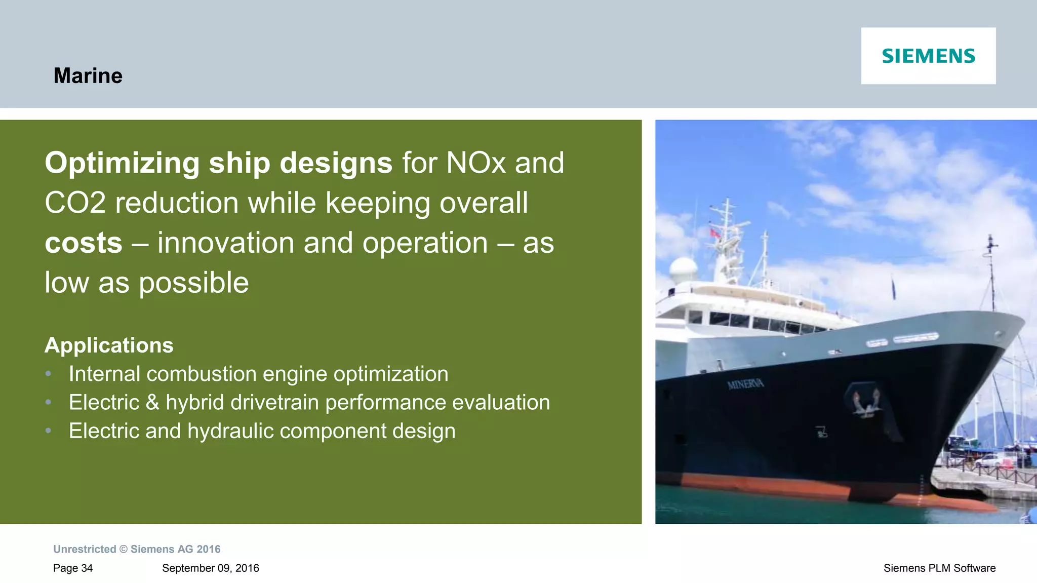
Details applications of mechatronic system simulation in various industries: Automotive, Aerospace, Heavy Equipment, Industrial Machinery, and Marine.
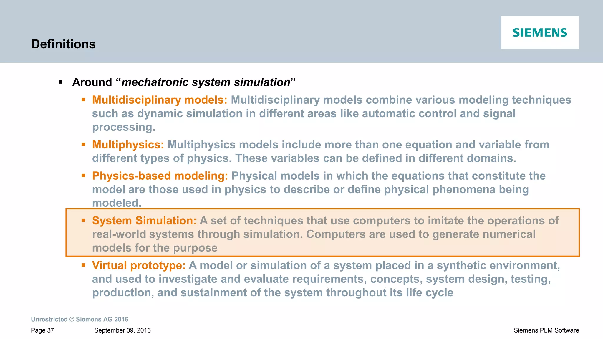
Defines key concepts related to mechatronic system simulation including CAE, mechatronics, multiphysics, and virtual prototypes.
Provides contact details for LMS Amesim representatives at Siemens.