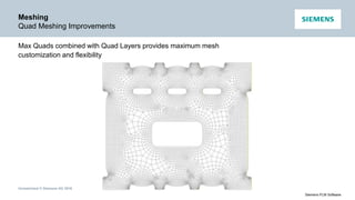
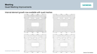
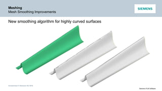
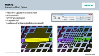
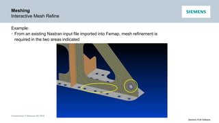
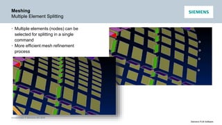
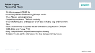
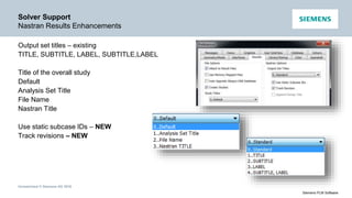
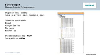
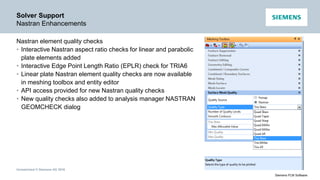
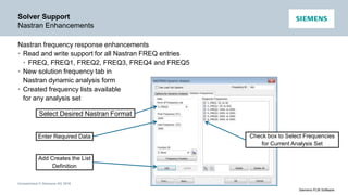
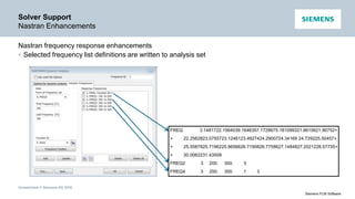
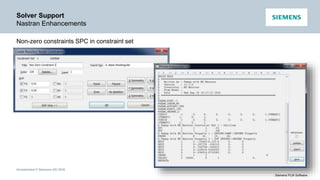
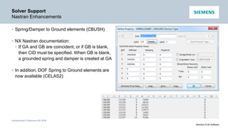
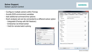
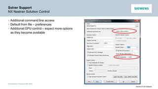
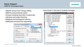
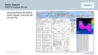
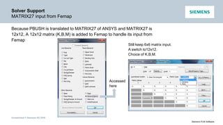
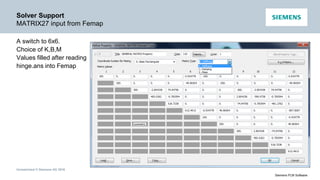
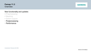
Femap 11.3 What’s New
Unrestricted © Siemens AG 2016
Siemens PLM Software
Femap Release Schedule
Regular release schedule
• v11.3 March 2016
• v11.2 March 2015
• v11.1 November 2013
• v11: January 2013
• v10.3.1: January 2012
• v10.3: October 2011
• v10.2: October 2010
• v10.1.1: January 2010
• v10.1: August 2009
• v10: December 2008
Unrestricted © Siemens AG 2016
Siemens PLM Software
Femap Direction
• A modeling environment that’s dedicated to FEA
• The in-depth, detailed functionality required to accurately model
real-world parts and assemblies
• Customer driven features and functionality
Unrestricted © Siemens AG 2016
Siemens PLM Software
Femap 11.3
Overview
New functionality and updates
• Preprocessing
• Meshing
• Solver support
• Postprocessing
• Performance
Unrestricted © Siemens AG 2016
Siemens PLM Software
Preprocessing
Draw/Erase Toolbar
• New toolbar for draw/erase
• Fast access to mesh and geometry on/off
• Choose entities to draw or erase
• Toggle back and forth
• Choose by element, property, material
• Grow/shrink selection
• Mesh only, geometry only, or linked
• Create Femap group from draw/erase data
• Load Femap group into draw/erase data
Unrestricted © Siemens AG 2016
Siemens PLM Software
Preprocessing
New View Rotation Options
• Default option still “Rotate about View Center”
• Similar to v11.2.x – first two items toggle between view center
and rotation center
• New option – choose between rotating about the “view axes”
(screen) or the “model axes” (global csys)
• New option – “Rotate about Coordinate System” – simply pick
a Femap csys
• “Rotate around vector” same as v11.2.x “rotate around
rotation axis”
Femap v11.2.x
Unrestricted © Siemens AG 2016
Siemens PLM Software
Preprocessing
Rotate Around Cursor
• Accessed via File / Preferences / User
Interface OR add a toolbar icon
• Model rotates about the closest entity on
screen
• Model never swings out of view!
Pick Here
Unrestricted © Siemens AG 2016
Siemens PLM Software
Preprocessing
Zoom Around Cursor
Accessed via File / Preferences / User Interface OR add a toolbar icon
Zoom Here
Unrestricted © Siemens AG 2016
Siemens PLM Software
Preprocessing
Roll Through Mode
• Roll-Thru: move “inside” the model
With Roll-Thru off (and in all previous versions of
Femap) you cannot move through your model, you
just zoom closer and closer
• Roll-Thru moves the viewer’s eye to a certain
depth in the screen direction, everything behind
that is clipped
• Zoom in enough and you’re
inside, and can turn around
and see what was behind you
Unrestricted © Siemens AG 2016
Siemens PLM Software
Preprocessing
Touch Gestures
Graphics Window Gesture Action
One finger drag Dynamic model rotate
Two finger drag Dynamic model pan
Two finger pinch Zoom out
Two finger spread Zoom in
Move one finger around another Rotate around screen z-axis
Touch gestures are available in Graphics and Messages Windows, Entity Editor, Meshing and
Postprocessing Toolboxes, Data Table, Connection Editor, Model Info Tree and Status Bar
Unrestricted © Siemens AG 2016
Siemens PLM Software
Preprocessing
Connection Manager
• New connection editor
• Easier management and access to connections
• Direct editing
• Sorting
• Filters
Unrestricted © Siemens AG 2016
Siemens PLM Software
Preprocessing
Streamlined Element Face Picking
• Face picking automatically loads currently displayed
elements as possible entities to pick from
• Adjacent faces is now the default
• With front picking turned on, only front faces can be
selected, so any face based selection can be made
with a single double-click
Unrestricted © Siemens AG 2016
Siemens PLM Software
Preprocessing
Streamlined Element Face Picking
• Combined with the Draw/Erase toolbar, connection
setup for mesh only parts is much easier and faster
• Workflow:
• With the front picking option turned on
• Choose draw on the Draw/Erase toolbar, and
select the Element option, then pick one element
on each leg
• In the selection box, choose Add All Connected
Elements
• Click OK
Unrestricted © Siemens AG 2016
Siemens PLM Software
Preprocessing
Streamlined Element Face Picking
• Workflow (continued)
• Go to Connect / Connection Region, choose elements,
select the Add Multiple button
• The visible elements are already loaded, pick one on the
end and click OK
• All the connected faces are picked automatically, repeat
each time for the ends
• In just a couple of clicks, six connection regions are
created
Unrestricted © Siemens AG 2016
Siemens PLM Software
Preprocessing
Streamlined Element Face Picking
Workflow (continued)
• While still in the Connect / Connection Region command,
you can use the Draw/Erase toolbar to swap the drawn
entities to pick the other side of the connection
Unrestricted © Siemens AG 2016
Siemens PLM Software
Preprocessing
Beam Modeling Enhancements
Cross section input help
Unrestricted © Siemens AG 2016
Siemens PLM Software
Preprocessing
Beam Modeling Enhancements
Immediate feedback of basic
cross section information
Unrestricted © Siemens AG 2016
Siemens PLM Software
Preprocessing
Beam Modeling Enhancements
Press the “Compute All
Properties” button for full
calculations
Shear center
Unrestricted © Siemens AG 2016
Siemens PLM Software
Preprocessing
Beam Modeling Enhancements
Send report to
clipboard
Save report to BMP,
JPEG, PNG, GIF,
TIFF
Unrestricted © Siemens AG 2016
Siemens PLM Software
Preprocessing
Beam Modeling Enhancements
Nastran shapes
Custom shapes
Unrestricted © Siemens AG 2016
Siemens PLM Software
Preprocessing
Pick Visible
New method for front picking
• Turn on/off in File / Preferences / Graphics
• Much faster than database access
• Uses OpenGL (basic and performance)
to keep track of which ID is front
• If an entity is not represented by a pixel,
it will not be picked, i.e. blocked by
something else, or so small it did not
make a single pixel
• Works in single pick, box, circle,
polygon, etc.
Unrestricted © Siemens AG 2016
Siemens PLM Software
Preprocessing
Unique Property Icons
Unique property icons for properties
Unrestricted © Siemens AG 2016
Siemens PLM Software
Preprocessing
Intelligent Entity Availability
• Only Properties which are appropriate for current Element type are available
• Only Connection Regions are available when creating a Connector
Unrestricted © Siemens AG 2016
Siemens PLM Software
Preprocessing
Renumber All
Renumber all
Unrestricted © Siemens AG 2016
Siemens PLM Software
Preprocessing
API Program File Libraries
• Custom Tools
• Library of API programs delivered with the software
• User Tools
• Reference for your own corporate-wide API program library
Unrestricted © Siemens AG 2016
Siemens PLM Software
Preprocessing
Miscellaneous
• Plane to Plane method now available when using commands on the Modify,
Align… menu. Similar to Between Coordinate Systems method, with
specified plane defining X and Y axes, plane normal defining Z axis.
• Loads
• Added ability to modify the color, modify the layer, scale the values,
change the function ID, or delete loads of specified type(s) in the active
Load Set, All Load Sets, or any number of selected Load Sets.
• Updated Modify, Update Other, Load Phase and Delete, Model, Load -
Body commands to allow selection of any number of Load Sets.
• Constraints
• Added ability to modify the color, modify the layer, or delete constraints of
specified type(s) in the active Constraint Set, all Constraint Sets, or any
number of selected Constraint Sets.
Unrestricted © Siemens AG 2016
Siemens PLM Software
Femap 11.3
Overview
New functionality and updates
• Preprocessing
• Meshing
• Solver support
• Postprocessing
• Performance
Unrestricted © Siemens AG 2016
Siemens PLM Software
Meshing
Quad Meshing Improvements
• Max Quads
• Goal: all quad mesh through triangle removal
• Will allow triangles when required
• With an odd number of edges there will always be one triangle
• Example: default mesh contains 39 triangles – with Max Quads it’s just 1
Default mesh Max Quads mesh
Unrestricted © Siemens AG 2016
Siemens PLM Software
Meshing
Quad Meshing Improvements
• Max Quads
• Mesh size changed by 1 – all triangles removed!
Unrestricted © Siemens AG 2016
Siemens PLM Software
Meshing
Quad Meshing Improvements
Max Quads combined with Quad Layers provides maximum mesh
customization and flexibility
Unrestricted © Siemens AG 2016
Siemens PLM Software
Meshing
Quad Meshing Improvements
Internal element growth now available with quad meshes
Unrestricted © Siemens AG 2016
Siemens PLM Software
Meshing
Mesh Smoothing Improvements
New smoothing algorithm for highly curved surfaces
Unrestricted © Siemens AG 2016
Siemens PLM Software
Meshing
Interactive Mesh Refine
• Interactive update of shell/line mesh
• Auto transition
• Shrink/grow selection
• Drag selection
• Loads/constraints propagated automatically
Unrestricted © Siemens AG 2016
Siemens PLM Software
Meshing
Interactive Mesh Refine
Example:
• From an existing Nastran input file imported into Femap, mesh refinement is
required in the two areas indicated
Unrestricted © Siemens AG 2016
Siemens PLM Software
Meshing
Interactive Mesh Refine
Example (continued)
• At the T junction use Split Edges option
• Choose Edges
• Grow
• Done
Unrestricted © Siemens AG 2016
Siemens PLM Software
Meshing
Interactive Mesh Refine
Example (continued)
• At the hole, refine using Split Edges twice
Unrestricted © Siemens AG 2016
Siemens PLM Software
Meshing
Interactive Mesh Refine
Example (continued)
Unrestricted © Siemens AG 2016
Siemens PLM Software
Meshing
Multiple Element Splitting
• Multiple elements (nodes) can be
selected for splitting in a single
command
• More efficient mesh refinement
process
Unrestricted © Siemens AG 2016
Siemens PLM Software
Meshing
Hard Point Auto Update – Meshing Toolbox
Mesh hard point auto-update within meshing
toolbox
Meshing toolbox commands that update
surfaces will now automatically manage
moving mesh hard points to any split
surfaces
Unrestricted © Siemens AG 2016
Siemens PLM Software
Meshing
Geometry Cleanup – Meshing Toolbox
Small curves and extraneous points are
captured in the mesh
New feature removal tools to permanently
remove them
Similar to composite curves and composite
surfaces, but done at a geometric (Parasolid)
level
Unrestricted © Siemens AG 2016
Siemens PLM Software
Femap 11.3
Overview
New functionality and updates
• Preprocessing
• Meshing
• Solver support
• Postprocessing
• Performance
Unrestricted © Siemens AG 2016
Siemens PLM Software
Solver Support
Abaqus ODB Attach
• First time support of ODB file
• Attach to (instead of internalizing) Abaqus results
• Uses Abaqus scripting interface
• Supports prior version ODB automatically
• Supports field output and recovery of job data including step and increment
files
• Works like currently supported results formats including Nastran OP2 and
XDB, CSV, and Femap FNO
• Fully compatible with all postprocessing functionality
• Selected results can be internalized for data management purposes
Unrestricted © Siemens AG 2016
Siemens PLM Software
Solver Support
Nastran Results Enhancements
Output set titles – existing
TITLE, SUBTITLE, LABEL, SUBTITLE,LABEL
Title of the overall study
Default
Analysis Set Title
File Name
Nastran Title
Use static subcase IDs – NEW
Track revisions – NEW
Unrestricted © Siemens AG 2016
Siemens PLM Software
Solver Support
Nastran Results Enhancements
Output set titles – existing
TITLE, SUBTITLE, LABEL, SUBTITLE,LABEL
Title of the overall study
Default
Analysis Set Title
File Name
Nastran Title
Use static subcase IDs – NEW
Track revisions – NEW
Unrestricted © Siemens AG 2016
Siemens PLM Software
Solver Support
Nastran Enhancements
Nastran element quality checks
• Interactive Nastran aspect ratio checks for linear and parabolic
plate elements added
• Interactive Edge Point Length Ratio (EPLR) check for TRIA6
• Linear plate Nastran element quality checks are now available
in meshing toolbox and entity editor
• API access provided for new Nastran quality checks
• New quality checks also added to analysis manager NASTRAN
GEOMCHECK dialog
Unrestricted © Siemens AG 2016
Siemens PLM Software
Solver Support
Nastran Enhancements
Nastran frequency response enhancements
• Read and write support for all Nastran FREQ entries
• FREQ, FREQ1, FREQ2, FREQ3, FREQ4 and FREQ5
• New solution frequency tab in
Nastran dynamic analysis form
• Created frequency lists available
for any analysis set
Select Desired Nastran Format
Enter Required Data
Add Creates the List
Definition
Check box to Select Frequencies
for Current Analysis Set
Unrestricted © Siemens AG 2016
Siemens PLM Software
Solver Support
Nastran Enhancements
Nastran frequency response enhancements
• Selected frequency list definitions are written to analysis set
FREQ 3.1481722.1564039.1646357.1728675.181099321.8610621.90752+
+ 22.2562823.0755723.1246123.4927424.2900724.34169 24.729225.50457+
+ 25.5587825.7196225.9656626.7190826.7758627.1484827.2021228.57735+
+ 30.0062231.43509
FREQ2 3 200. 300. 5
FREQ4 3 200. 300. .1 3
Unrestricted © Siemens AG 2016
Siemens PLM Software
Solver Support
Nastran Enhancements
Non-zero constraints SPC in constraint set
Unrestricted © Siemens AG 2016
Siemens PLM Software
Solver Support
Nastran Enhancements
• Spring/Damper to Ground elements (CBUSH)
• NX Nastran documentation:
• If GA and GB are coincident, or if GB is blank,
then CID must be specified. When GB is blank,
a grounded spring and damper is created at GA
• In addition, DOF Spring to Ground elements are
now available (CELAS2)
Unrestricted © Siemens AG 2016
Siemens PLM Software
Solver Support
Solver Launch Control
• Configure multiple solvers within Femap
• Avoids DOS environment variables
• Add additional command line options
• Each analysis set can be connected to a different solver option
• Integrated (Femap with NX Nastran)
• Enterprise via linked solver
• VisQ for remote batch solving
Unrestricted © Siemens AG 2016
Siemens PLM Software
Solver Support
NX Nastran Solution Control
• Additional command line access
• Default from file – preferences
• Additional GPU control – expect more options
as they become available
Unrestricted © Siemens AG 2016
Siemens PLM Software
Solver Support
ANSYS Command Input
• ANSYS version from Femap setting
• ANSYS product license option
• Choose including input text in output text
• Jobname and output directory
• Database and workspace memory
• Additional command line arguments
Input shown in the tree of analysis manager
Unrestricted © Siemens AG 2016
Siemens PLM Software
Solver Support
ANSYS Analysis Monitor
• Same look/feel as NX Nastran
• Switch between output text file
and error file
Unrestricted © Siemens AG 2016
Siemens PLM Software
Solver Support
LS-DYNA Translator
• Added support for non-zero constraints
• Added remaining fields for MAT_54 and will now accept
CRIT=0
• Suppress automatic output of *CONTROL_SOLUTION
card
• Limit number of coordinate system translation
messages via max repeated errors field of preferences’
messages tab
• From analysis manager, provide ability to define fields of
*CONTROL_IMPLICIT_AUTO and
*CONTROL_IMPLICIT_GENERAL
• Contact card comments now contain connector and
property titles
Unrestricted © Siemens AG 2016
Siemens PLM Software
Solver Support
ANSYS & Abaqus CBUSH/PBUSH Input
• General Issue: ANSYS and Abaqus do not have an element which exactly
matches the (CBUSH/PBUSH in Nastran) Spring/Damper element in Femap
• Additional Requirement: Spring/Damper elements must behave like
CBUSH/PBUSH when solved with ANSYS or Abaqus, otherwise different
results are calculated
• Possible Solution: Simply include stiffness and damping of Spring/Damper
elements when creating input files for ANSYS or Abaqus
• Our Solution: Spring/Damper elements are written as MATRIX27 elements
for ANSYS; written as *MATRIX INPUT for Abaqus; with matrix values
(stiffness and/or damping) calculated using the same approach as
CBUSH/PBUSH
• Limitation: nonlinearity and frequency dependency are ignored, as the matrix
entries are calculated only once
Unrestricted © Siemens AG 2016
Siemens PLM Software
Solver Support
ANSYS & Abaqus CBUSH/PBUSH Input
BK
Unrestricted © Siemens AG 2016
Siemens PLM Software
Solver Support
ANSYS & Abaqus CBUSH/PBUSH Input
• Element Stiffness:
ET,3,MATRIX27,0,0,4 !kopt1=0, positive definite/semi-positive
!kop2=0, symmetrical
!kop3=4, stiffness
ANSYS element type number, incremented automatically in Femap
• Element Stiffness Matrix:




















78
7776
3324
231413
12321
m
y
s 



R,3 !3=real constants number
RMODIF,3,1,K(1,1) !K11 @ 1
RMODIF,3,2,K(1,2) !K12 @ 2
RMODIF,3,3,K(1,3) !K13 @ 3
…
RMODIF,3,12,K(1,12) !K(1,12) @12
…
RMODIF,3,78,K(12,12) !K(12,12) @78
Unrestricted © Siemens AG 2016
Siemens PLM Software
Solver Support
ANSYS & Abaqus CBUSH/PBUSH Input
• Element Damping:
ET,3,MATRIX27,0,0,4 !kopt1=0, positive definite/semi-positive
!kop2=0, symmetrical
!kop3=5, damping
ANSYS element type number, incremented automatically in Femap
• Element Damping Matrix:




















78
7776
3324
231413
12321
m
y
s 



R,4 !4=real constants number
RMODIF,4,1,K(1,1) !B11 @ 1
RMODIF,4,2,K(1,2) !B12 @ 2
RMODIF,4,3,K(1,3) !B13 @ 3
…
RMODIF,4,12,K(1,12) !B(1,12) @12
…
RMODIF,4,78,K(12,12) !B(12,12) @78
Unrestricted © Siemens AG 2016
Siemens PLM Software
Solver Support
ANSYS & Abaqus CBUSH/PBUSH Input
One CBUSH element verification
Set 1: NX Nastran Set 2: ANSYS Set 3: Abaqus
Results are same
Unrestricted © Siemens AG 2016
Siemens PLM Software
Solver Support
ANSYS CBUSH/PBUSH Input
Transient analysis of a hinge verification
ANSYS stress
NX Nastran stress
Unrestricted © Siemens AG 2016
Siemens PLM Software
Solver Support
CBUSH Translation Notes
• For ANSYS:
 PBUSH to MATRIX27. K and B to two elements, one for K, another for B.
 SPRING/DAMPER to COMBI14.
 “To Ground”: creating a dummy node and apply “D,dummyNode,ALL,ALL”.
• For Abaqus:
 PBUSH to *MATRIX INPUT,… *MATRIX ASSEMBLE. K and B, two matrices.
 Spring (K input) to SPRING2/A, Damper (B input) to DASHPOT2/A.
 PBUSH to Ground, only top-left quarter (11) sub-matrix is written.
 SPRING to Ground (K input) to SPRING1.
 Damper to Ground (B input) to DASHPOT1.
 *MATRIX INPUT,… *MATRIX ASSEMBLE not applicable to analysis other than statics/mode, for other analysis,
CBUSH is not translated and warning is issued.
Unrestricted © Siemens AG 2016
Siemens PLM Software
Solver Support
MATRIX27 input from Femap
Because PBUSH is translated to MATRIX27 of ANSYS and MATRIX27 is
12x12, A 12x12 matrix (K,B,M) is added to Femap to handle its input from
Femap
Accessed
here
Still keep 6x6 matrix input.
A switch to12x12.
Choice of K,B,M.
Unrestricted © Siemens AG 2016
Siemens PLM Software
Solver Support
MATRIX27 input from Femap
A switch to 6x6.
Choice of K,B,M
Values filled after reading
hinge.ans into Femap
Unrestricted © Siemens AG 2016
Siemens PLM Software
Solver Support
Nonzero constraints in ANSYS
• Nonzero constraints were added in Femap 11.3
• Nonzero constraints are easily added to ANSYS as follows
• D,nodeID,dofID,value
• “D,nodeID,dofID,value” are read into Femap 11.3 and stored as a constraint with
nonzero value
Unrestricted © Siemens AG 2016
Siemens PLM Software
Femap 11.3
Overview
New functionality and updates
• Preprocessing
• Meshing
• Solver support
• Postprocessing
• Performance
Unrestricted © Siemens AG 2016
Siemens PLM Software
Postprocessing
Arrow Plots
Contour Vector plots have been completely overhauled for v11.3 and have
been renamed Contour Arrows
Unrestricted © Siemens AG 2016
Siemens PLM Software
Postprocessing
Contour Arrow Plots
Automatic vector selection: the user specifies a single contour vector and
Femap automatically selects appropriate output vectors to display as well as
the correct orientation for relevant elements
Individual output vector selection is still available for advanced users
Unrestricted © Siemens AG 2016
Siemens PLM Software
Postprocessing
Contour Arrow Plots
On-the-fly results transformations: nodal, shell and solid results can now be
displayed in a transformed orientation without having to first manually create a
set of transformed results
Unrestricted © Siemens AG 2016
Siemens PLM Software
Postprocessing
Contour Arrow Plots
Individual component display: display of individual components can be
selectively be turned on and off without having to reselect vectors
Unrestricted © Siemens AG 2016
Siemens PLM Software
Postprocessing
Contour Arrow Plots
Automatic styling: based on the selected output vector, Femap can
automatically select the arrow styles that are the most appropriate for the type
of vector displayed. These settings can always be overridden by the user
Arrow Heads
Arrow Location Arrow Colors
Moment HeadDouble Head Single Head No Head
Arrow at Tail Arrow at Center Contour Colors View Colors
Unrestricted © Siemens AG 2016
Siemens PLM Software
Postprocessing
Contour Arrow Plots
Automatic styling
Plate principals
• Double-headed arrows
• Located at center
Plate membrane
• Single-headed arrows
• Located at tip
• Designed to show
directions for positive
shear flow
Beam axial / shear
• Axial shown with
double-ended arrows at
center
• Shear shown with single
headed arrows at tip
Unrestricted © Siemens AG 2016
Siemens PLM Software
Postprocessing
Contour Arrow Plots
Shear / resultant display: arrows can be shown as individual components,
resultants or selected axial / shear components
Total output vectors (i.e. 1..Total Translation) are
automatically paired with the matching
components and shown as resultants
Component output vectors (i.e. 2..T1
Translation) are automatically paired with the
matching components and shown as individual
components
Unrestricted © Siemens AG 2016
Siemens PLM Software
Postprocessing
Contour Arrow Plots
Shear / resultant display
CBUSH forces in the element coordinate
system shown as individual components
CBUSH forces in the element coordinate
system shown as shear (Y force / Z force) and
axial (X force)
Unrestricted © Siemens AG 2016
Siemens PLM Software
Postprocessing
Contour Arrow Plots
Output listing: when doing automatic vector selection,
List / Output / Contoured Results to Data Table command lists Contour Arrow
results to the data table as they appear on screen
All results remain sortable and entities can be highlighted,
even when resultants or shears are displayed
Unrestricted © Siemens AG 2016
Siemens PLM Software
Postprocessing
Freebodies
Glue and contact: support has been added for glue and contact results as
discrete freebody contributions
For decks created outside Femap, requires
BCTRESULTS or BGRESULTS case control
(automatically included in Femap)
GPFO table still shows an imbalance in the total
nodal summation, so same result can be achieved
by including the reverse of the nodal summation
contribution
Unrestricted © Siemens AG 2016
Siemens PLM Software
Postprocessing
Freebodies
Linear contact model between
hex and tetra mesh, fixed at the
ends. 50# cantilever load applied
to tip of hex mesh
Deformed plot showing linear
contact
Unrestricted © Siemens AG 2016
Siemens PLM Software
Postprocessing
Freebodies
Freebody plot using applied,
SPC, and peripheral element
contributions on nodes and
elements of hex mesh. Applied
load is not balanced
Contact contribution has been
added – summation is now in
equilibrium
Unrestricted © Siemens AG 2016
Siemens PLM Software
Postprocessing
Freebodies
Freebody listing has been rewritten to consolidate commands and add
additional features
v11.2.2
Single Dialog
v11.3
Unrestricted © Siemens AG 2016
Siemens PLM Software
Postprocessing
Freebodies
Freebody listing
• Consolidated into a single dialog box
• Interface loads can be sent directly to the
data table
• Clipboard is a new listing destination option
for tab delimited data
• Listing of F06-style GPFO data has been
streamlined
• Dialog remembers previous settings
Unrestricted © Siemens AG 2016
Siemens PLM Software
Postprocessing
Freebodies
Freebody listing: interface loads in data table
Unrestricted © Siemens AG 2016
Siemens PLM Software
Postprocessing
Freebodies
Freebody listing
• Choosing the clipboard output destination pastes tab delimited data to the
clipboard, similar to what is seen in the data table
• Convenient for pasting to Excel or similar applications
Unrestricted © Siemens AG 2016
Siemens PLM Software
Postprocessing
Freebodies
Freebody listing: F06-style GPFO data
Unrestricted © Siemens AG 2016
Siemens PLM Software
Postprocessing
Freebodies
Default settings: freebody defaults can be set in Preferences / Results tab
Unrestricted © Siemens AG 2016
Siemens PLM Software
Postprocessing
Charting Enhancements
Enhanced support for analysis studies Specify individual studies for Vector vs. Output
Set and Vector vs. Vector data series
Quickly create new data series directly from
the Model Info Tree. Can be added to existing
charts or new ones can be created
Unrestricted © Siemens AG 2016
Siemens PLM Software
Postprocessing
Data Surface Mapping and Miscellaneous
Customer requests
• New APIs to map locations into data surface in same model:
MapOutput:GetOutputDataSurface(ds_id)
MapOutput:MapOutputDataToLocation(count, vXYZ, vValXYZ,
vIsValid)
vIsValid returns 0 if no data map found
• Fixed bug where data surface could become corrupted when using Data
Surface Editor
• Fixed filepath name bugs in Qman
• Validated license server functionality on CentOS v7
Unrestricted © Siemens AG 2016
Siemens PLM Software
Femap 11.3
Overview
New functionality and updates
• Preprocessing
• Meshing
• Solver support
• Postprocessing
• Performance
Unrestricted © Siemens AG 2016
Siemens PLM Software
Performance
Performance Improvements
Addressed specific customer issues:
• Nastran XDB Attach: composite element results – 60x
• Femap sets (API feSet object)
Accessed from your APIs and used internally in Femap are now 30x faster
adding and removing IDs
• Expanding pressure loads on shell elements attached to a surfaces 240x
faster
Unrestricted © Siemens AG 2016
Siemens PLM Software
Performance
Performance Graphics (PG)
• Performance Graphics continues to evolve
• Rigid elements: RBE2, RBE3, and RSPLINE elements are now drawn with
PG, including their DOF labels, independent/dependent symbols and
arrows indicating direction
• Contour Style: arrows are now drawn in PG, together with their numerical
data
• Deformed Style: arrows are now drawn in PG, together with their numerical
data
• Performance Graphics will be temporarily disabled when an unsupported
command is used (i.e., Dynamic Cutting Plane, Dynamic IsoSurface, etc),
then be enabled again after exiting the command
Unrestricted © Siemens AG 2016
Siemens PLM Software
Q and A

Femap 11.3 Whats New Presentation

  • 1.
  • 2.
    Unrestricted © SiemensAG 2016 Siemens PLM Software Femap Release Schedule Regular release schedule • v11.3 March 2016 • v11.2 March 2015 • v11.1 November 2013 • v11: January 2013 • v10.3.1: January 2012 • v10.3: October 2011 • v10.2: October 2010 • v10.1.1: January 2010 • v10.1: August 2009 • v10: December 2008
  • 3.
    Unrestricted © SiemensAG 2016 Siemens PLM Software Femap Direction • A modeling environment that’s dedicated to FEA • The in-depth, detailed functionality required to accurately model real-world parts and assemblies • Customer driven features and functionality
  • 4.
    Unrestricted © SiemensAG 2016 Siemens PLM Software Femap 11.3 Overview New functionality and updates • Preprocessing • Meshing • Solver support • Postprocessing • Performance
  • 5.
    Unrestricted © SiemensAG 2016 Siemens PLM Software Preprocessing Draw/Erase Toolbar • New toolbar for draw/erase • Fast access to mesh and geometry on/off • Choose entities to draw or erase • Toggle back and forth • Choose by element, property, material • Grow/shrink selection • Mesh only, geometry only, or linked • Create Femap group from draw/erase data • Load Femap group into draw/erase data
  • 6.
    Unrestricted © SiemensAG 2016 Siemens PLM Software Preprocessing New View Rotation Options • Default option still “Rotate about View Center” • Similar to v11.2.x – first two items toggle between view center and rotation center • New option – choose between rotating about the “view axes” (screen) or the “model axes” (global csys) • New option – “Rotate about Coordinate System” – simply pick a Femap csys • “Rotate around vector” same as v11.2.x “rotate around rotation axis” Femap v11.2.x
  • 7.
    Unrestricted © SiemensAG 2016 Siemens PLM Software Preprocessing Rotate Around Cursor • Accessed via File / Preferences / User Interface OR add a toolbar icon • Model rotates about the closest entity on screen • Model never swings out of view! Pick Here
  • 8.
    Unrestricted © SiemensAG 2016 Siemens PLM Software Preprocessing Zoom Around Cursor Accessed via File / Preferences / User Interface OR add a toolbar icon Zoom Here
  • 9.
    Unrestricted © SiemensAG 2016 Siemens PLM Software Preprocessing Roll Through Mode • Roll-Thru: move “inside” the model With Roll-Thru off (and in all previous versions of Femap) you cannot move through your model, you just zoom closer and closer • Roll-Thru moves the viewer’s eye to a certain depth in the screen direction, everything behind that is clipped • Zoom in enough and you’re inside, and can turn around and see what was behind you
  • 10.
    Unrestricted © SiemensAG 2016 Siemens PLM Software Preprocessing Touch Gestures Graphics Window Gesture Action One finger drag Dynamic model rotate Two finger drag Dynamic model pan Two finger pinch Zoom out Two finger spread Zoom in Move one finger around another Rotate around screen z-axis Touch gestures are available in Graphics and Messages Windows, Entity Editor, Meshing and Postprocessing Toolboxes, Data Table, Connection Editor, Model Info Tree and Status Bar
  • 11.
    Unrestricted © SiemensAG 2016 Siemens PLM Software Preprocessing Connection Manager • New connection editor • Easier management and access to connections • Direct editing • Sorting • Filters
  • 12.
    Unrestricted © SiemensAG 2016 Siemens PLM Software Preprocessing Streamlined Element Face Picking • Face picking automatically loads currently displayed elements as possible entities to pick from • Adjacent faces is now the default • With front picking turned on, only front faces can be selected, so any face based selection can be made with a single double-click
  • 13.
    Unrestricted © SiemensAG 2016 Siemens PLM Software Preprocessing Streamlined Element Face Picking • Combined with the Draw/Erase toolbar, connection setup for mesh only parts is much easier and faster • Workflow: • With the front picking option turned on • Choose draw on the Draw/Erase toolbar, and select the Element option, then pick one element on each leg • In the selection box, choose Add All Connected Elements • Click OK
  • 14.
    Unrestricted © SiemensAG 2016 Siemens PLM Software Preprocessing Streamlined Element Face Picking • Workflow (continued) • Go to Connect / Connection Region, choose elements, select the Add Multiple button • The visible elements are already loaded, pick one on the end and click OK • All the connected faces are picked automatically, repeat each time for the ends • In just a couple of clicks, six connection regions are created
  • 15.
    Unrestricted © SiemensAG 2016 Siemens PLM Software Preprocessing Streamlined Element Face Picking Workflow (continued) • While still in the Connect / Connection Region command, you can use the Draw/Erase toolbar to swap the drawn entities to pick the other side of the connection
  • 16.
    Unrestricted © SiemensAG 2016 Siemens PLM Software Preprocessing Beam Modeling Enhancements Cross section input help
  • 17.
    Unrestricted © SiemensAG 2016 Siemens PLM Software Preprocessing Beam Modeling Enhancements Immediate feedback of basic cross section information
  • 18.
    Unrestricted © SiemensAG 2016 Siemens PLM Software Preprocessing Beam Modeling Enhancements Press the “Compute All Properties” button for full calculations Shear center
  • 19.
    Unrestricted © SiemensAG 2016 Siemens PLM Software Preprocessing Beam Modeling Enhancements Send report to clipboard Save report to BMP, JPEG, PNG, GIF, TIFF
  • 20.
    Unrestricted © SiemensAG 2016 Siemens PLM Software Preprocessing Beam Modeling Enhancements Nastran shapes Custom shapes
  • 21.
    Unrestricted © SiemensAG 2016 Siemens PLM Software Preprocessing Pick Visible New method for front picking • Turn on/off in File / Preferences / Graphics • Much faster than database access • Uses OpenGL (basic and performance) to keep track of which ID is front • If an entity is not represented by a pixel, it will not be picked, i.e. blocked by something else, or so small it did not make a single pixel • Works in single pick, box, circle, polygon, etc.
  • 22.
    Unrestricted © SiemensAG 2016 Siemens PLM Software Preprocessing Unique Property Icons Unique property icons for properties
  • 23.
    Unrestricted © SiemensAG 2016 Siemens PLM Software Preprocessing Intelligent Entity Availability • Only Properties which are appropriate for current Element type are available • Only Connection Regions are available when creating a Connector
  • 24.
    Unrestricted © SiemensAG 2016 Siemens PLM Software Preprocessing Renumber All Renumber all
  • 25.
    Unrestricted © SiemensAG 2016 Siemens PLM Software Preprocessing API Program File Libraries • Custom Tools • Library of API programs delivered with the software • User Tools • Reference for your own corporate-wide API program library
  • 26.
    Unrestricted © SiemensAG 2016 Siemens PLM Software Preprocessing Miscellaneous • Plane to Plane method now available when using commands on the Modify, Align… menu. Similar to Between Coordinate Systems method, with specified plane defining X and Y axes, plane normal defining Z axis. • Loads • Added ability to modify the color, modify the layer, scale the values, change the function ID, or delete loads of specified type(s) in the active Load Set, All Load Sets, or any number of selected Load Sets. • Updated Modify, Update Other, Load Phase and Delete, Model, Load - Body commands to allow selection of any number of Load Sets. • Constraints • Added ability to modify the color, modify the layer, or delete constraints of specified type(s) in the active Constraint Set, all Constraint Sets, or any number of selected Constraint Sets.
  • 27.
    Unrestricted © SiemensAG 2016 Siemens PLM Software Femap 11.3 Overview New functionality and updates • Preprocessing • Meshing • Solver support • Postprocessing • Performance
  • 28.
    Unrestricted © SiemensAG 2016 Siemens PLM Software Meshing Quad Meshing Improvements • Max Quads • Goal: all quad mesh through triangle removal • Will allow triangles when required • With an odd number of edges there will always be one triangle • Example: default mesh contains 39 triangles – with Max Quads it’s just 1 Default mesh Max Quads mesh
  • 29.
    Unrestricted © SiemensAG 2016 Siemens PLM Software Meshing Quad Meshing Improvements • Max Quads • Mesh size changed by 1 – all triangles removed!
  • 30.
    Unrestricted © SiemensAG 2016 Siemens PLM Software Meshing Quad Meshing Improvements Max Quads combined with Quad Layers provides maximum mesh customization and flexibility
  • 31.
    Unrestricted © SiemensAG 2016 Siemens PLM Software Meshing Quad Meshing Improvements Internal element growth now available with quad meshes
  • 32.
    Unrestricted © SiemensAG 2016 Siemens PLM Software Meshing Mesh Smoothing Improvements New smoothing algorithm for highly curved surfaces
  • 33.
    Unrestricted © SiemensAG 2016 Siemens PLM Software Meshing Interactive Mesh Refine • Interactive update of shell/line mesh • Auto transition • Shrink/grow selection • Drag selection • Loads/constraints propagated automatically
  • 34.
    Unrestricted © SiemensAG 2016 Siemens PLM Software Meshing Interactive Mesh Refine Example: • From an existing Nastran input file imported into Femap, mesh refinement is required in the two areas indicated
  • 35.
    Unrestricted © SiemensAG 2016 Siemens PLM Software Meshing Interactive Mesh Refine Example (continued) • At the T junction use Split Edges option • Choose Edges • Grow • Done
  • 36.
    Unrestricted © SiemensAG 2016 Siemens PLM Software Meshing Interactive Mesh Refine Example (continued) • At the hole, refine using Split Edges twice
  • 37.
    Unrestricted © SiemensAG 2016 Siemens PLM Software Meshing Interactive Mesh Refine Example (continued)
  • 38.
    Unrestricted © SiemensAG 2016 Siemens PLM Software Meshing Multiple Element Splitting • Multiple elements (nodes) can be selected for splitting in a single command • More efficient mesh refinement process
  • 39.
    Unrestricted © SiemensAG 2016 Siemens PLM Software Meshing Hard Point Auto Update – Meshing Toolbox Mesh hard point auto-update within meshing toolbox Meshing toolbox commands that update surfaces will now automatically manage moving mesh hard points to any split surfaces
  • 40.
    Unrestricted © SiemensAG 2016 Siemens PLM Software Meshing Geometry Cleanup – Meshing Toolbox Small curves and extraneous points are captured in the mesh New feature removal tools to permanently remove them Similar to composite curves and composite surfaces, but done at a geometric (Parasolid) level
  • 41.
    Unrestricted © SiemensAG 2016 Siemens PLM Software Femap 11.3 Overview New functionality and updates • Preprocessing • Meshing • Solver support • Postprocessing • Performance
  • 42.
    Unrestricted © SiemensAG 2016 Siemens PLM Software Solver Support Abaqus ODB Attach • First time support of ODB file • Attach to (instead of internalizing) Abaqus results • Uses Abaqus scripting interface • Supports prior version ODB automatically • Supports field output and recovery of job data including step and increment files • Works like currently supported results formats including Nastran OP2 and XDB, CSV, and Femap FNO • Fully compatible with all postprocessing functionality • Selected results can be internalized for data management purposes
  • 43.
    Unrestricted © SiemensAG 2016 Siemens PLM Software Solver Support Nastran Results Enhancements Output set titles – existing TITLE, SUBTITLE, LABEL, SUBTITLE,LABEL Title of the overall study Default Analysis Set Title File Name Nastran Title Use static subcase IDs – NEW Track revisions – NEW
  • 44.
    Unrestricted © SiemensAG 2016 Siemens PLM Software Solver Support Nastran Results Enhancements Output set titles – existing TITLE, SUBTITLE, LABEL, SUBTITLE,LABEL Title of the overall study Default Analysis Set Title File Name Nastran Title Use static subcase IDs – NEW Track revisions – NEW
  • 45.
    Unrestricted © SiemensAG 2016 Siemens PLM Software Solver Support Nastran Enhancements Nastran element quality checks • Interactive Nastran aspect ratio checks for linear and parabolic plate elements added • Interactive Edge Point Length Ratio (EPLR) check for TRIA6 • Linear plate Nastran element quality checks are now available in meshing toolbox and entity editor • API access provided for new Nastran quality checks • New quality checks also added to analysis manager NASTRAN GEOMCHECK dialog
  • 46.
    Unrestricted © SiemensAG 2016 Siemens PLM Software Solver Support Nastran Enhancements Nastran frequency response enhancements • Read and write support for all Nastran FREQ entries • FREQ, FREQ1, FREQ2, FREQ3, FREQ4 and FREQ5 • New solution frequency tab in Nastran dynamic analysis form • Created frequency lists available for any analysis set Select Desired Nastran Format Enter Required Data Add Creates the List Definition Check box to Select Frequencies for Current Analysis Set
  • 47.
    Unrestricted © SiemensAG 2016 Siemens PLM Software Solver Support Nastran Enhancements Nastran frequency response enhancements • Selected frequency list definitions are written to analysis set FREQ 3.1481722.1564039.1646357.1728675.181099321.8610621.90752+ + 22.2562823.0755723.1246123.4927424.2900724.34169 24.729225.50457+ + 25.5587825.7196225.9656626.7190826.7758627.1484827.2021228.57735+ + 30.0062231.43509 FREQ2 3 200. 300. 5 FREQ4 3 200. 300. .1 3
  • 48.
    Unrestricted © SiemensAG 2016 Siemens PLM Software Solver Support Nastran Enhancements Non-zero constraints SPC in constraint set
  • 49.
    Unrestricted © SiemensAG 2016 Siemens PLM Software Solver Support Nastran Enhancements • Spring/Damper to Ground elements (CBUSH) • NX Nastran documentation: • If GA and GB are coincident, or if GB is blank, then CID must be specified. When GB is blank, a grounded spring and damper is created at GA • In addition, DOF Spring to Ground elements are now available (CELAS2)
  • 50.
    Unrestricted © SiemensAG 2016 Siemens PLM Software Solver Support Solver Launch Control • Configure multiple solvers within Femap • Avoids DOS environment variables • Add additional command line options • Each analysis set can be connected to a different solver option • Integrated (Femap with NX Nastran) • Enterprise via linked solver • VisQ for remote batch solving
  • 51.
    Unrestricted © SiemensAG 2016 Siemens PLM Software Solver Support NX Nastran Solution Control • Additional command line access • Default from file – preferences • Additional GPU control – expect more options as they become available
  • 52.
    Unrestricted © SiemensAG 2016 Siemens PLM Software Solver Support ANSYS Command Input • ANSYS version from Femap setting • ANSYS product license option • Choose including input text in output text • Jobname and output directory • Database and workspace memory • Additional command line arguments Input shown in the tree of analysis manager
  • 53.
    Unrestricted © SiemensAG 2016 Siemens PLM Software Solver Support ANSYS Analysis Monitor • Same look/feel as NX Nastran • Switch between output text file and error file
  • 54.
    Unrestricted © SiemensAG 2016 Siemens PLM Software Solver Support LS-DYNA Translator • Added support for non-zero constraints • Added remaining fields for MAT_54 and will now accept CRIT=0 • Suppress automatic output of *CONTROL_SOLUTION card • Limit number of coordinate system translation messages via max repeated errors field of preferences’ messages tab • From analysis manager, provide ability to define fields of *CONTROL_IMPLICIT_AUTO and *CONTROL_IMPLICIT_GENERAL • Contact card comments now contain connector and property titles
  • 55.
    Unrestricted © SiemensAG 2016 Siemens PLM Software Solver Support ANSYS & Abaqus CBUSH/PBUSH Input • General Issue: ANSYS and Abaqus do not have an element which exactly matches the (CBUSH/PBUSH in Nastran) Spring/Damper element in Femap • Additional Requirement: Spring/Damper elements must behave like CBUSH/PBUSH when solved with ANSYS or Abaqus, otherwise different results are calculated • Possible Solution: Simply include stiffness and damping of Spring/Damper elements when creating input files for ANSYS or Abaqus • Our Solution: Spring/Damper elements are written as MATRIX27 elements for ANSYS; written as *MATRIX INPUT for Abaqus; with matrix values (stiffness and/or damping) calculated using the same approach as CBUSH/PBUSH • Limitation: nonlinearity and frequency dependency are ignored, as the matrix entries are calculated only once
  • 56.
    Unrestricted © SiemensAG 2016 Siemens PLM Software Solver Support ANSYS & Abaqus CBUSH/PBUSH Input BK
  • 57.
    Unrestricted © SiemensAG 2016 Siemens PLM Software Solver Support ANSYS & Abaqus CBUSH/PBUSH Input • Element Stiffness: ET,3,MATRIX27,0,0,4 !kopt1=0, positive definite/semi-positive !kop2=0, symmetrical !kop3=4, stiffness ANSYS element type number, incremented automatically in Femap • Element Stiffness Matrix:                     78 7776 3324 231413 12321 m y s     R,3 !3=real constants number RMODIF,3,1,K(1,1) !K11 @ 1 RMODIF,3,2,K(1,2) !K12 @ 2 RMODIF,3,3,K(1,3) !K13 @ 3 … RMODIF,3,12,K(1,12) !K(1,12) @12 … RMODIF,3,78,K(12,12) !K(12,12) @78
  • 58.
    Unrestricted © SiemensAG 2016 Siemens PLM Software Solver Support ANSYS & Abaqus CBUSH/PBUSH Input • Element Damping: ET,3,MATRIX27,0,0,4 !kopt1=0, positive definite/semi-positive !kop2=0, symmetrical !kop3=5, damping ANSYS element type number, incremented automatically in Femap • Element Damping Matrix:                     78 7776 3324 231413 12321 m y s     R,4 !4=real constants number RMODIF,4,1,K(1,1) !B11 @ 1 RMODIF,4,2,K(1,2) !B12 @ 2 RMODIF,4,3,K(1,3) !B13 @ 3 … RMODIF,4,12,K(1,12) !B(1,12) @12 … RMODIF,4,78,K(12,12) !B(12,12) @78
  • 59.
    Unrestricted © SiemensAG 2016 Siemens PLM Software Solver Support ANSYS & Abaqus CBUSH/PBUSH Input One CBUSH element verification Set 1: NX Nastran Set 2: ANSYS Set 3: Abaqus Results are same
  • 60.
    Unrestricted © SiemensAG 2016 Siemens PLM Software Solver Support ANSYS CBUSH/PBUSH Input Transient analysis of a hinge verification ANSYS stress NX Nastran stress
  • 61.
    Unrestricted © SiemensAG 2016 Siemens PLM Software Solver Support CBUSH Translation Notes • For ANSYS:  PBUSH to MATRIX27. K and B to two elements, one for K, another for B.  SPRING/DAMPER to COMBI14.  “To Ground”: creating a dummy node and apply “D,dummyNode,ALL,ALL”. • For Abaqus:  PBUSH to *MATRIX INPUT,… *MATRIX ASSEMBLE. K and B, two matrices.  Spring (K input) to SPRING2/A, Damper (B input) to DASHPOT2/A.  PBUSH to Ground, only top-left quarter (11) sub-matrix is written.  SPRING to Ground (K input) to SPRING1.  Damper to Ground (B input) to DASHPOT1.  *MATRIX INPUT,… *MATRIX ASSEMBLE not applicable to analysis other than statics/mode, for other analysis, CBUSH is not translated and warning is issued.
  • 62.
    Unrestricted © SiemensAG 2016 Siemens PLM Software Solver Support MATRIX27 input from Femap Because PBUSH is translated to MATRIX27 of ANSYS and MATRIX27 is 12x12, A 12x12 matrix (K,B,M) is added to Femap to handle its input from Femap Accessed here Still keep 6x6 matrix input. A switch to12x12. Choice of K,B,M.
  • 63.
    Unrestricted © SiemensAG 2016 Siemens PLM Software Solver Support MATRIX27 input from Femap A switch to 6x6. Choice of K,B,M Values filled after reading hinge.ans into Femap
  • 64.
    Unrestricted © SiemensAG 2016 Siemens PLM Software Solver Support Nonzero constraints in ANSYS • Nonzero constraints were added in Femap 11.3 • Nonzero constraints are easily added to ANSYS as follows • D,nodeID,dofID,value • “D,nodeID,dofID,value” are read into Femap 11.3 and stored as a constraint with nonzero value
  • 65.
    Unrestricted © SiemensAG 2016 Siemens PLM Software Femap 11.3 Overview New functionality and updates • Preprocessing • Meshing • Solver support • Postprocessing • Performance
  • 66.
    Unrestricted © SiemensAG 2016 Siemens PLM Software Postprocessing Arrow Plots Contour Vector plots have been completely overhauled for v11.3 and have been renamed Contour Arrows
  • 67.
    Unrestricted © SiemensAG 2016 Siemens PLM Software Postprocessing Contour Arrow Plots Automatic vector selection: the user specifies a single contour vector and Femap automatically selects appropriate output vectors to display as well as the correct orientation for relevant elements Individual output vector selection is still available for advanced users
  • 68.
    Unrestricted © SiemensAG 2016 Siemens PLM Software Postprocessing Contour Arrow Plots On-the-fly results transformations: nodal, shell and solid results can now be displayed in a transformed orientation without having to first manually create a set of transformed results
  • 69.
    Unrestricted © SiemensAG 2016 Siemens PLM Software Postprocessing Contour Arrow Plots Individual component display: display of individual components can be selectively be turned on and off without having to reselect vectors
  • 70.
    Unrestricted © SiemensAG 2016 Siemens PLM Software Postprocessing Contour Arrow Plots Automatic styling: based on the selected output vector, Femap can automatically select the arrow styles that are the most appropriate for the type of vector displayed. These settings can always be overridden by the user Arrow Heads Arrow Location Arrow Colors Moment HeadDouble Head Single Head No Head Arrow at Tail Arrow at Center Contour Colors View Colors
  • 71.
    Unrestricted © SiemensAG 2016 Siemens PLM Software Postprocessing Contour Arrow Plots Automatic styling Plate principals • Double-headed arrows • Located at center Plate membrane • Single-headed arrows • Located at tip • Designed to show directions for positive shear flow Beam axial / shear • Axial shown with double-ended arrows at center • Shear shown with single headed arrows at tip
  • 72.
    Unrestricted © SiemensAG 2016 Siemens PLM Software Postprocessing Contour Arrow Plots Shear / resultant display: arrows can be shown as individual components, resultants or selected axial / shear components Total output vectors (i.e. 1..Total Translation) are automatically paired with the matching components and shown as resultants Component output vectors (i.e. 2..T1 Translation) are automatically paired with the matching components and shown as individual components
  • 73.
    Unrestricted © SiemensAG 2016 Siemens PLM Software Postprocessing Contour Arrow Plots Shear / resultant display CBUSH forces in the element coordinate system shown as individual components CBUSH forces in the element coordinate system shown as shear (Y force / Z force) and axial (X force)
  • 74.
    Unrestricted © SiemensAG 2016 Siemens PLM Software Postprocessing Contour Arrow Plots Output listing: when doing automatic vector selection, List / Output / Contoured Results to Data Table command lists Contour Arrow results to the data table as they appear on screen All results remain sortable and entities can be highlighted, even when resultants or shears are displayed
  • 75.
    Unrestricted © SiemensAG 2016 Siemens PLM Software Postprocessing Freebodies Glue and contact: support has been added for glue and contact results as discrete freebody contributions For decks created outside Femap, requires BCTRESULTS or BGRESULTS case control (automatically included in Femap) GPFO table still shows an imbalance in the total nodal summation, so same result can be achieved by including the reverse of the nodal summation contribution
  • 76.
    Unrestricted © SiemensAG 2016 Siemens PLM Software Postprocessing Freebodies Linear contact model between hex and tetra mesh, fixed at the ends. 50# cantilever load applied to tip of hex mesh Deformed plot showing linear contact
  • 77.
    Unrestricted © SiemensAG 2016 Siemens PLM Software Postprocessing Freebodies Freebody plot using applied, SPC, and peripheral element contributions on nodes and elements of hex mesh. Applied load is not balanced Contact contribution has been added – summation is now in equilibrium
  • 78.
    Unrestricted © SiemensAG 2016 Siemens PLM Software Postprocessing Freebodies Freebody listing has been rewritten to consolidate commands and add additional features v11.2.2 Single Dialog v11.3
  • 79.
    Unrestricted © SiemensAG 2016 Siemens PLM Software Postprocessing Freebodies Freebody listing • Consolidated into a single dialog box • Interface loads can be sent directly to the data table • Clipboard is a new listing destination option for tab delimited data • Listing of F06-style GPFO data has been streamlined • Dialog remembers previous settings
  • 80.
    Unrestricted © SiemensAG 2016 Siemens PLM Software Postprocessing Freebodies Freebody listing: interface loads in data table
  • 81.
    Unrestricted © SiemensAG 2016 Siemens PLM Software Postprocessing Freebodies Freebody listing • Choosing the clipboard output destination pastes tab delimited data to the clipboard, similar to what is seen in the data table • Convenient for pasting to Excel or similar applications
  • 82.
    Unrestricted © SiemensAG 2016 Siemens PLM Software Postprocessing Freebodies Freebody listing: F06-style GPFO data
  • 83.
    Unrestricted © SiemensAG 2016 Siemens PLM Software Postprocessing Freebodies Default settings: freebody defaults can be set in Preferences / Results tab
  • 84.
    Unrestricted © SiemensAG 2016 Siemens PLM Software Postprocessing Charting Enhancements Enhanced support for analysis studies Specify individual studies for Vector vs. Output Set and Vector vs. Vector data series Quickly create new data series directly from the Model Info Tree. Can be added to existing charts or new ones can be created
  • 85.
    Unrestricted © SiemensAG 2016 Siemens PLM Software Postprocessing Data Surface Mapping and Miscellaneous Customer requests • New APIs to map locations into data surface in same model: MapOutput:GetOutputDataSurface(ds_id) MapOutput:MapOutputDataToLocation(count, vXYZ, vValXYZ, vIsValid) vIsValid returns 0 if no data map found • Fixed bug where data surface could become corrupted when using Data Surface Editor • Fixed filepath name bugs in Qman • Validated license server functionality on CentOS v7
  • 86.
    Unrestricted © SiemensAG 2016 Siemens PLM Software Femap 11.3 Overview New functionality and updates • Preprocessing • Meshing • Solver support • Postprocessing • Performance
  • 87.
    Unrestricted © SiemensAG 2016 Siemens PLM Software Performance Performance Improvements Addressed specific customer issues: • Nastran XDB Attach: composite element results – 60x • Femap sets (API feSet object) Accessed from your APIs and used internally in Femap are now 30x faster adding and removing IDs • Expanding pressure loads on shell elements attached to a surfaces 240x faster
  • 88.
    Unrestricted © SiemensAG 2016 Siemens PLM Software Performance Performance Graphics (PG) • Performance Graphics continues to evolve • Rigid elements: RBE2, RBE3, and RSPLINE elements are now drawn with PG, including their DOF labels, independent/dependent symbols and arrows indicating direction • Contour Style: arrows are now drawn in PG, together with their numerical data • Deformed Style: arrows are now drawn in PG, together with their numerical data • Performance Graphics will be temporarily disabled when an unsupported command is used (i.e., Dynamic Cutting Plane, Dynamic IsoSurface, etc), then be enabled again after exiting the command
  • 89.
    Unrestricted © SiemensAG 2016 Siemens PLM Software Q and A