Coiled tubing was originally developed during World War 2 for underwater pipelines. It involves running and retrieving a continuous steel tubing string without connections. This allows operations on live wells while continuously pumping fluids. The document discusses the manufacturing and components of coiled tubing systems. It also summarizes various applications of coiled tubing including wellbore cleanout, circulation, tool conveyance, and completions. The key advantages are its mobility, ability to work on live wells without connections, and role in transporting tools in deviated/horizontal wells. Limitations include small diameters and limited reach in long horizontals.
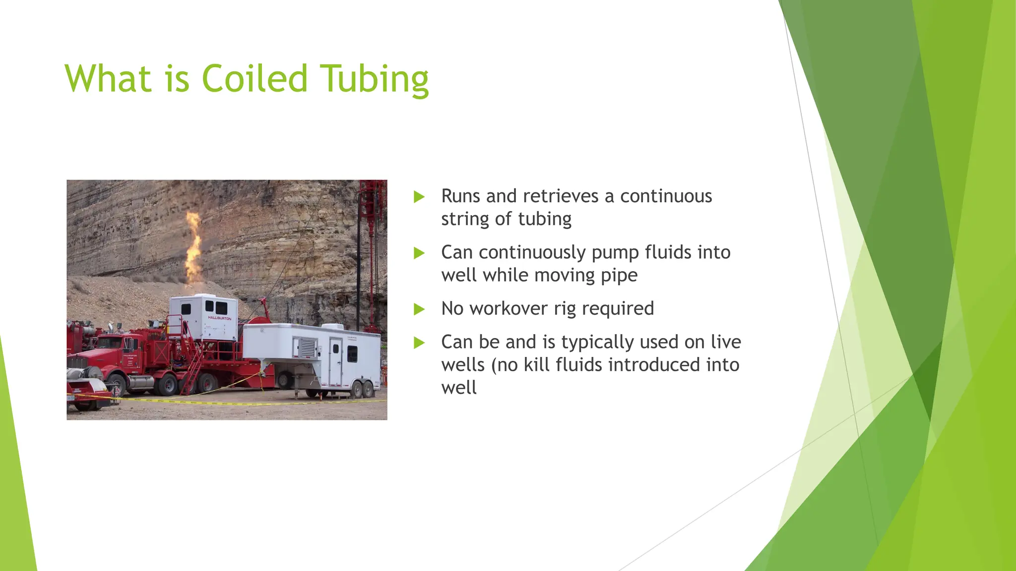
What is CoiledTubing
Runs and retrieves a continuous
string of tubing
Can continuously pump fluids into
well while moving pipe
No workover rig required
Can be and is typically used on live
wells (no kill fluids introduced into
well
3.
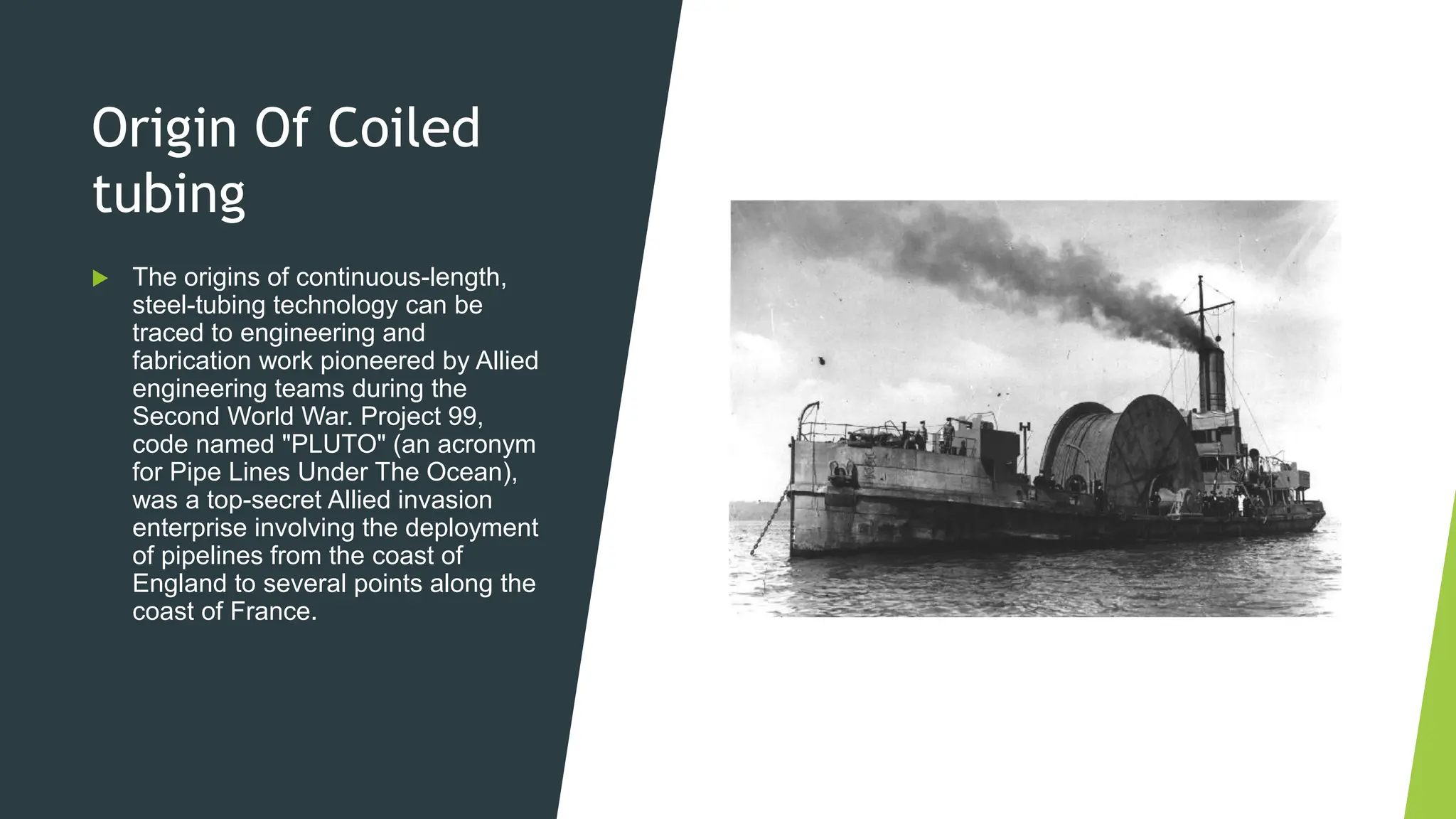
Origin Of Coiled
tubing
The origins of continuous-length,
steel-tubing technology can be
traced to engineering and
fabrication work pioneered by Allied
engineering teams during the
Second World War. Project 99,
code named "PLUTO" (an acronym
for Pipe Lines Under The Ocean),
was a top-secret Allied invasion
enterprise involving the deployment
of pipelines from the coast of
England to several points along the
coast of France.
4.
CT String
Manufacturing
and
Construction
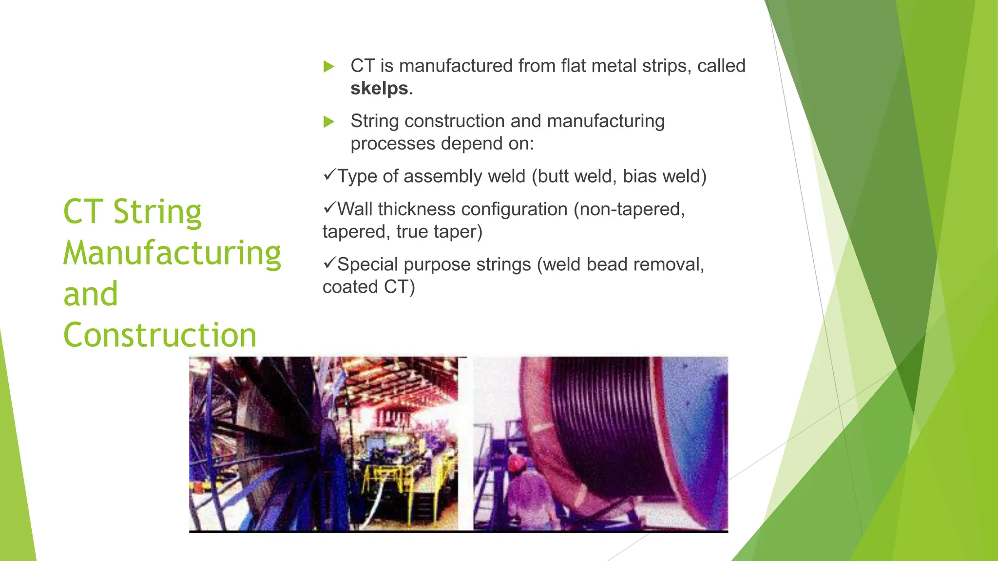
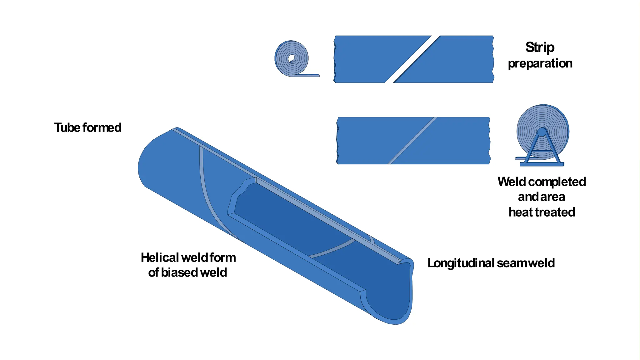
CTis manufactured from flat metal strips, called
skelps.
String construction and manufacturing
processes depend on:
✓Type of assembly weld (butt weld, bias weld)
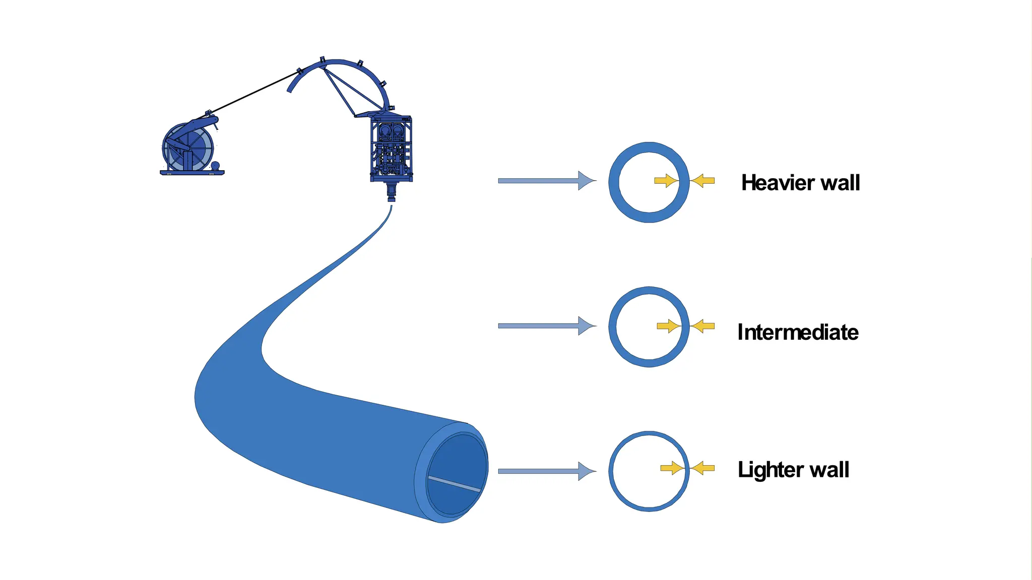
✓Wall thickness configuration (non-tapered,
tapered, true taper)
✓Special purpose strings (weld bead removal,
coated CT)
5.
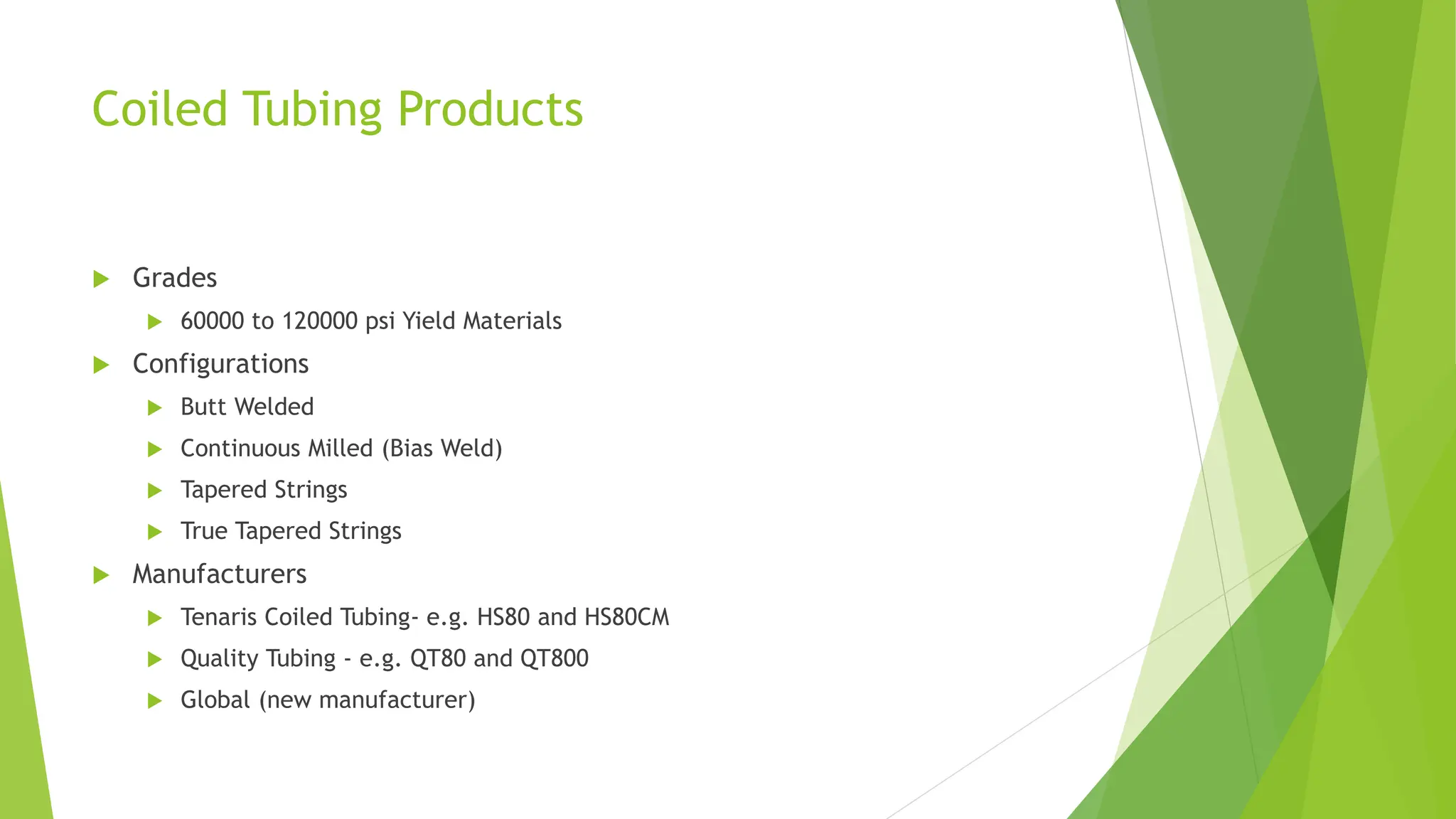
Coiled Tubing Products
Grades
60000 to 120000 psi Yield Materials
Configurations
Butt Welded
Continuous Milled (Bias Weld)
Tapered Strings
True Tapered Strings
Manufacturers
Tenaris Coiled Tubing- e.g. HS80 and HS80CM
Quality Tubing - e.g. QT80 and QT800
Global (new manufacturer)
7.
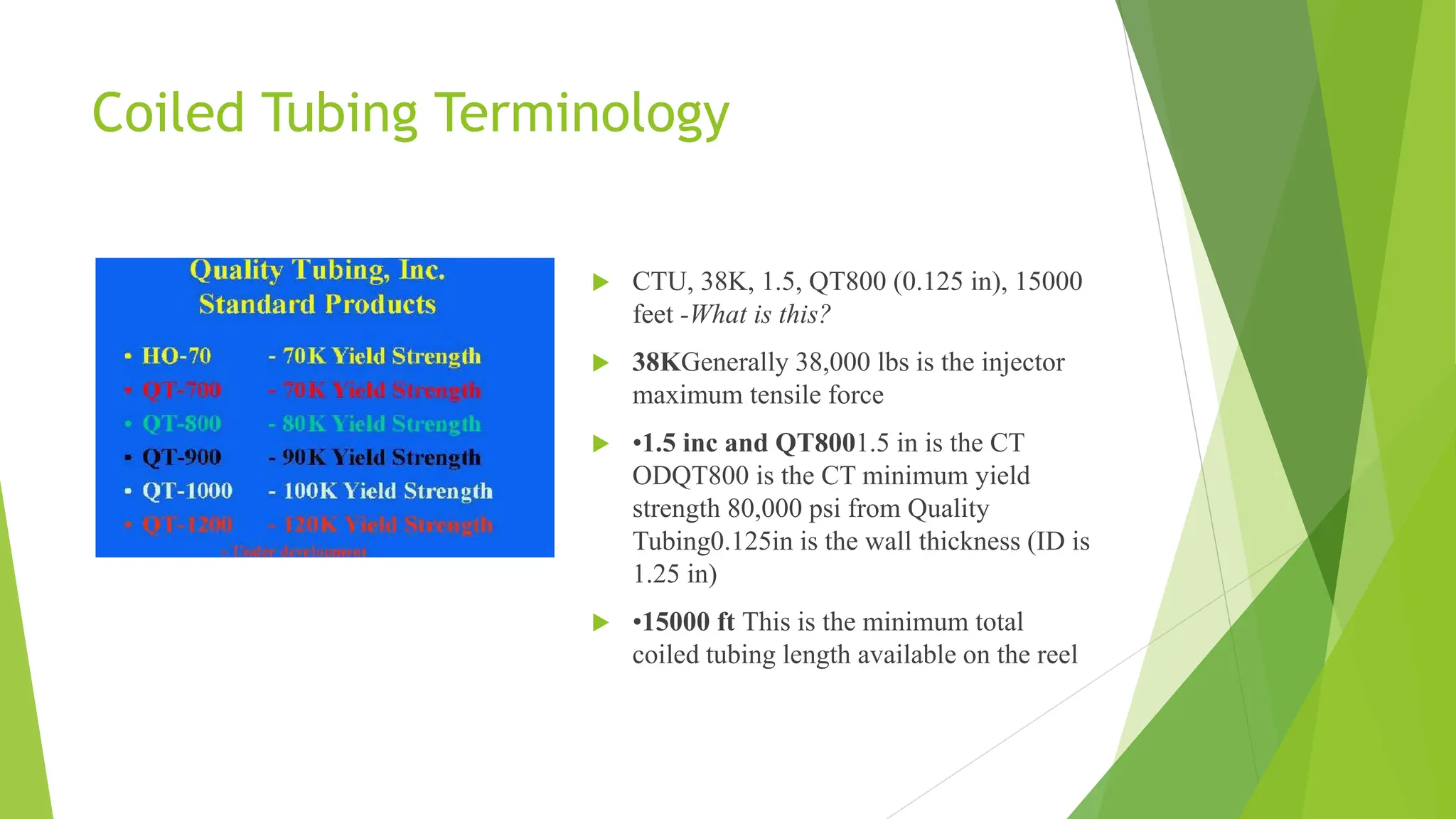
Coiled Tubing Terminology
CTU, 38K, 1.5, QT800 (0.125 in), 15000
feet -What is this?
38KGenerally 38,000 lbs is the injector
maximum tensile force
•1.5 inc and QT8001.5 in is the CT
ODQT800 is the CT minimum yield
strength 80,000 psi from Quality
Tubing0.125in is the wall thickness (ID is
1.25 in)
•15000 ft This is the minimum total
coiled tubing length available on the reel
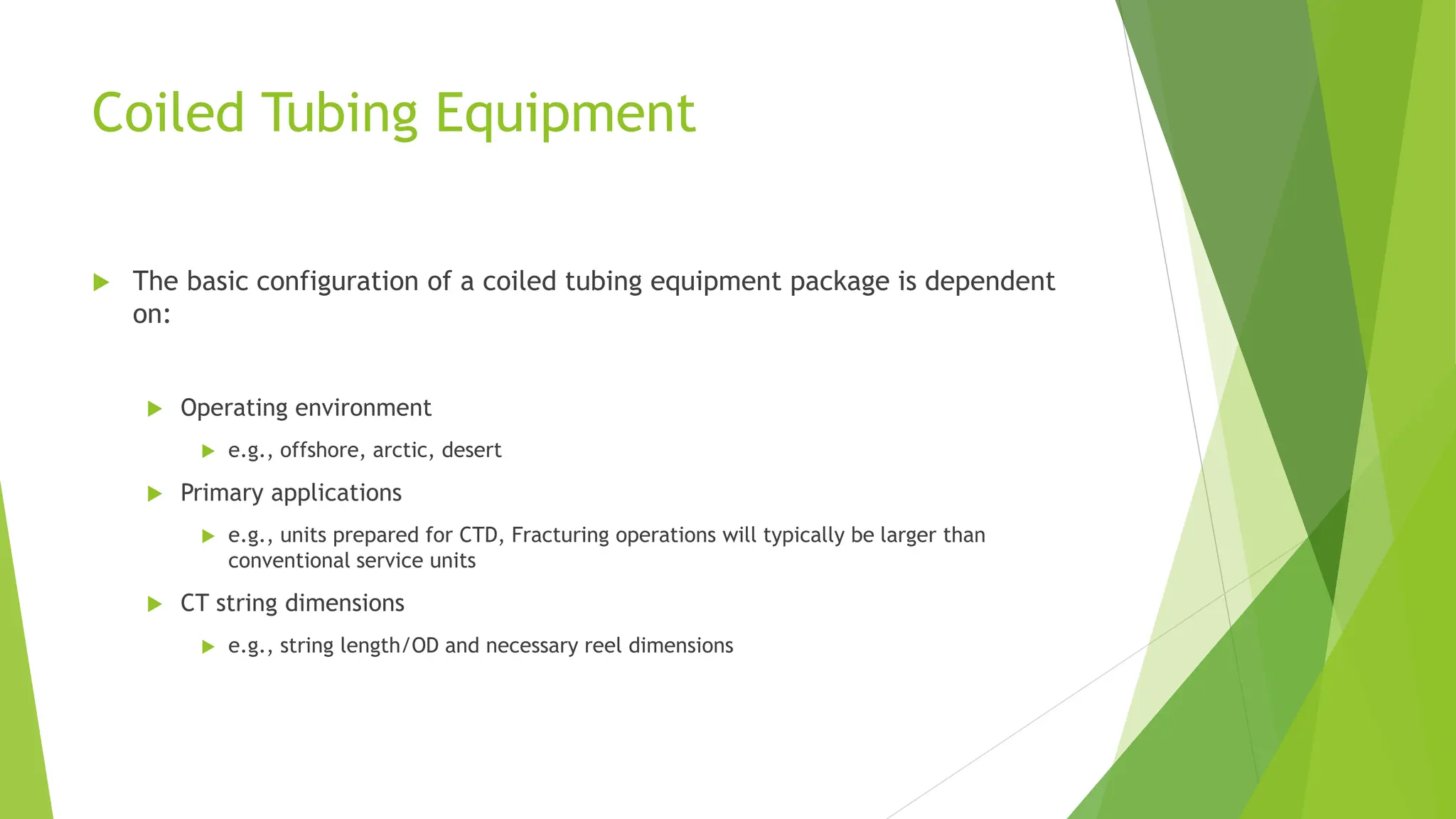
Coiled Tubing Equipment
The basic configuration of a coiled tubing equipment package is dependent
on:
Operating environment
e.g., offshore, arctic, desert
Primary applications
e.g., units prepared for CTD, Fracturing operations will typically be larger than
conventional service units
CT string dimensions
e.g., string length/OD and necessary reel dimensions
12.
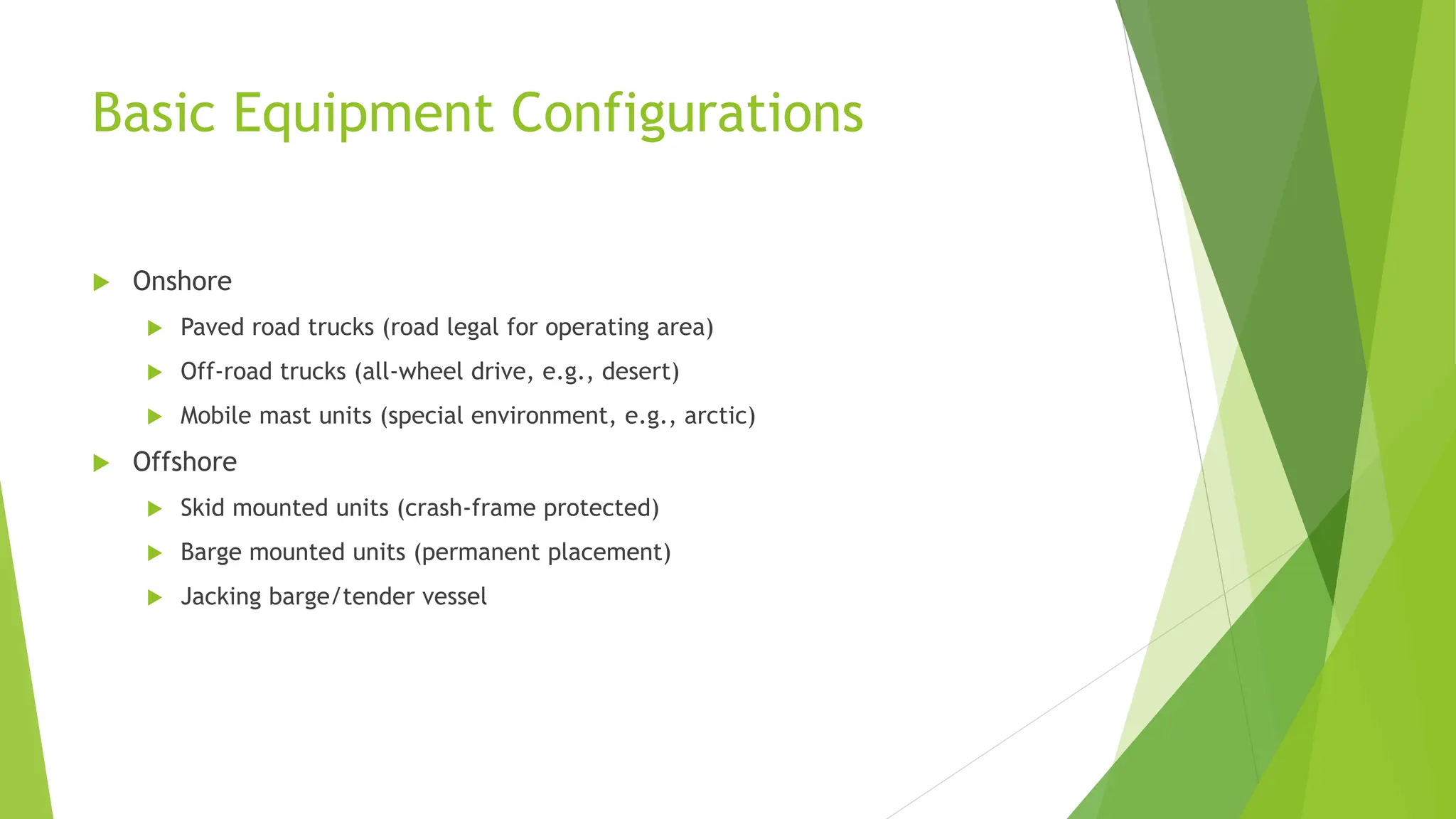
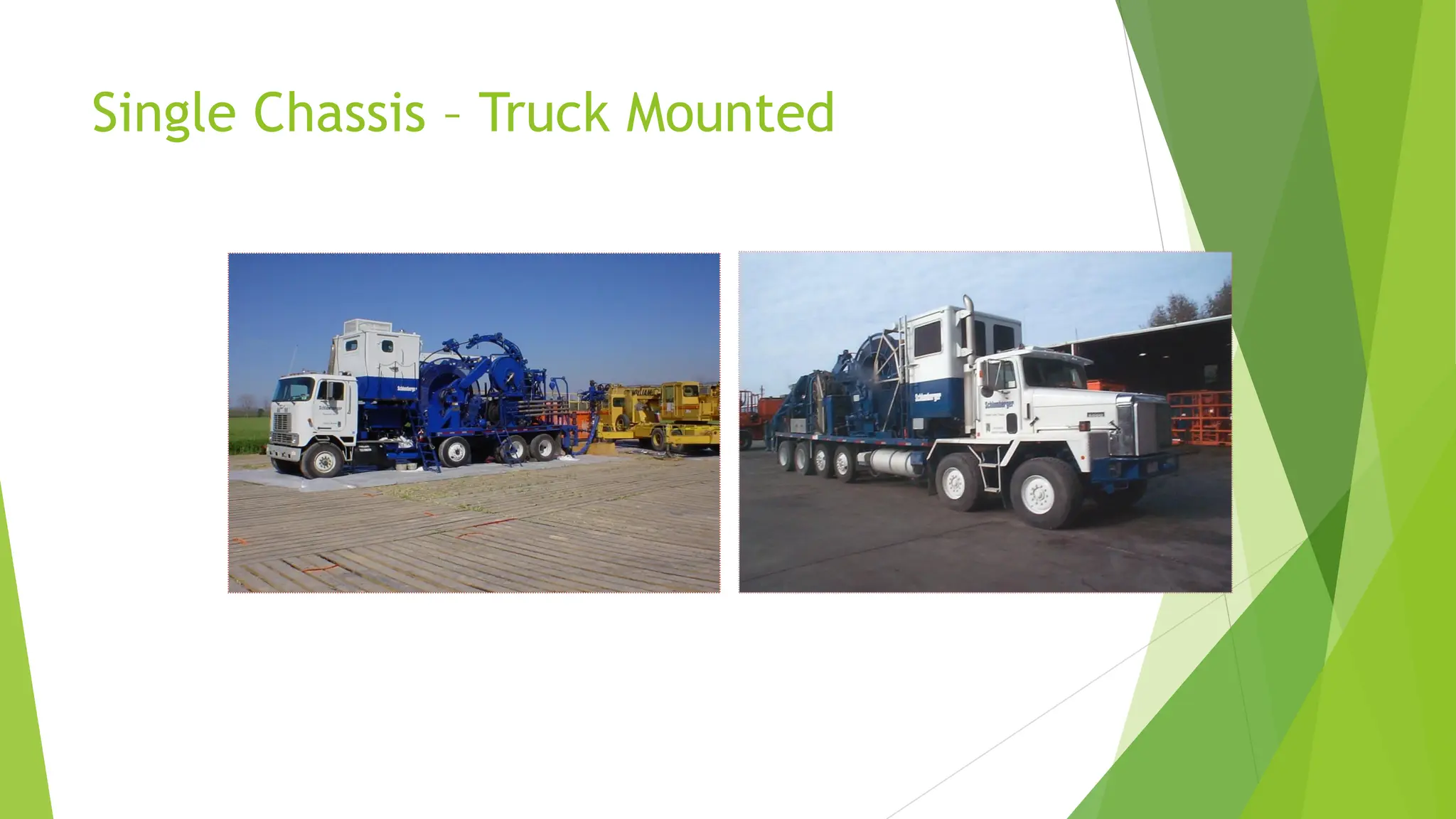
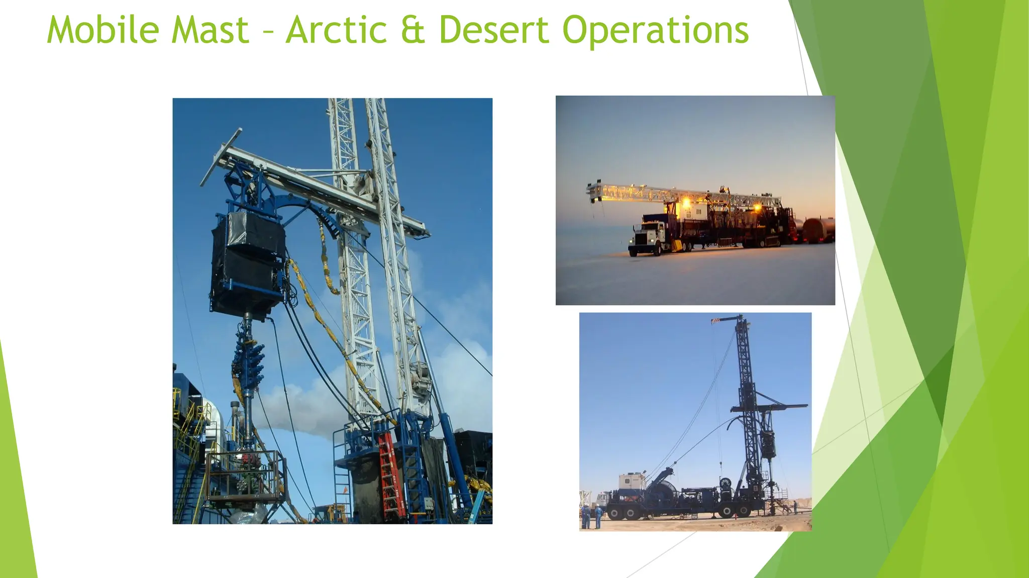
Basic Equipment Configurations
Onshore
Paved road trucks (road legal for operating area)
Off-road trucks (all-wheel drive, e.g., desert)
Mobile mast units (special environment, e.g., arctic)
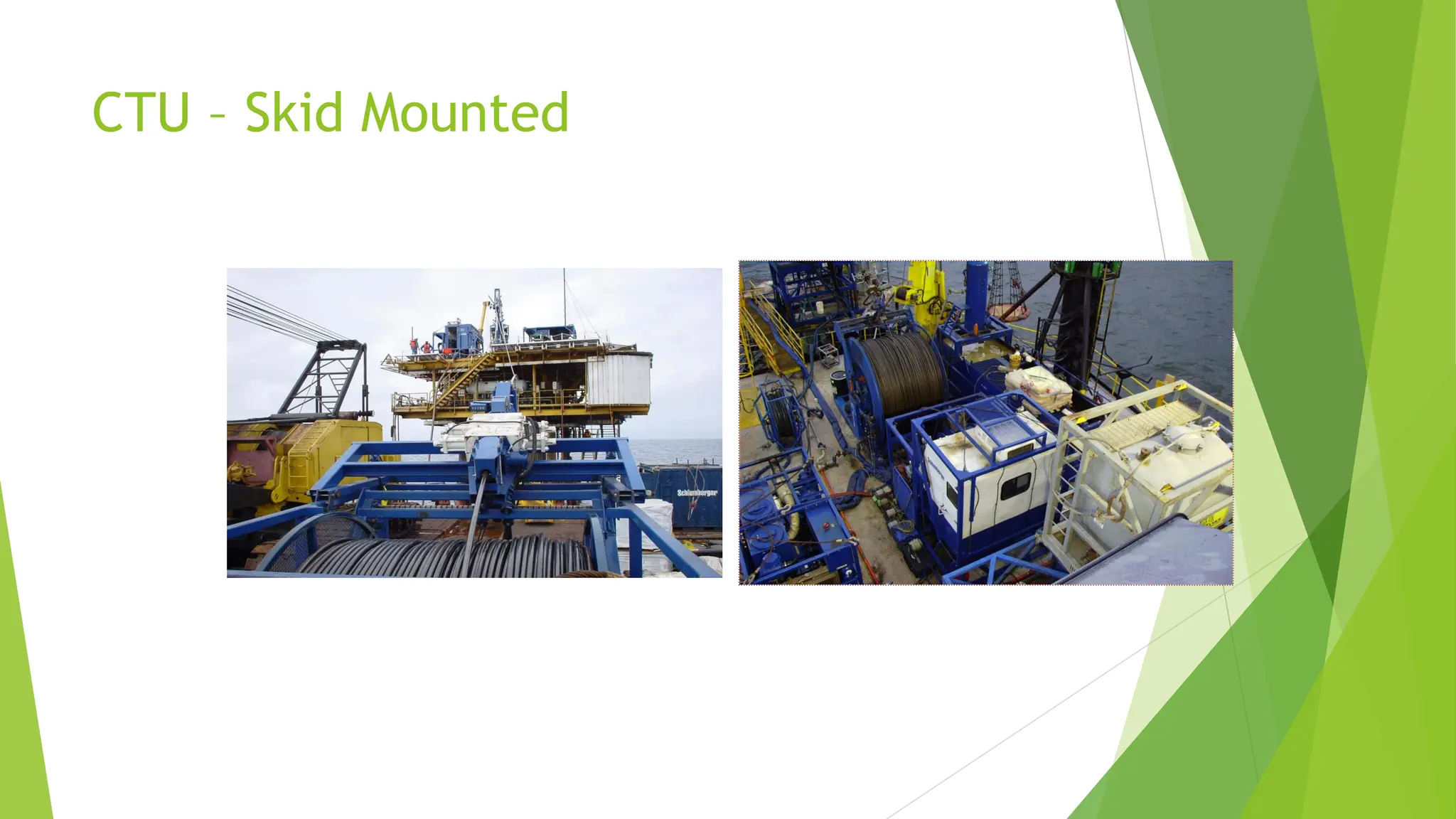
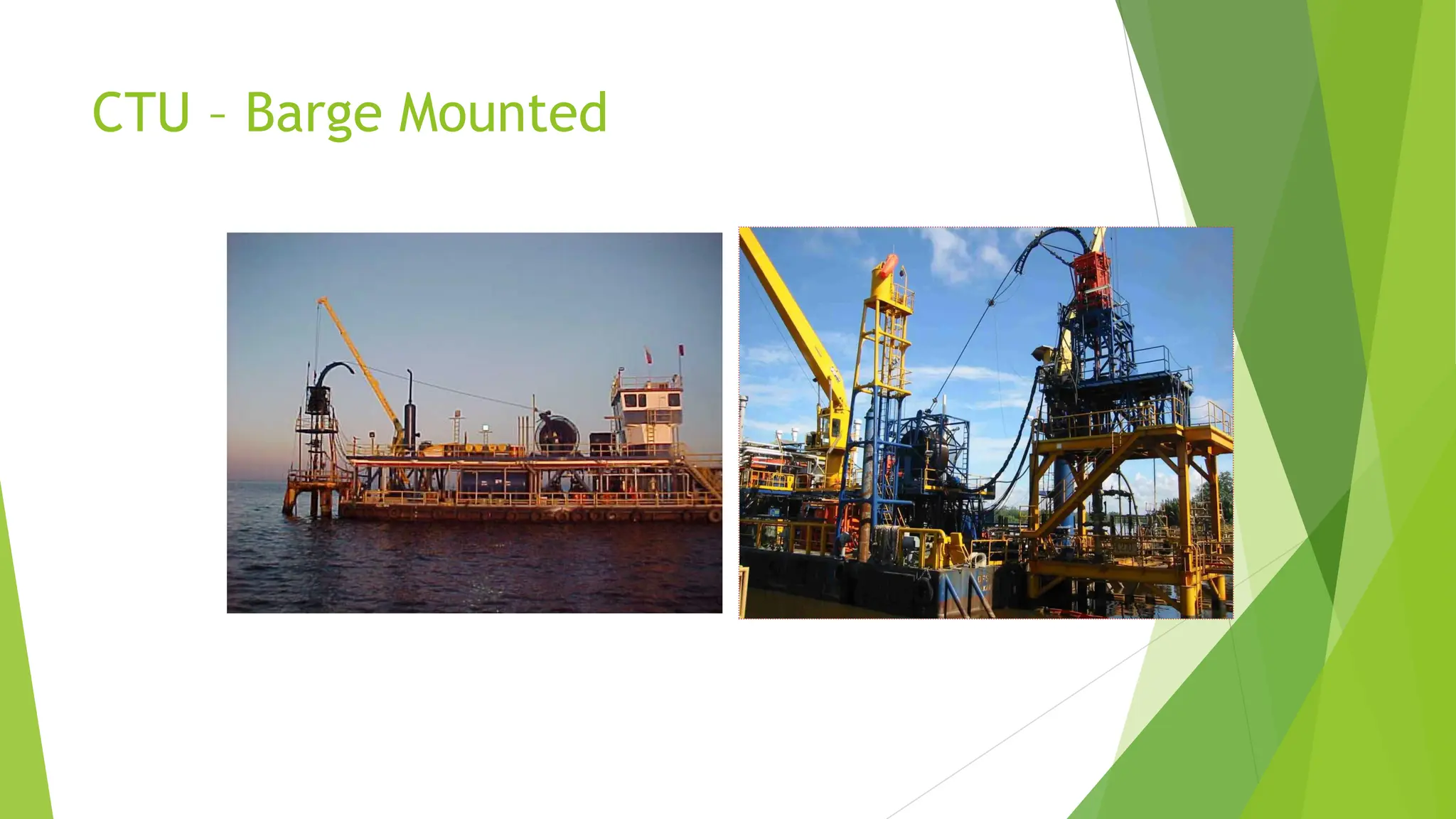
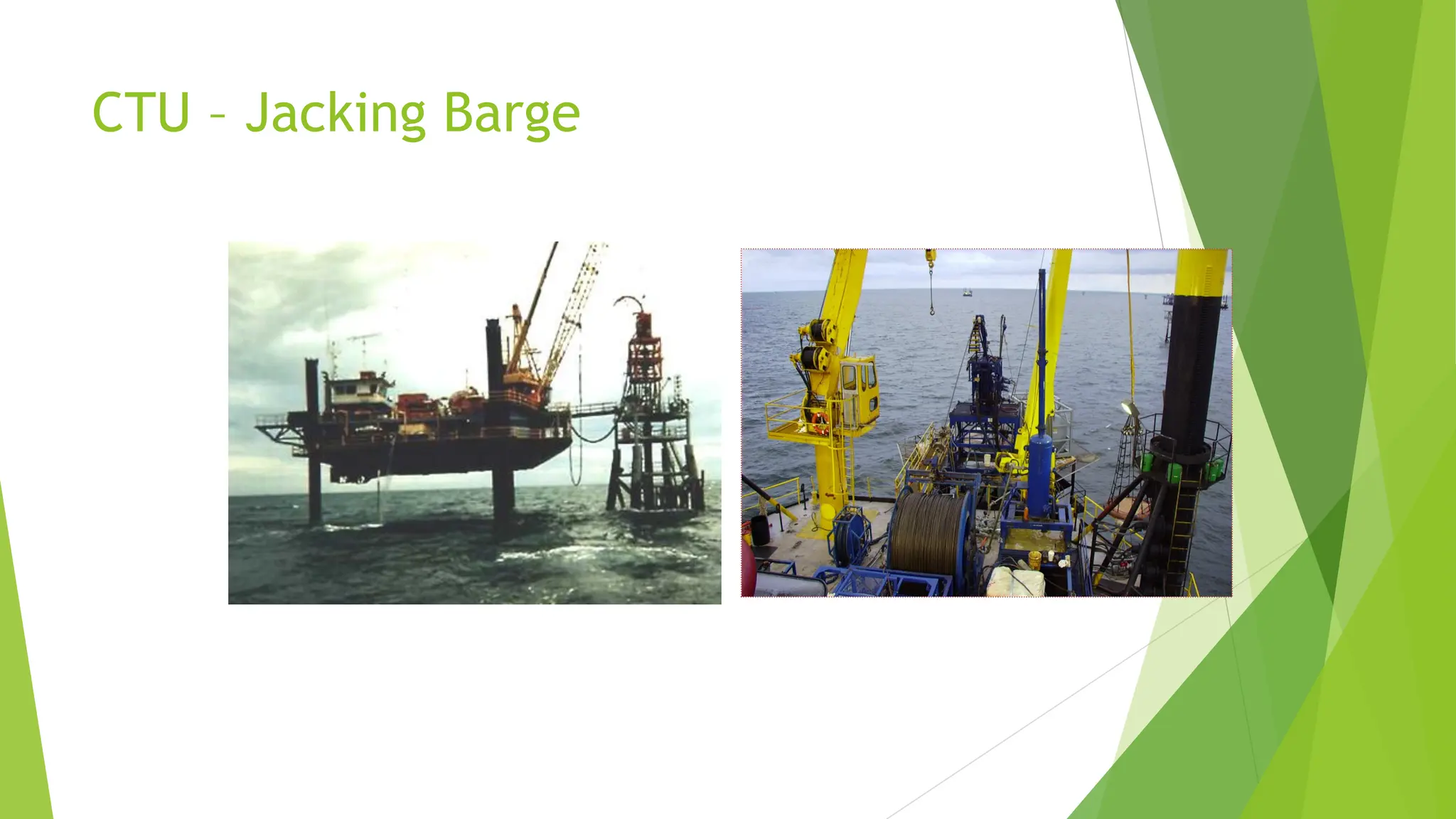
Offshore
Skid mounted units (crash-frame protected)
Barge mounted units (permanent placement)
Jacking barge/tender vessel
13.
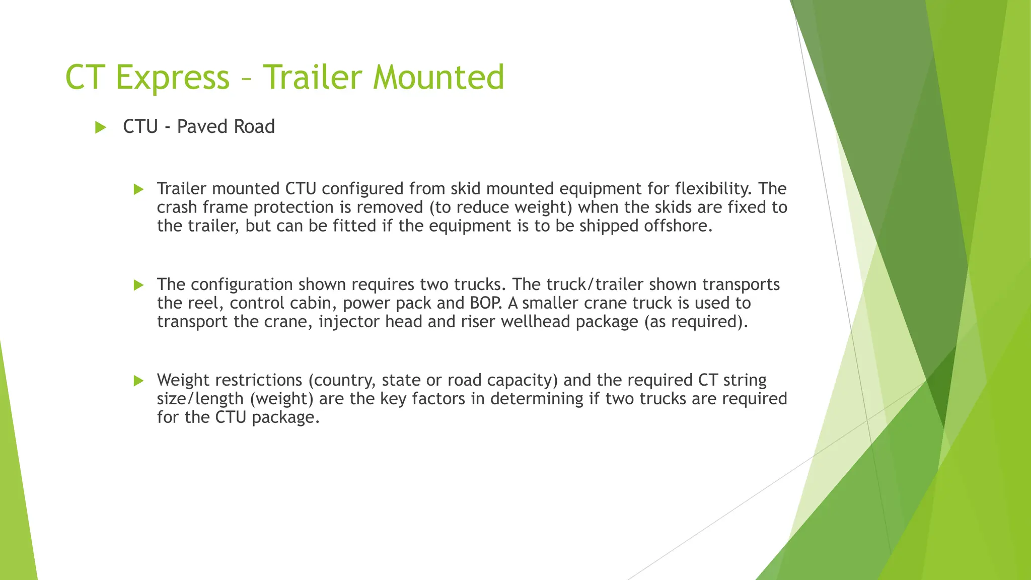
CT Express –Trailer Mounted
CTU - Paved Road
Trailer mounted CTU configured from skid mounted equipment for flexibility. The
crash frame protection is removed (to reduce weight) when the skids are fixed to
the trailer, but can be fitted if the equipment is to be shipped offshore.
The configuration shown requires two trucks. The truck/trailer shown transports
the reel, control cabin, power pack and BOP. A smaller crane truck is used to
transport the crane, injector head and riser wellhead package (as required).
Weight restrictions (country, state or road capacity) and the required CT string
size/length (weight) are the key factors in determining if two trucks are required
for the CTU package.
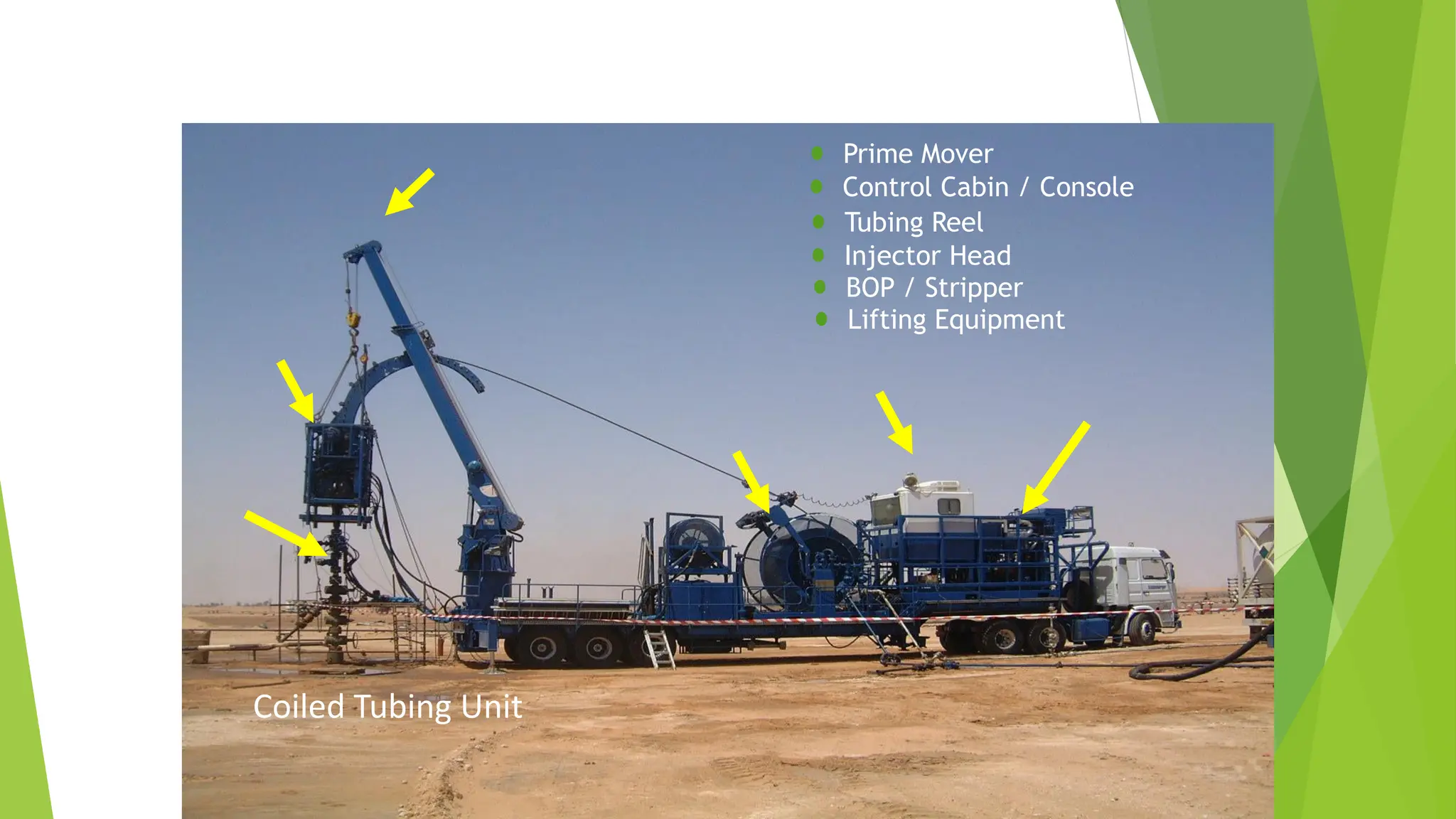
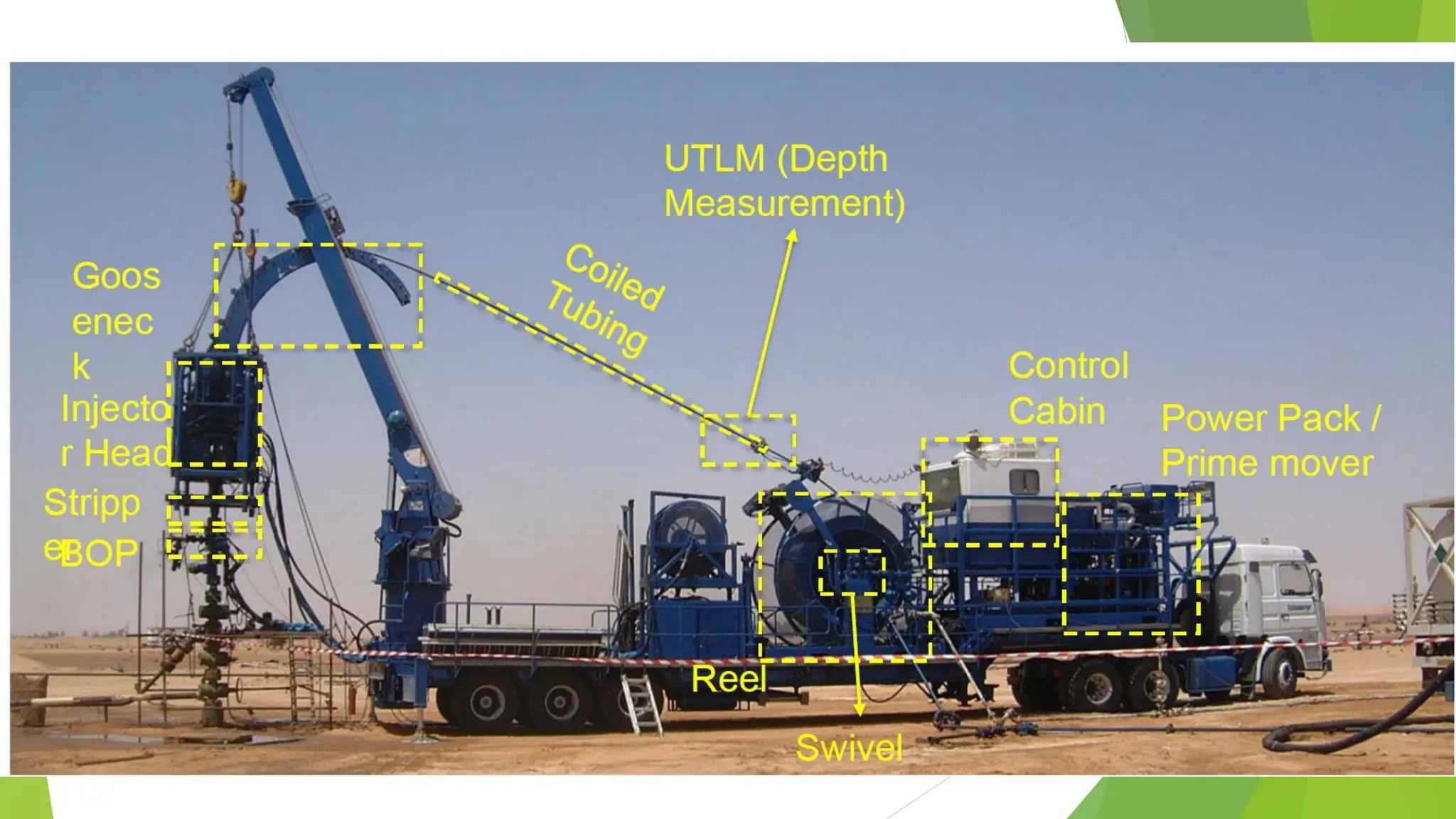
Main CT EquipmentPackage
Coiled Tubing Unit
Prime Mover
Control Cabin / Console
Tubing Reel
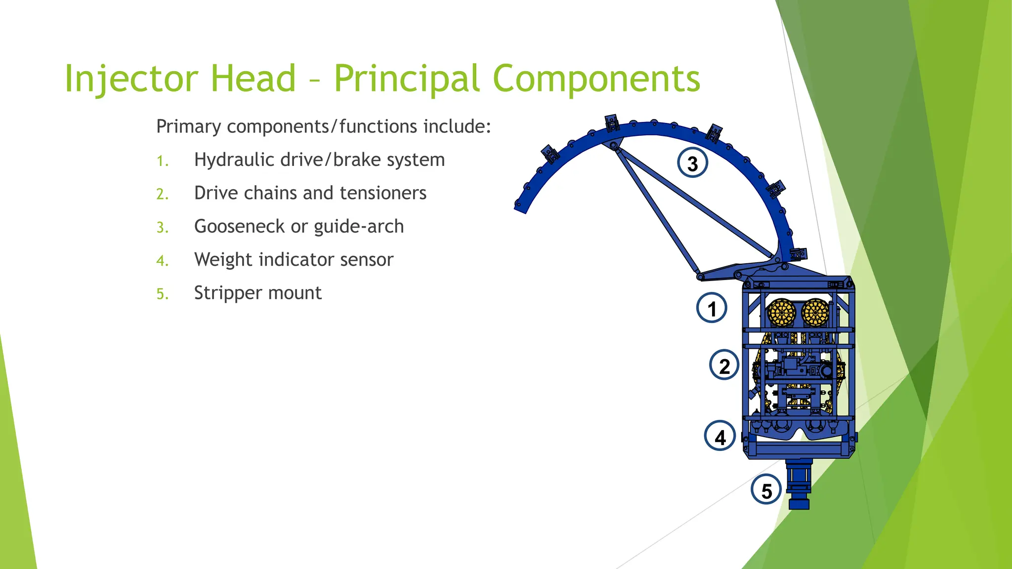
Injector Head
BOP / Stripper
Lifting Equipment
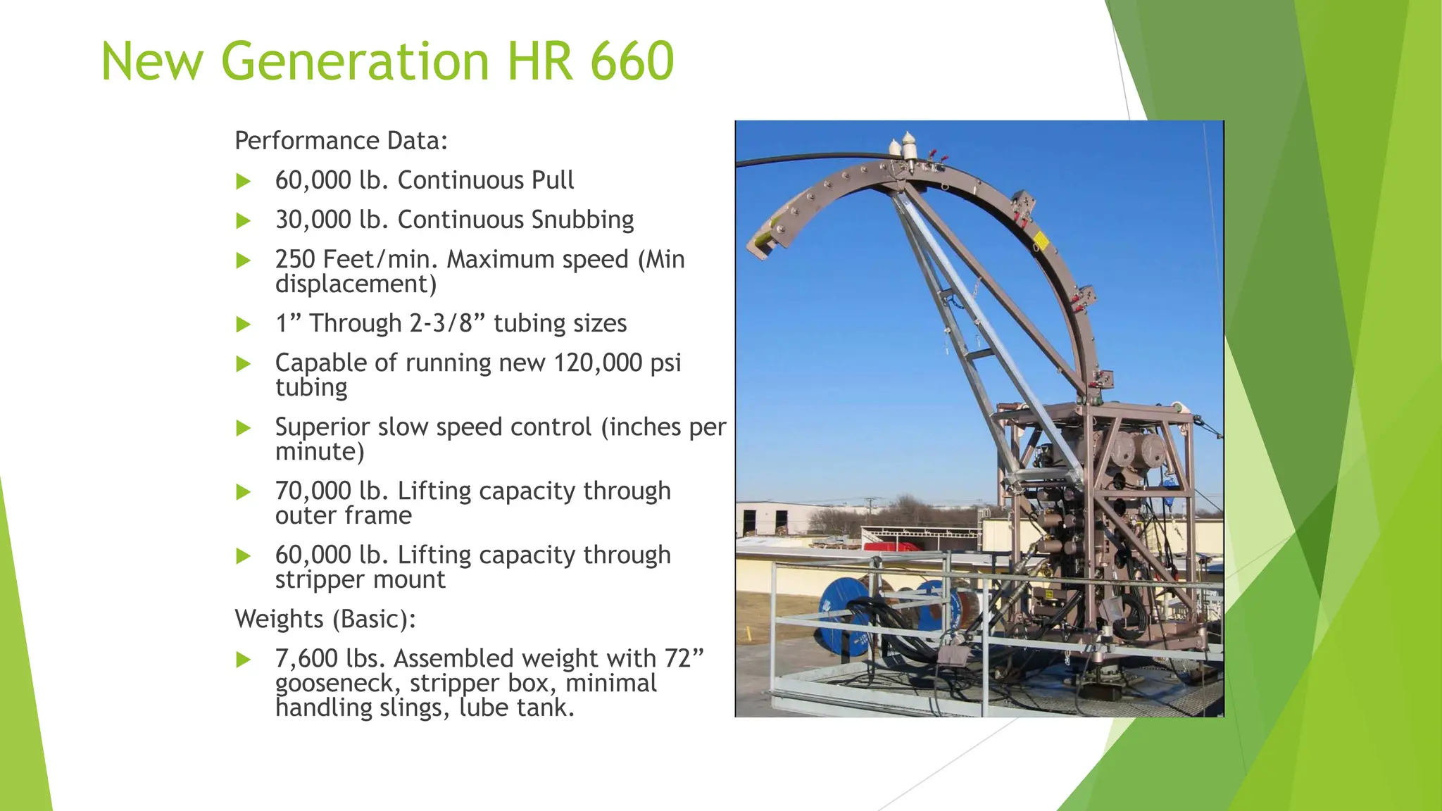
21.
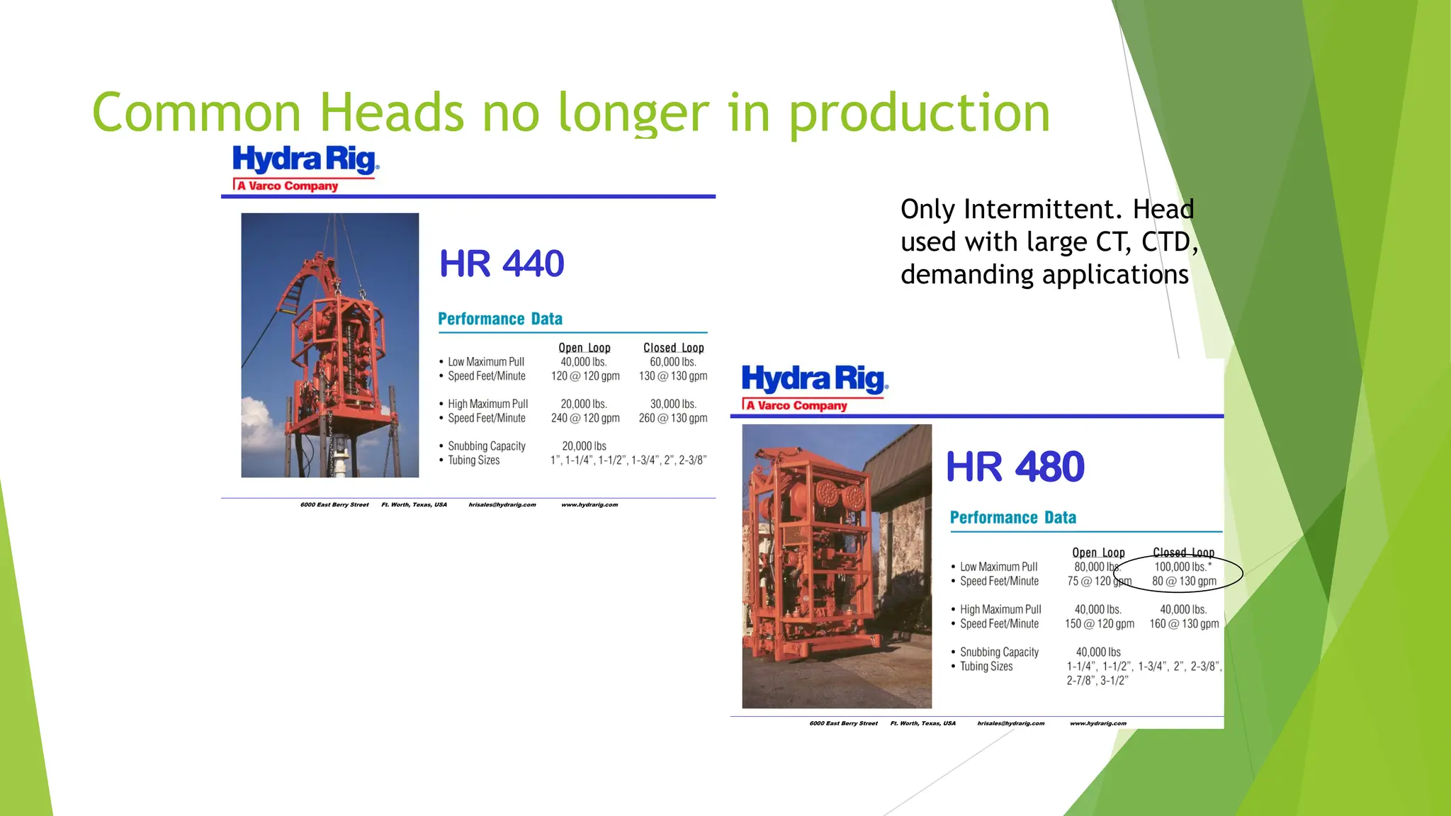
Common Heads nolonger in production
6000 East Berry Street Ft. Worth, Texas, USA hrisales@hydrarig.com www.hydrarig.com
HR 440
6000 East Berry Street Ft. Worth, Texas, USA hrisales@hydrarig.com www.hydrarig.com
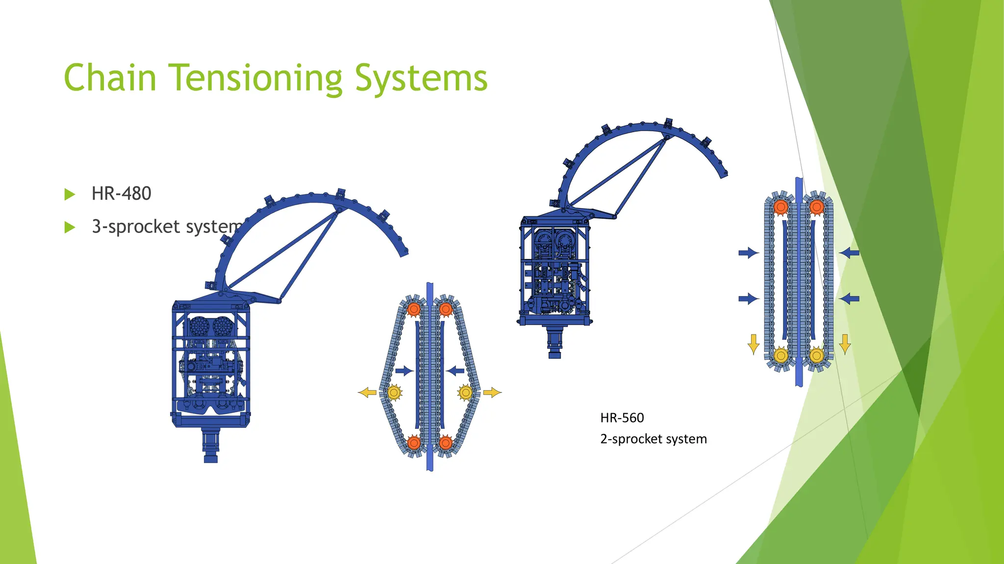
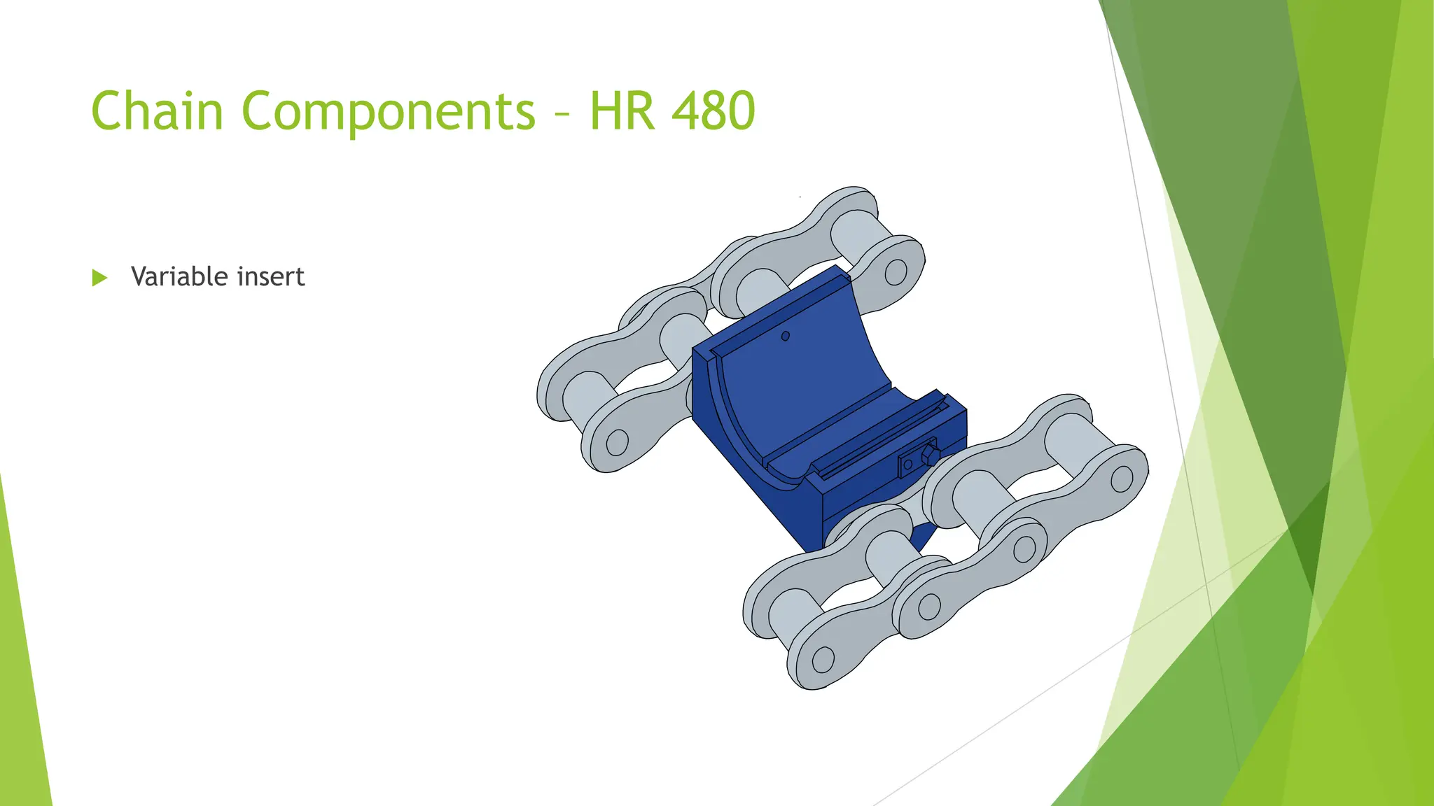
HR 480
Only Intermittent. Head
used with large CT, CTD,
demanding applications
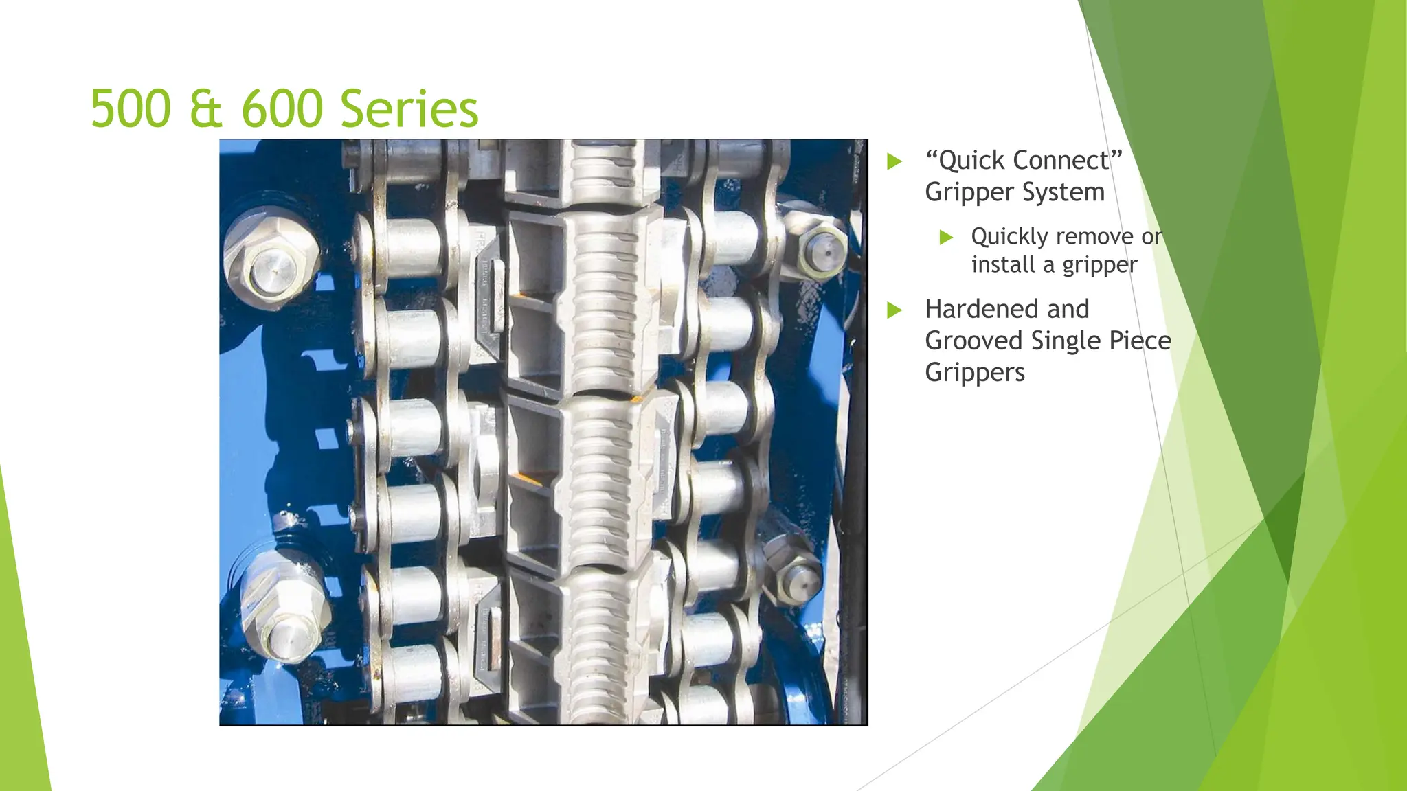
500 & 600Series
“Quick Connect”
Gripper System
Quickly remove or
install a gripper
Hardened and
Grooved Single Piece
Grippers
33.
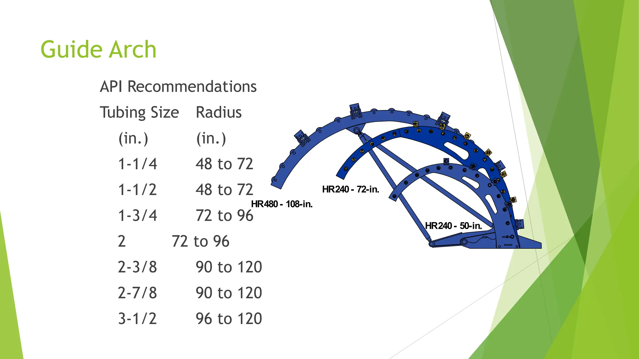
Guide Arch
API Recommendations
TubingSize Radius
(in.) (in.)
1-1/4 48 to 72
1-1/2 48 to 72
1-3/4 72 to 96
2 72 to 96
2-3/8 90 to 120
2-7/8 90 to 120
3-1/2 96 to 120
HR240- 50-in.
HR480- 108-in.
HR240- 72-in.
34.
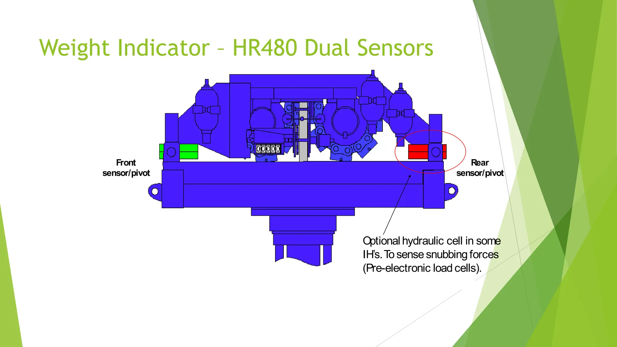
Weight Indicator –HR480 Dual Sensors
Front
sensor/pivot
Rear
sensor/pivot
Optional hydraulic cell in some
IH’s.To sense snubbing forces
(Pre-electronic load cells).
35.
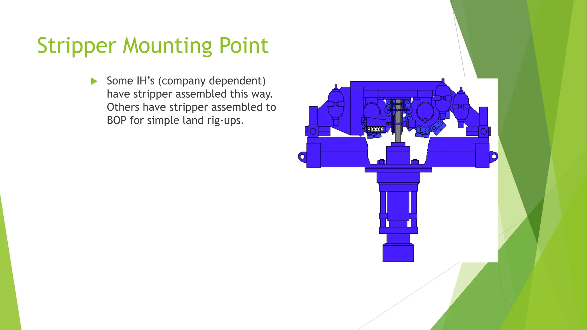
Stripper Mounting Point
Some IH’s (company dependent)
have stripper assembled this way.
Others have stripper assembled to
BOP for simple land rig-ups.
36.
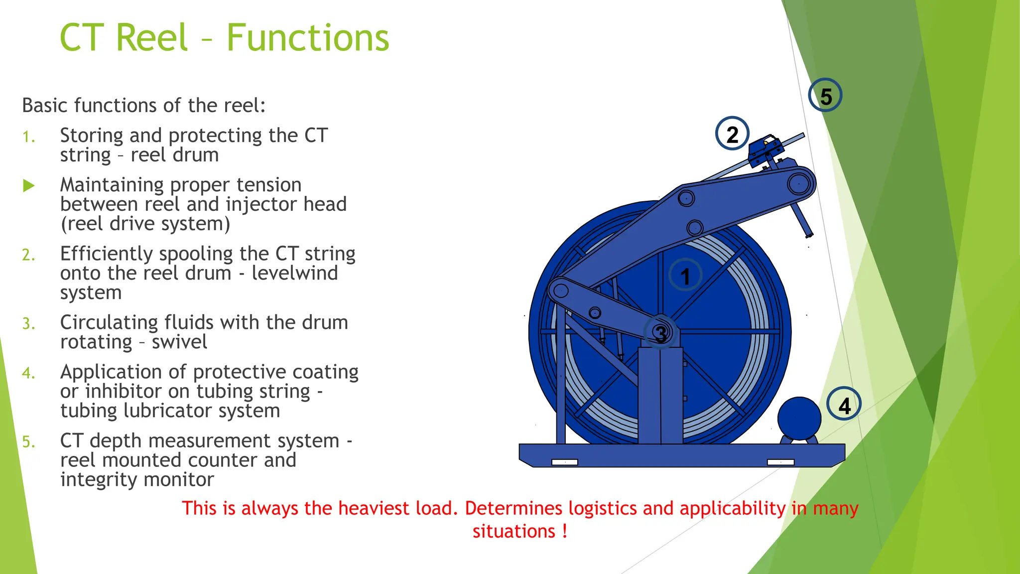
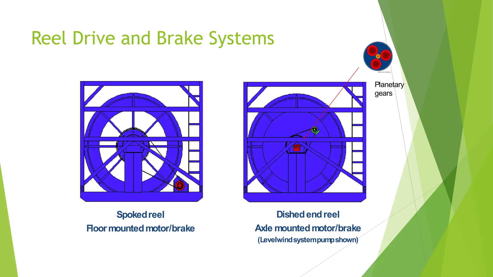
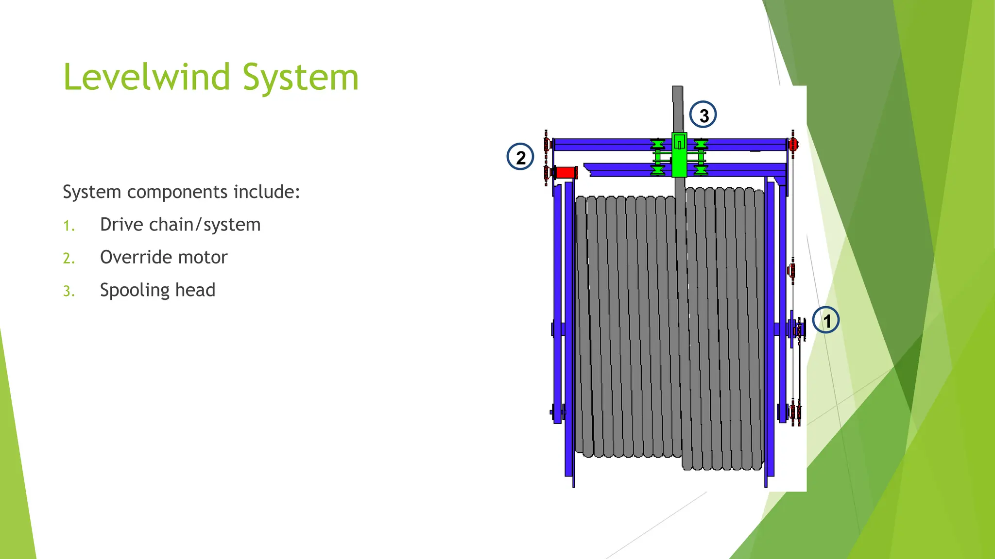
CT Reel –Functions
Basic functions of the reel:
1. Storing and protecting the CT
string – reel drum
Maintaining proper tension
between reel and injector head
(reel drive system)
2. Efficiently spooling the CT string
onto the reel drum - levelwind
system
3. Circulating fluids with the drum
rotating – swivel
4. Application of protective coating
or inhibitor on tubing string -
tubing lubricator system
5. CT depth measurement system -
reel mounted counter and
integrity monitor
This is always the heaviest load. Determines logistics and applicability in many
situations !
1
2
3
4
5
1
3
37.
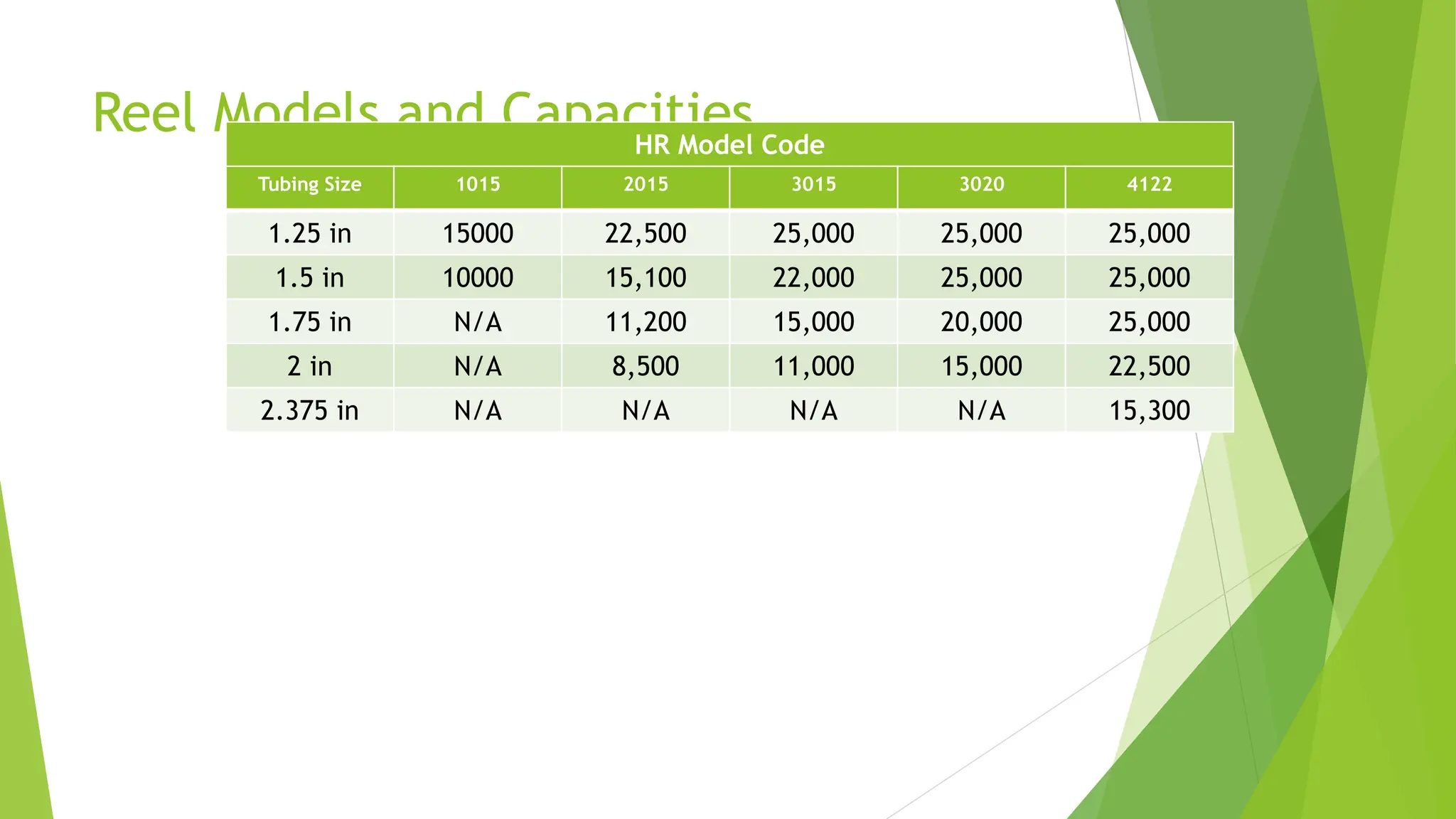
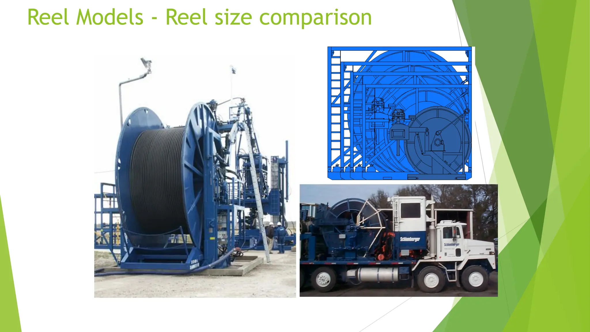
Reel Models andCapacities
HR Model Code
Tubing Size 1015 2015 3015 3020 4122
1.25 in 15000 22,500 25,000 25,000 25,000
1.5 in 10000 15,100 22,000 25,000 25,000
1.75 in N/A 11,200 15,000 20,000 25,000
2 in N/A 8,500 11,000 15,000 22,500
2.375 in N/A N/A N/A N/A 15,300
38.
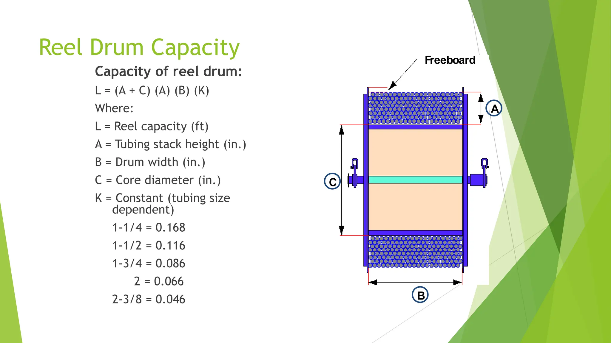
Reel Drum Capacity
Capacityof reel drum:
L = (A + C) (A) (B) (K)
Where:
L = Reel capacity (ft)
A = Tubing stack height (in.)
B = Drum width (in.)
C = Core diameter (in.)
K = Constant (tubing size
dependent)
1-1/4 = 0.168
1-1/2 = 0.116
1-3/4 = 0.086
2 = 0.066
2-3/8 = 0.046
Freeboard
A
B
C
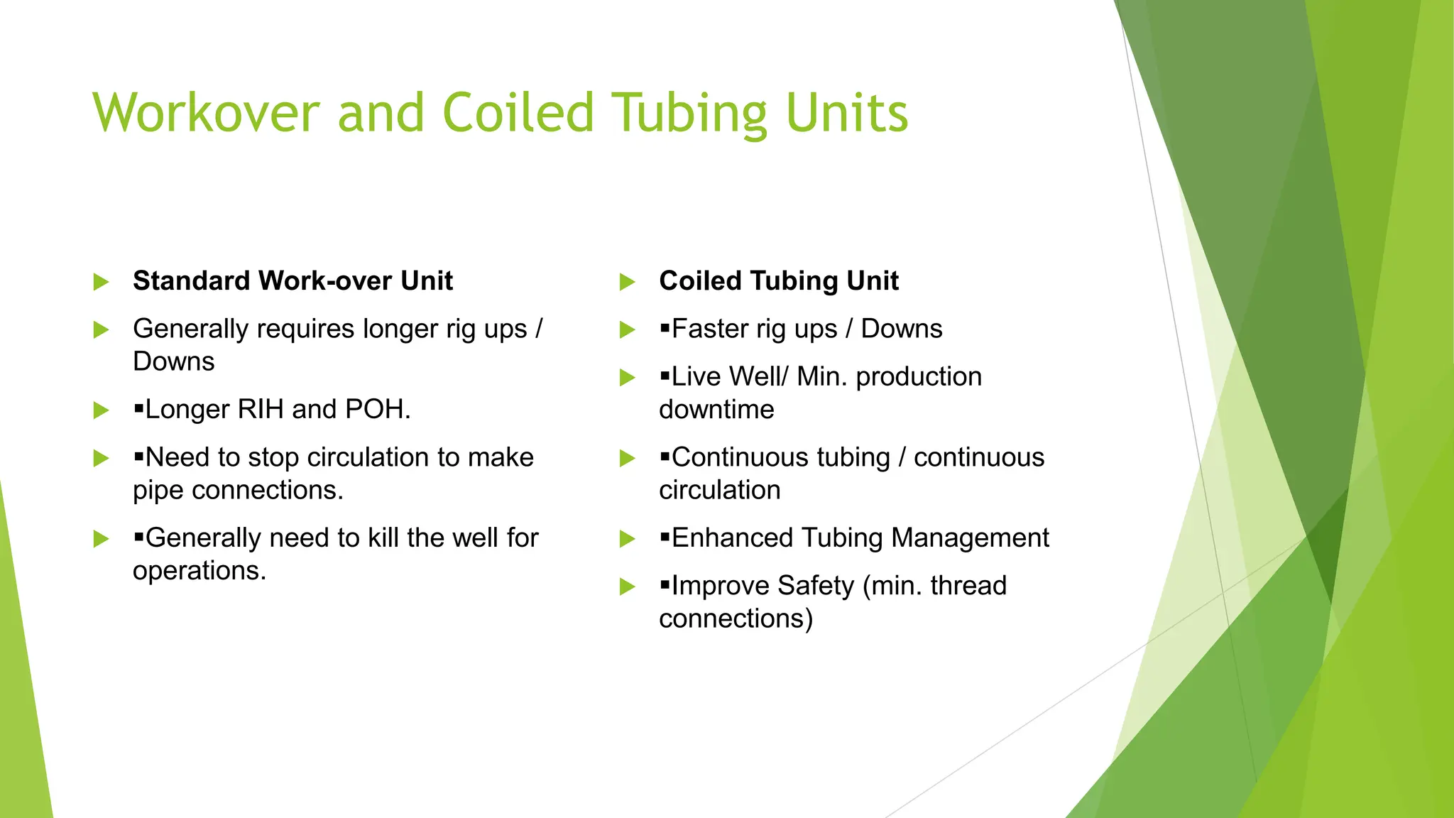
Workover and CoiledTubing Units
Standard Work-over Unit
Generally requires longer rig ups /
Downs
▪Longer RIH and POH.
▪Need to stop circulation to make
pipe connections.
▪Generally need to kill the well for
operations.
Coiled Tubing Unit
▪Faster rig ups / Downs
▪Live Well/ Min. production
downtime
▪Continuous tubing / continuous
circulation
▪Enhanced Tubing Management
▪Improve Safety (min. thread
connections)
44.
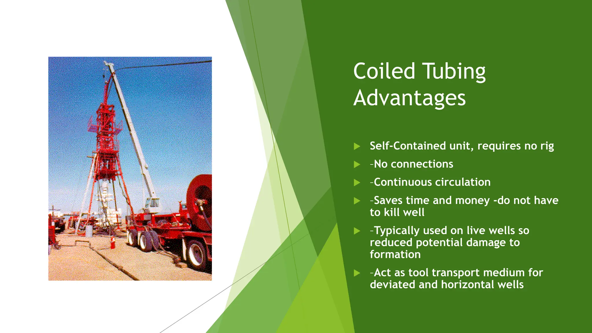
Coiled Tubing
Advantages
Self-Containedunit, requires no rig
–No connections
–Continuous circulation
–Saves time and money -do not have
to kill well
–Typically used on live wells so
reduced potential damage to
formation
–Act as tool transport medium for
deviated and horizontal wells
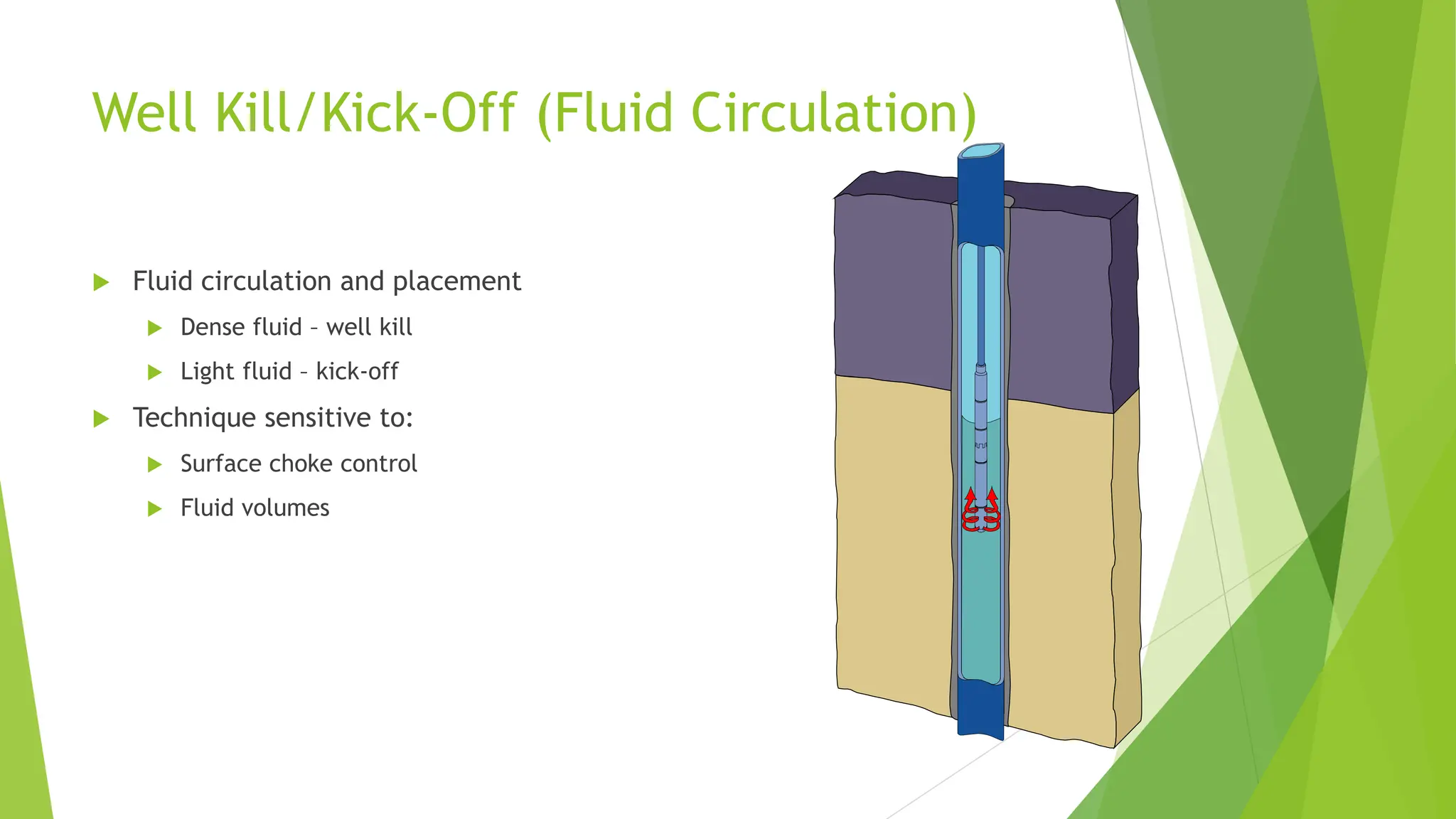
Well Kill/Kick-Off (FluidCirculation)
Fluid circulation and placement
Dense fluid – well kill
Light fluid – kick-off
Technique sensitive to:
Surface choke control
Fluid volumes
51.
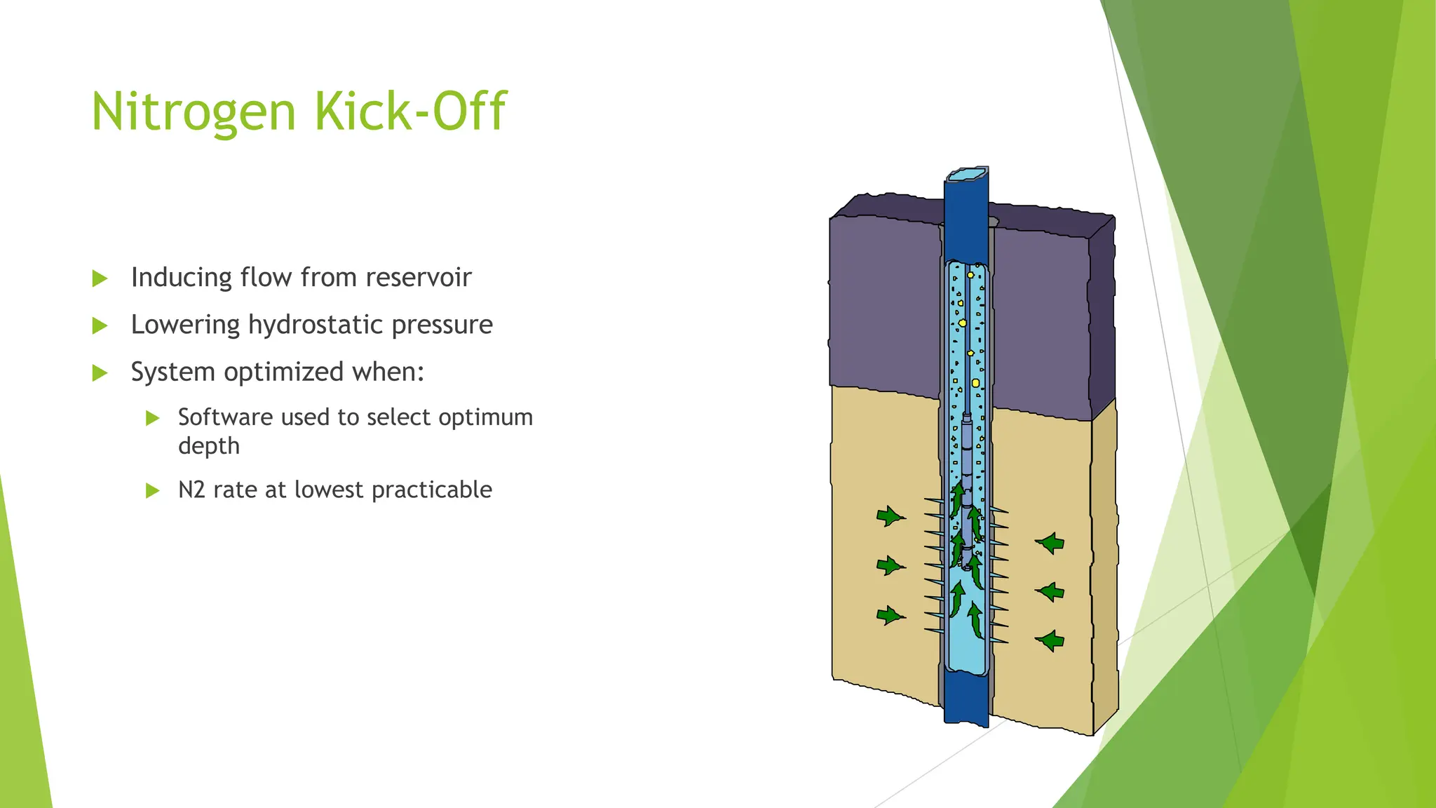
Nitrogen Kick-Off
Inducingflow from reservoir
Lowering hydrostatic pressure
System optimized when:
Software used to select optimum
depth
N2 rate at lowest practicable
52.
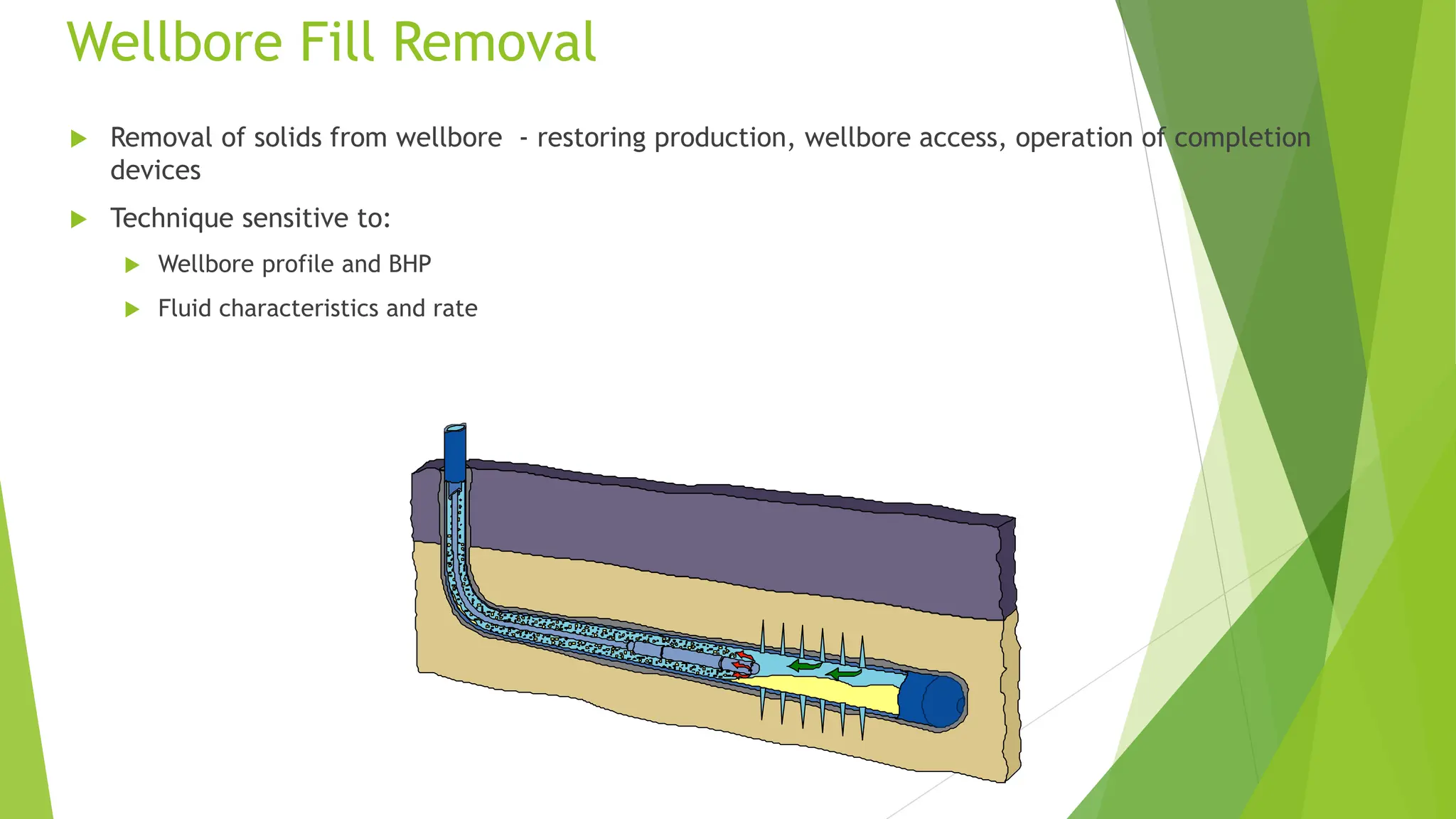
Wellbore Fill Removal
Removal of solids from wellbore - restoring production, wellbore access, operation of completion
devices
Technique sensitive to:
Wellbore profile and BHP
Fluid characteristics and rate
53.
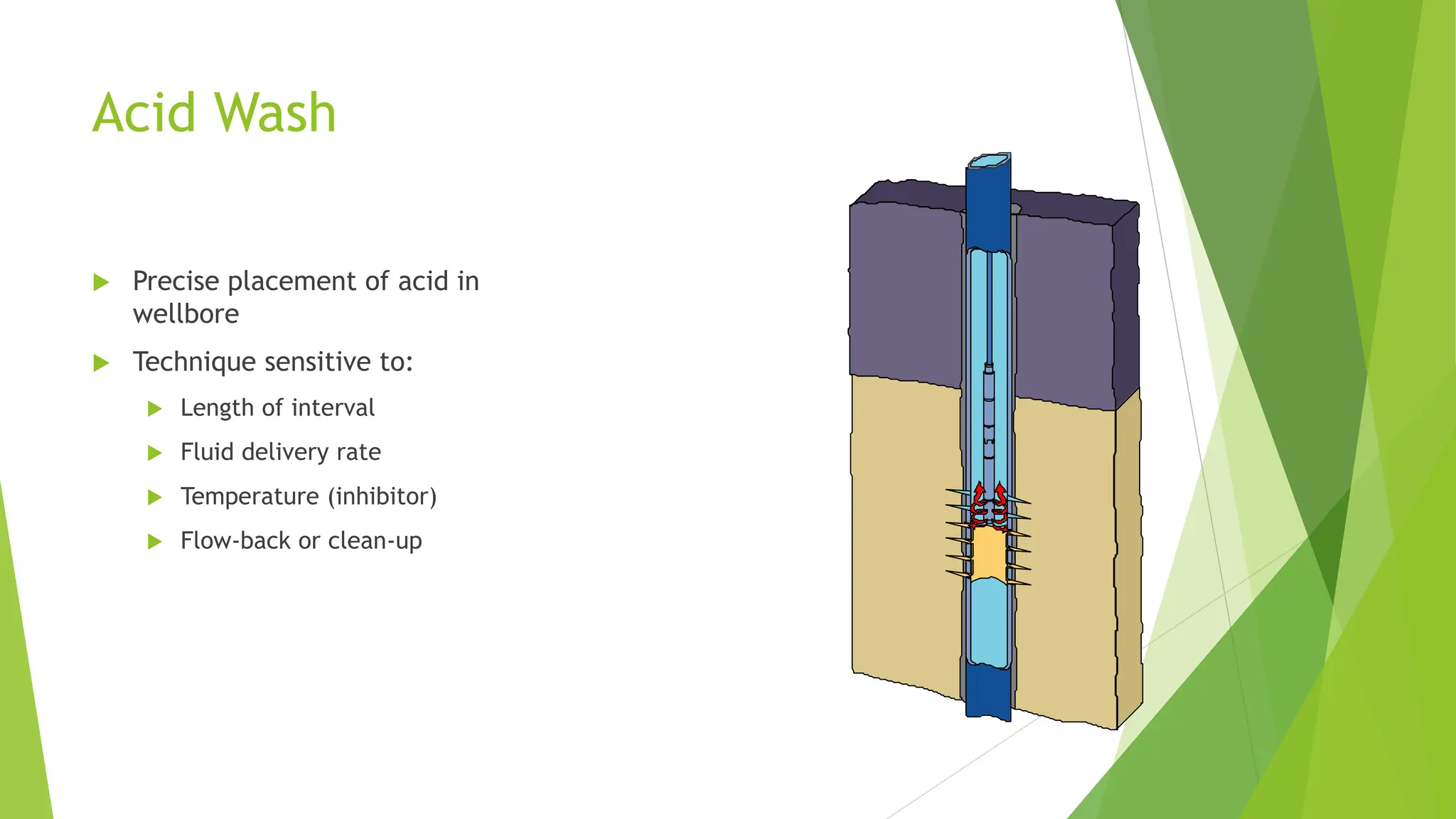
Acid Wash
Preciseplacement of acid in
wellbore
Technique sensitive to:
Length of interval
Fluid delivery rate
Temperature (inhibitor)
Flow-back or clean-up
54.
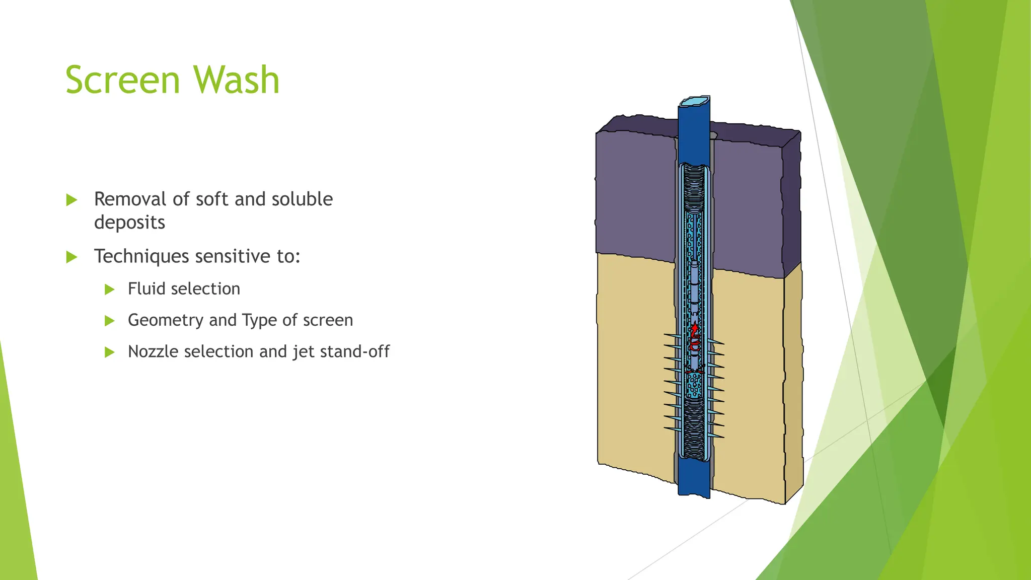
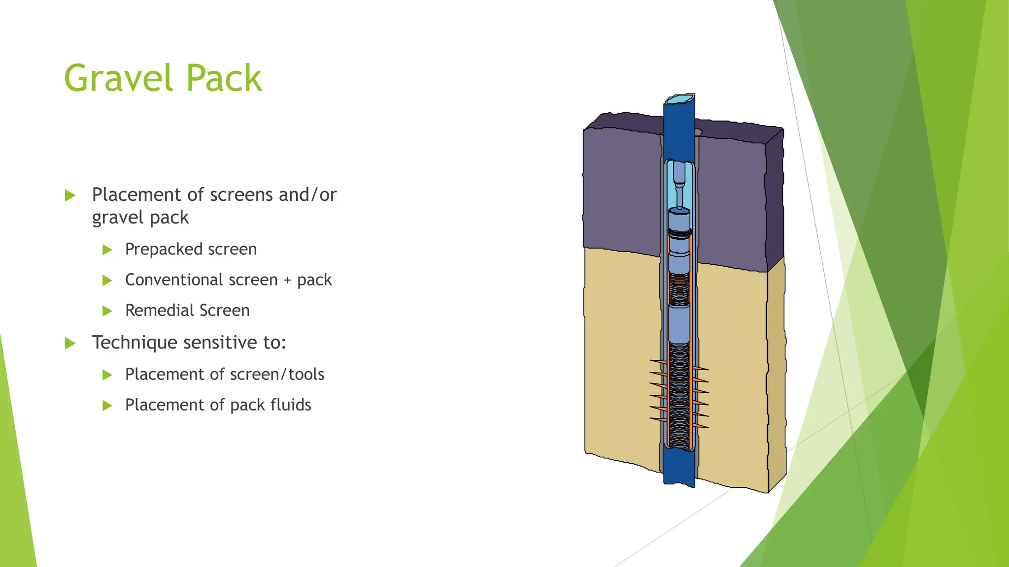
Screen Wash
Removalof soft and soluble
deposits
Techniques sensitive to:
Fluid selection
Geometry and Type of screen
Nozzle selection and jet stand-off
55.
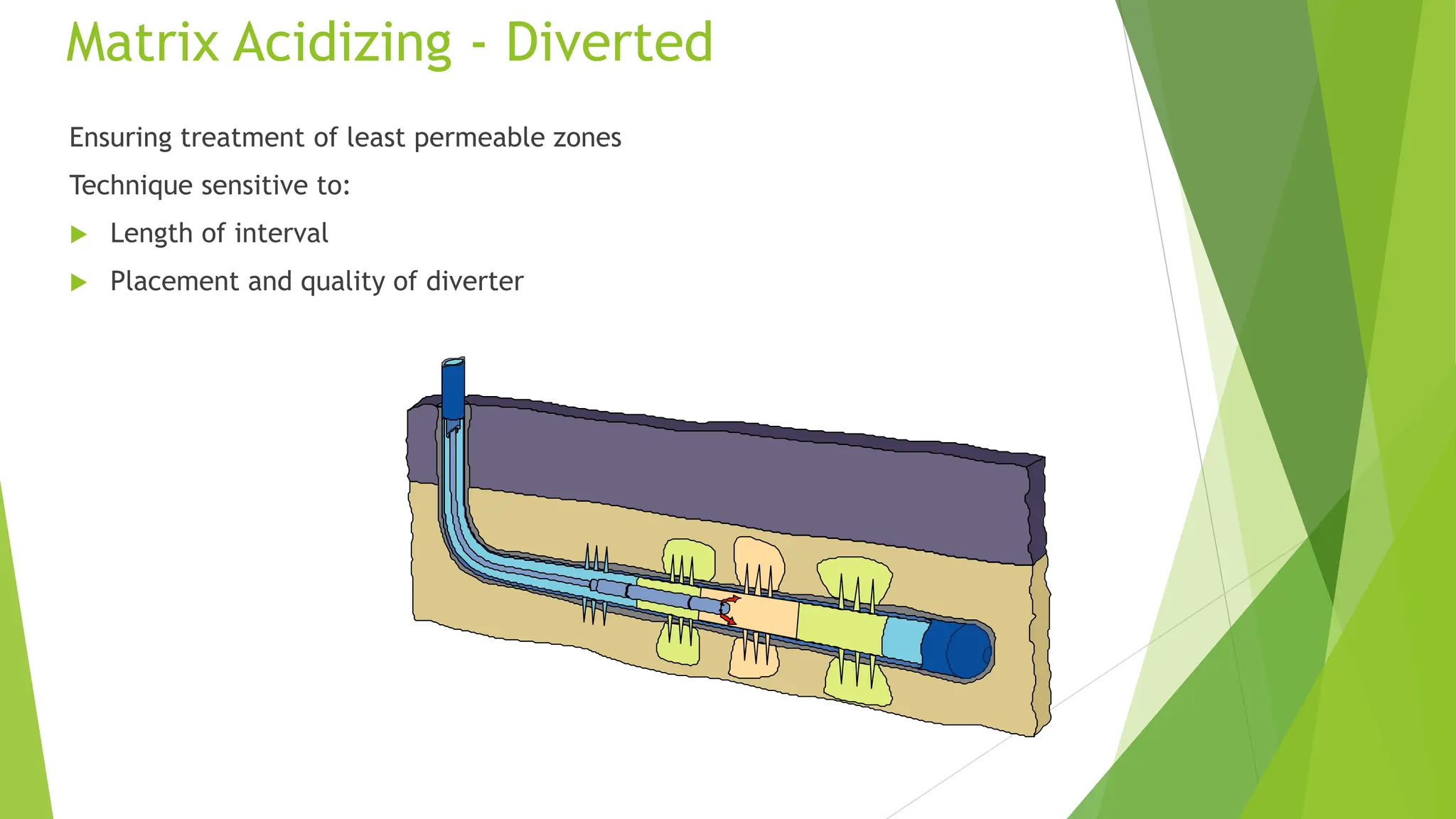
Matrix Acidizing -Diverted
Ensuring treatment of least permeable zones
Technique sensitive to:
Length of interval
Placement and quality of diverter
56.
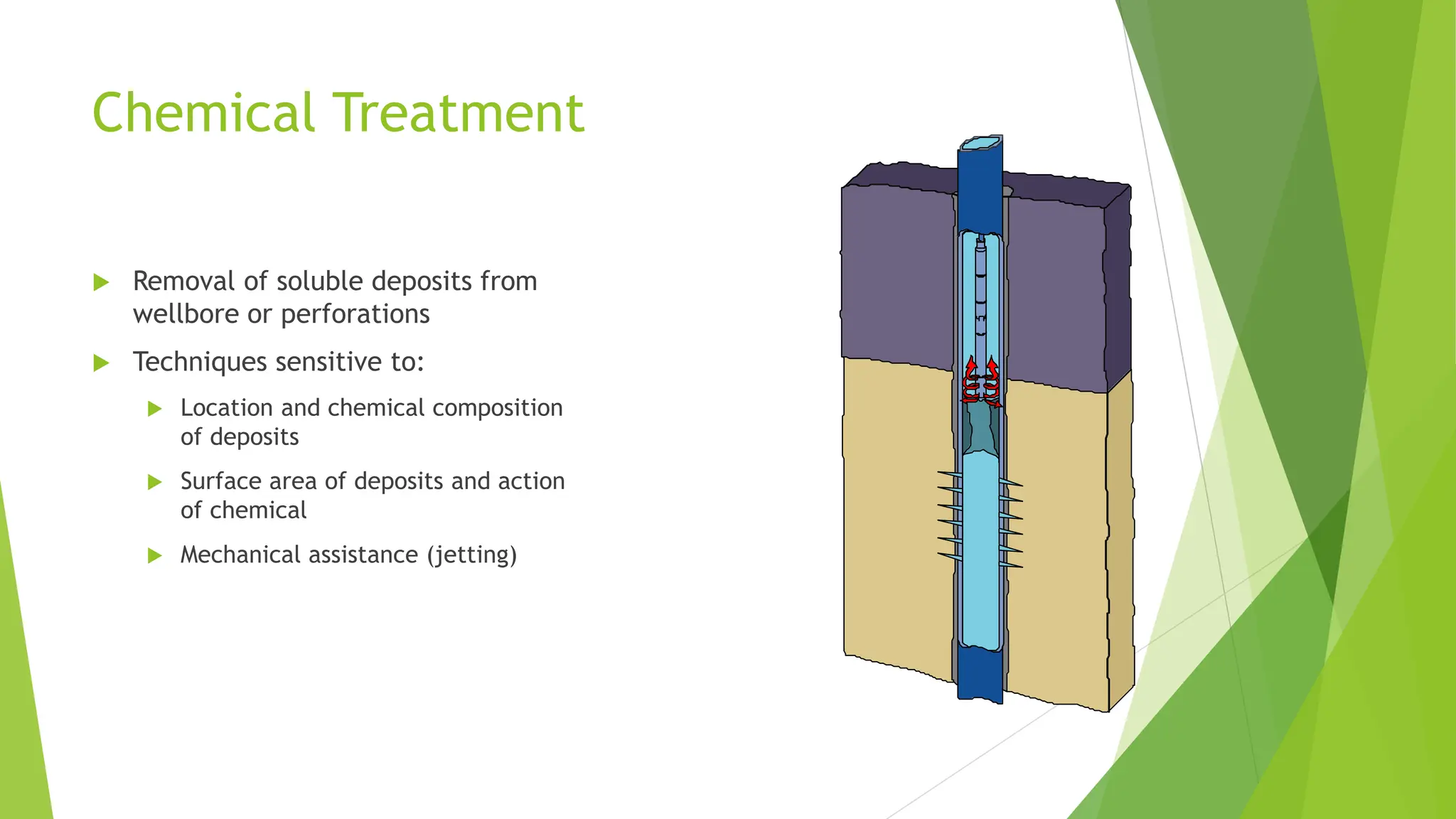
Chemical Treatment
Removalof soluble deposits from
wellbore or perforations
Techniques sensitive to:
Location and chemical composition
of deposits
Surface area of deposits and action
of chemical
Mechanical assistance (jetting)
57.
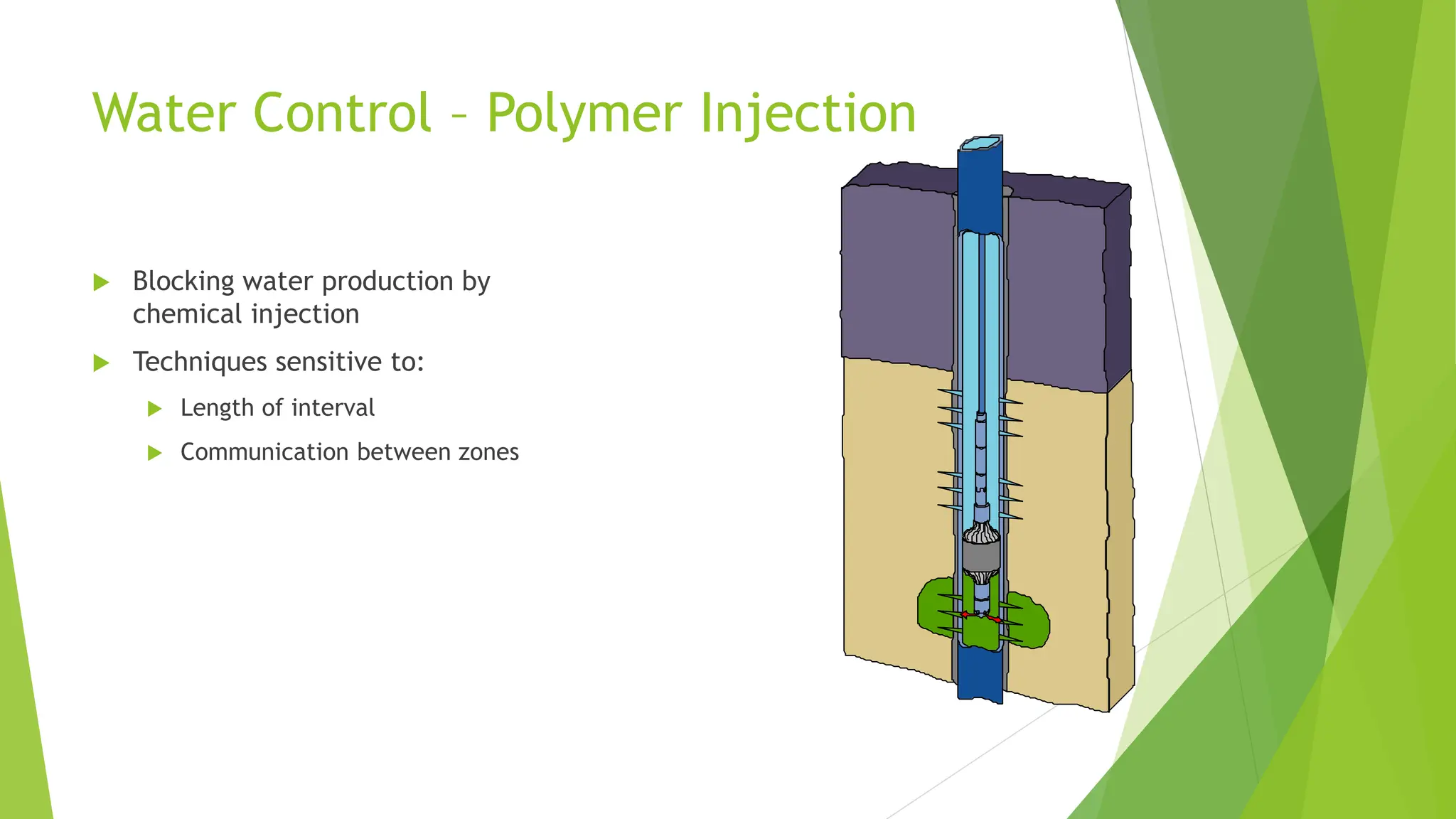
Water Control –Polymer Injection
Blocking water production by
chemical injection
Techniques sensitive to:
Length of interval
Communication between zones
58.
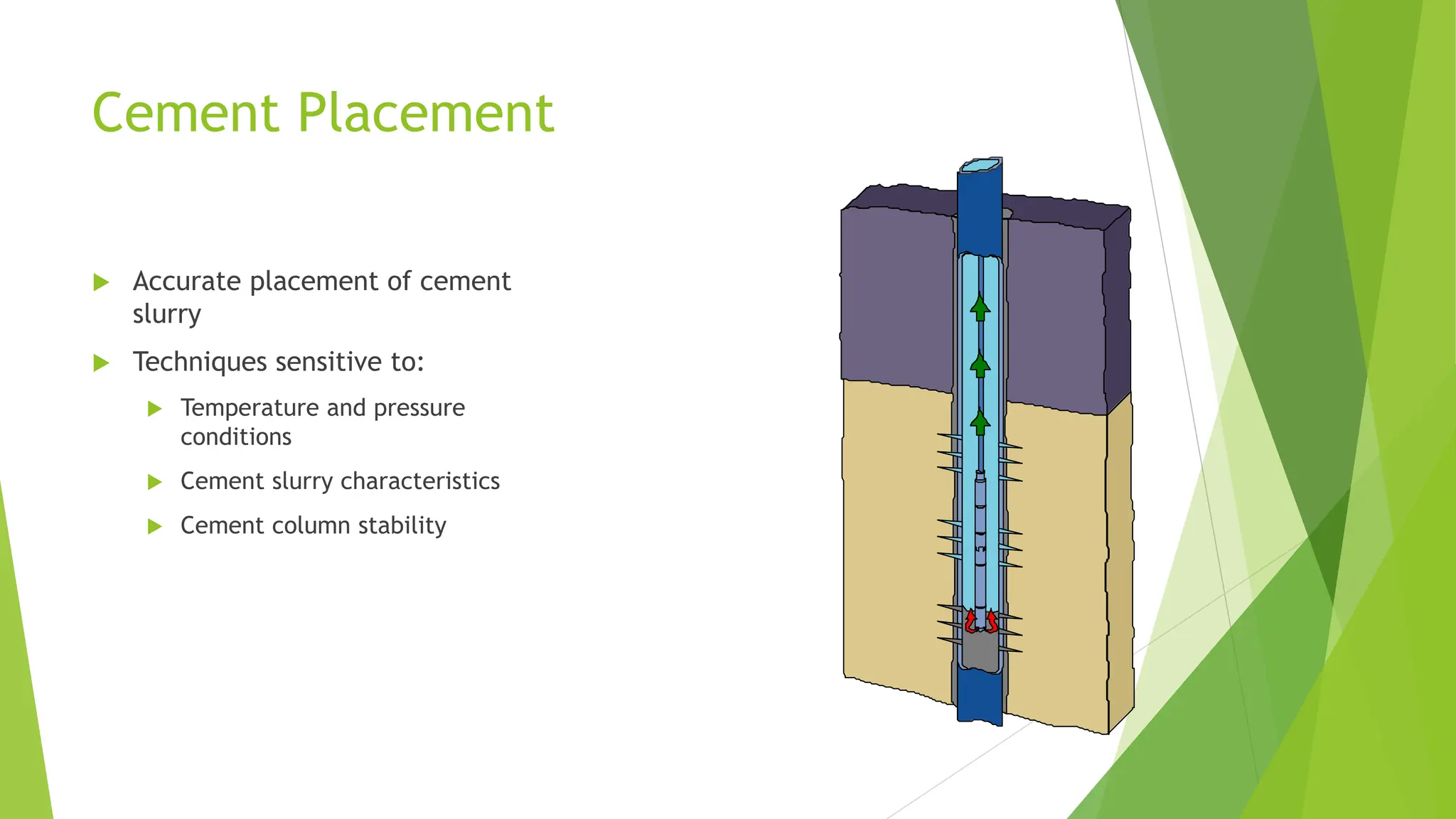
Cement Placement
Accurateplacement of cement
slurry
Techniques sensitive to:
Temperature and pressure
conditions
Cement slurry characteristics
Cement column stability
59.
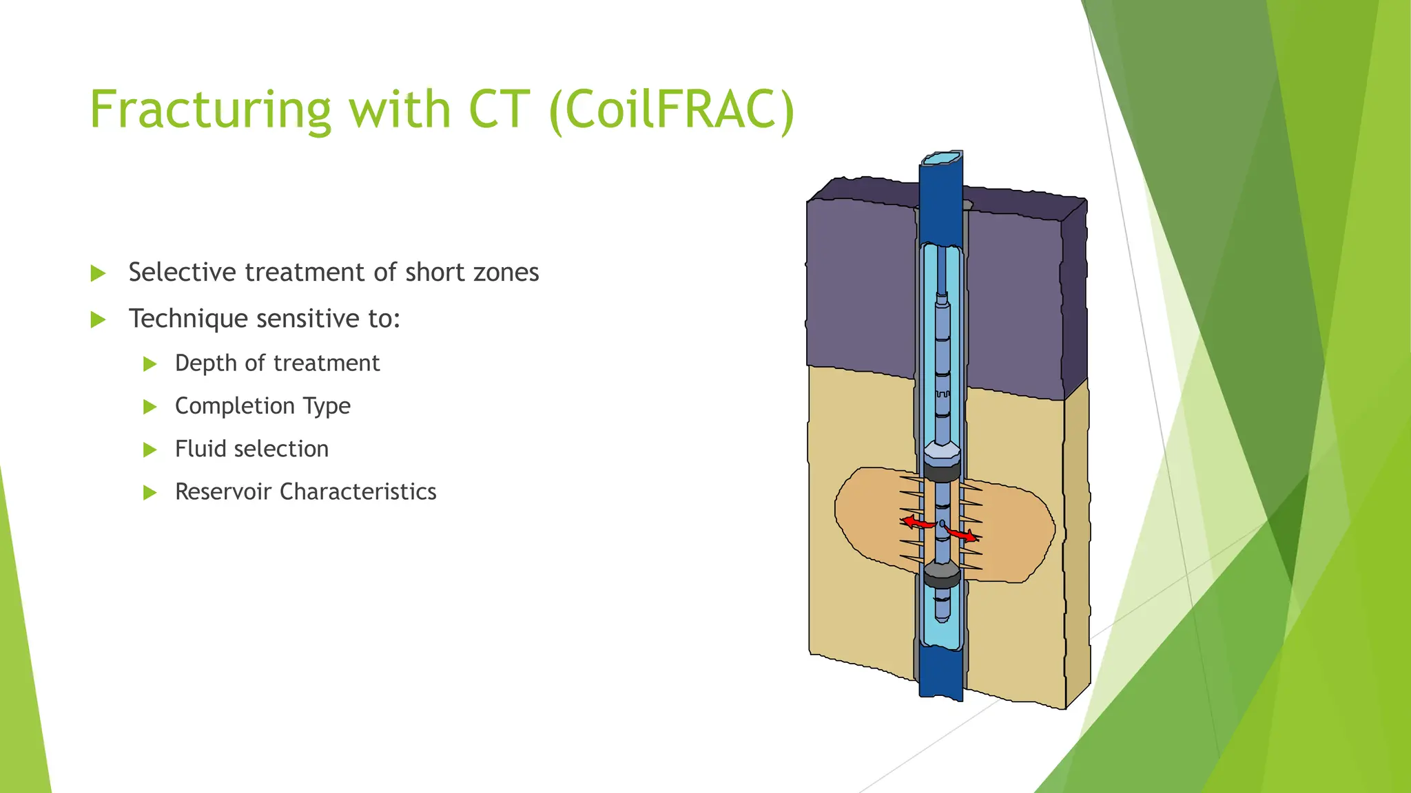
Fracturing with CT(CoilFRAC)
Selective treatment of short zones
Technique sensitive to:
Depth of treatment
Completion Type
Fluid selection
Reservoir Characteristics
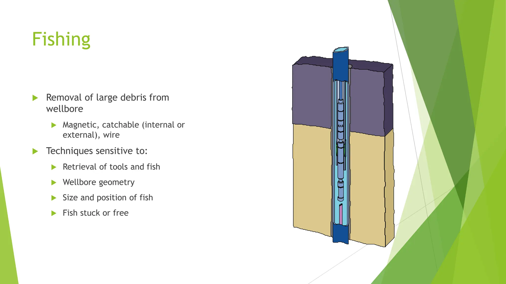
Fishing
Removal oflarge debris from
wellbore
Magnetic, catchable (internal or
external), wire
Techniques sensitive to:
Retrieval of tools and fish
Wellbore geometry
Size and position of fish
Fish stuck or free
66.
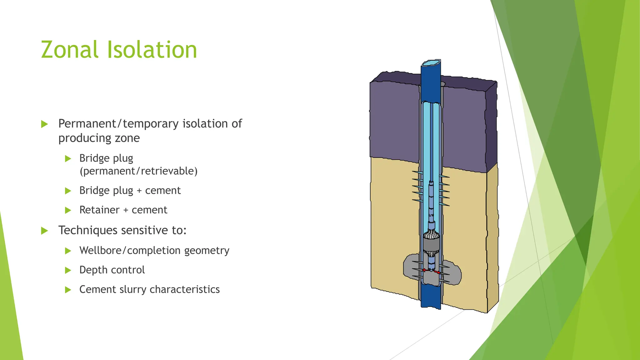
Zonal Isolation
Permanent/temporaryisolation of
producing zone
Bridge plug
(permanent/retrievable)
Bridge plug + cement
Retainer + cement
Techniques sensitive to:
Wellbore/completion geometry
Depth control
Cement slurry characteristics
67.
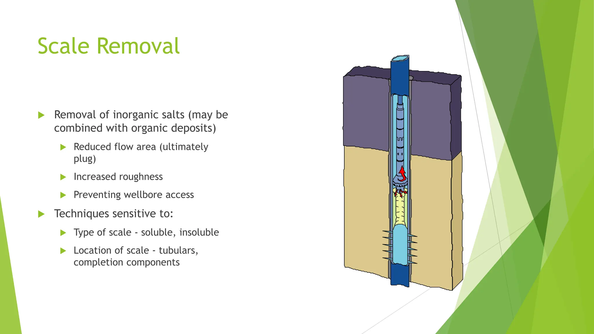
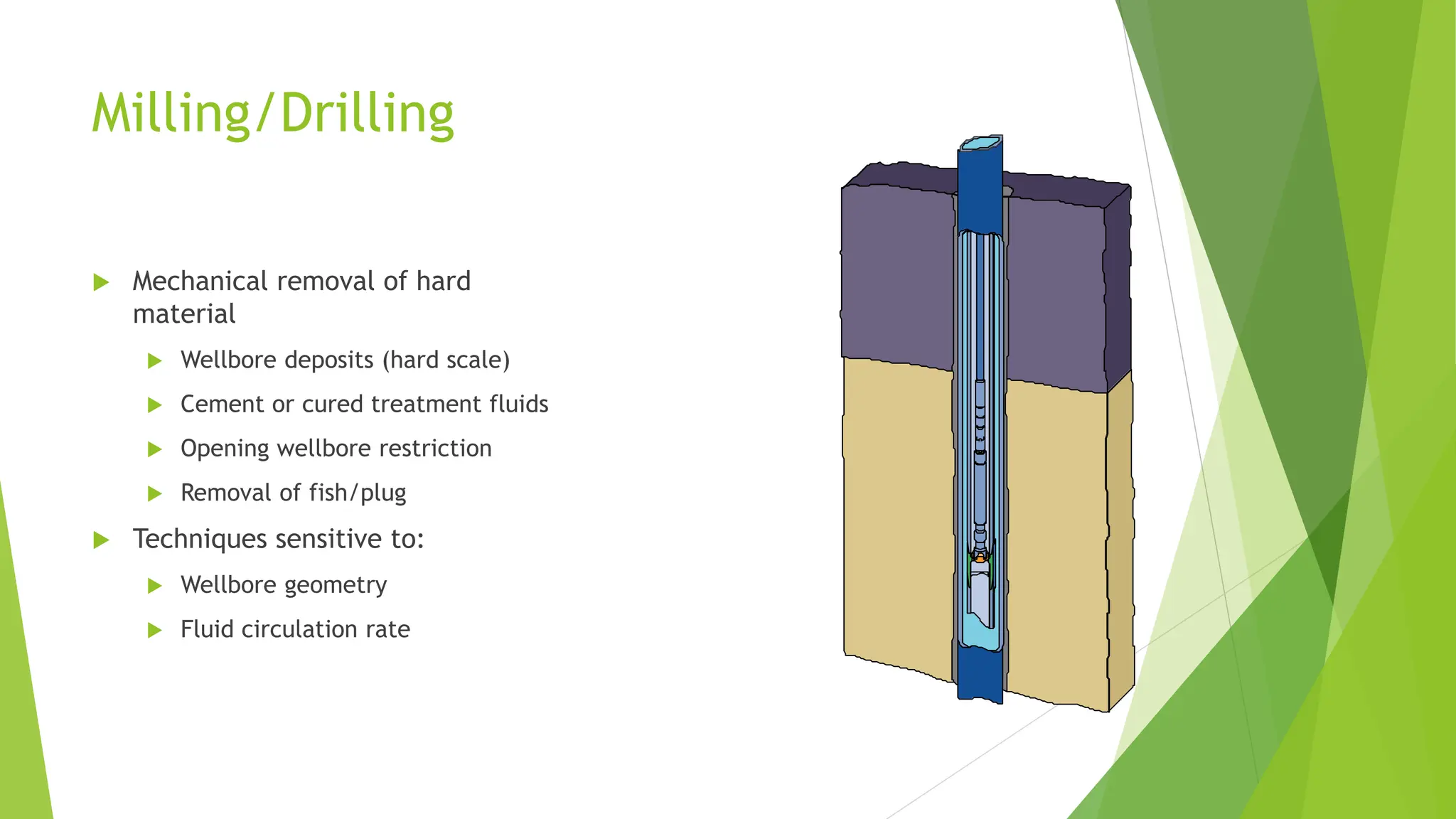
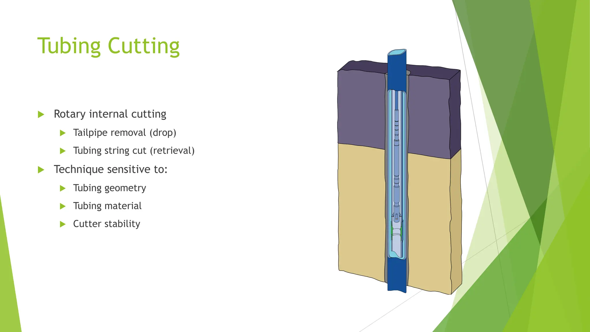
Milling/Drilling
Mechanical removalof hard
material
Wellbore deposits (hard scale)
Cement or cured treatment fluids
Opening wellbore restriction
Removal of fish/plug
Techniques sensitive to:
Wellbore geometry
Fluid circulation rate
68.
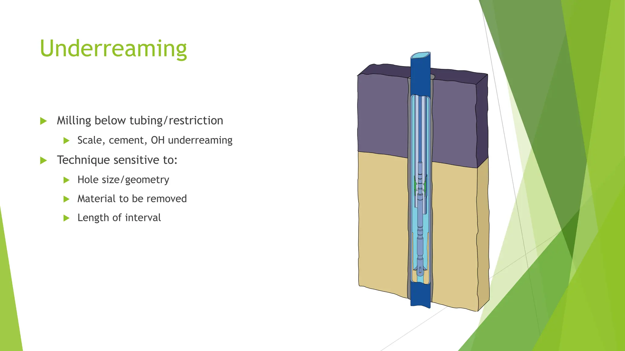
Underreaming
Milling belowtubing/restriction
Scale, cement, OH underreaming
Technique sensitive to:
Hole size/geometry
Material to be removed
Length of interval
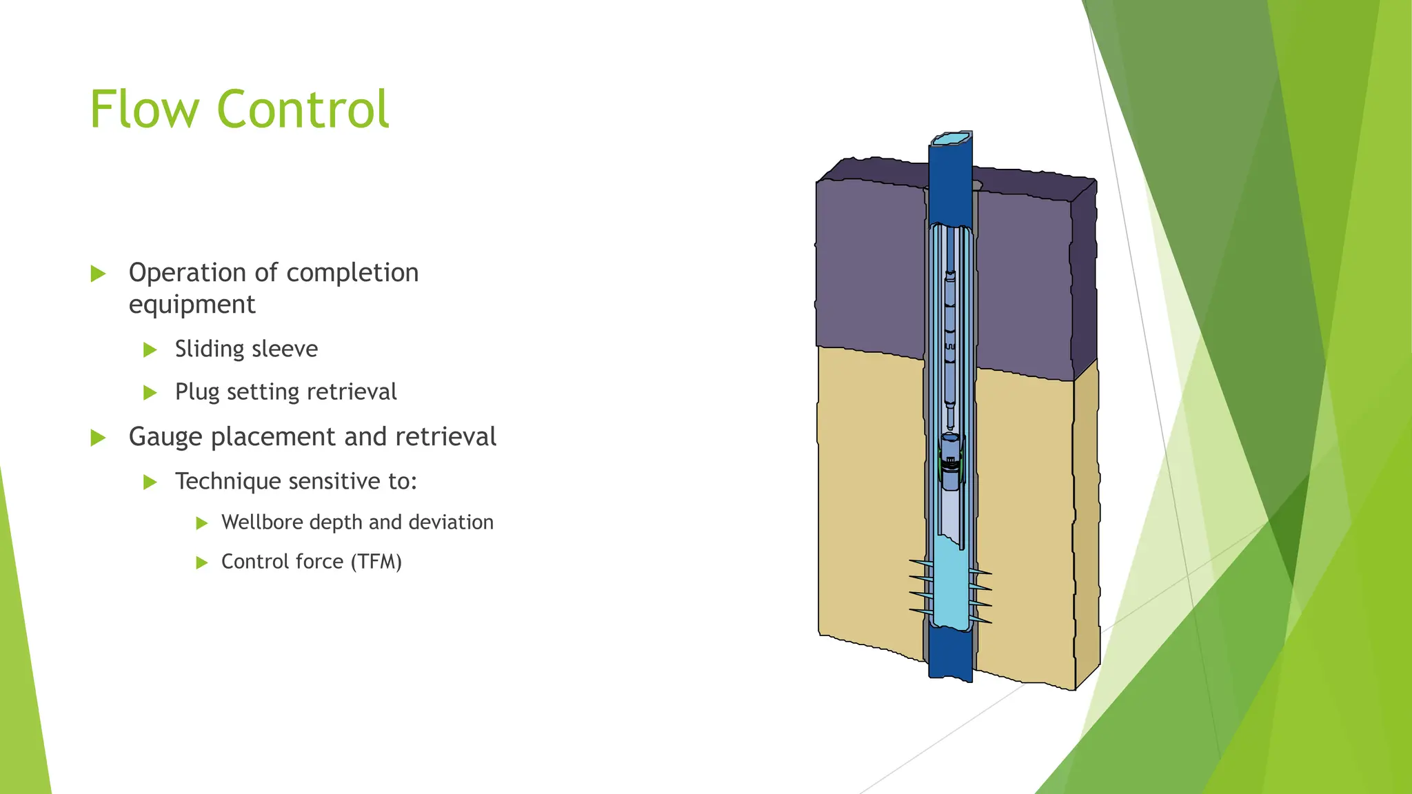
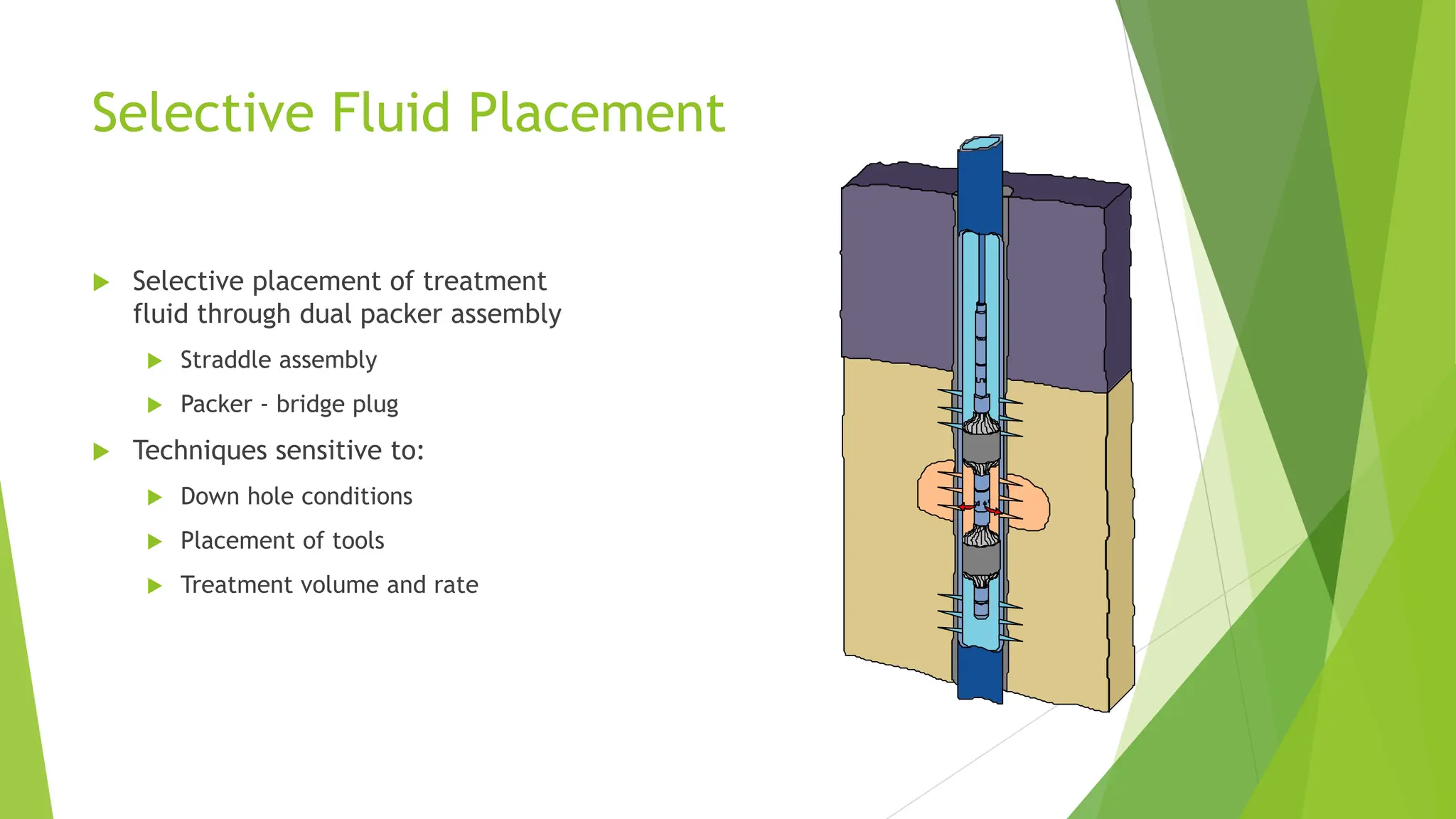
Selective Fluid Placement
Selective placement of treatment
fluid through dual packer assembly
Straddle assembly
Packer - bridge plug
Techniques sensitive to:
Down hole conditions
Placement of tools
Treatment volume and rate
71.
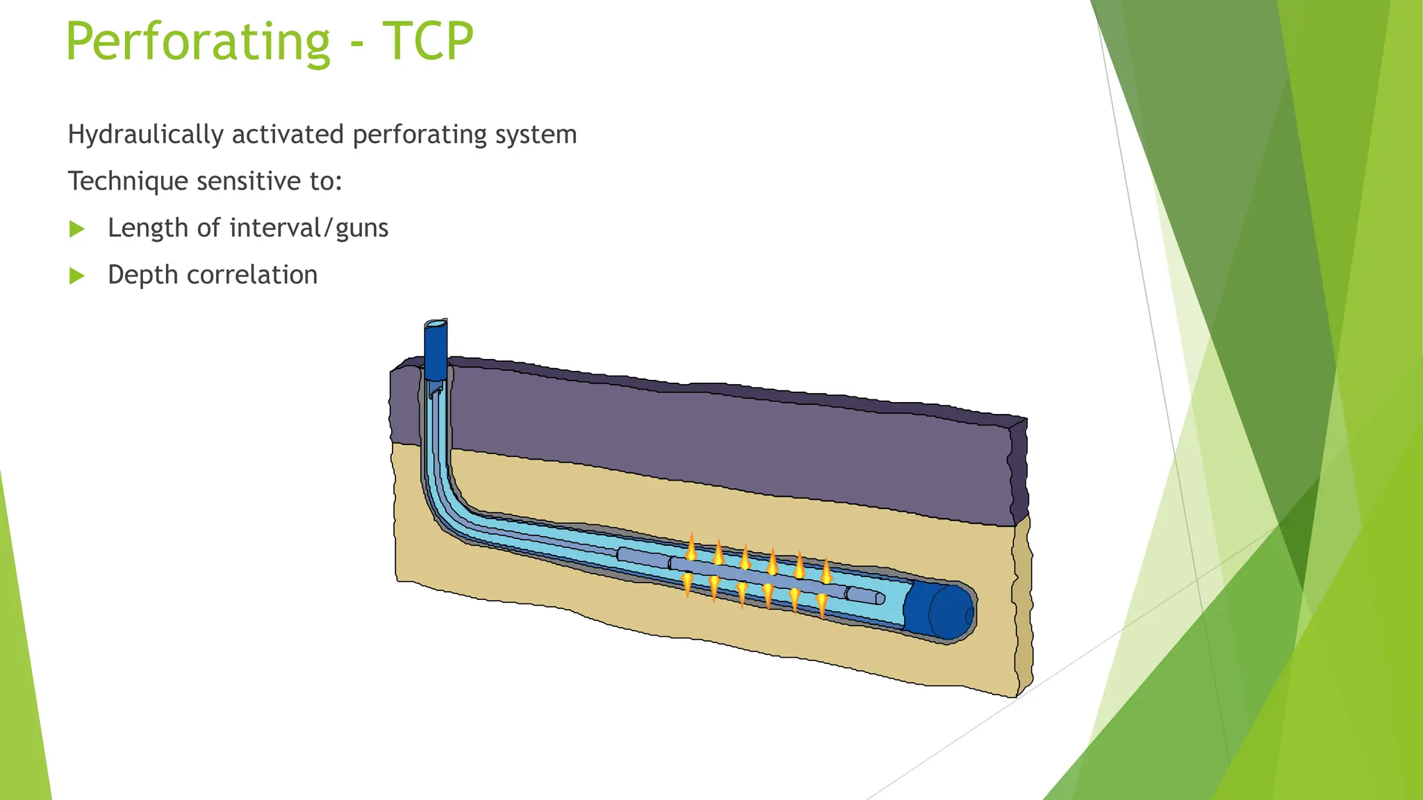
Perforating - TCP
Hydraulicallyactivated perforating system
Technique sensitive to:
Length of interval/guns
Depth correlation
72.
Production Logging -Memory
Wellbore and production data
recorded within toolstring
Pressure, temperature, flow rate
Techniques sensitive to:
Duration of survey/operation
Synchronization of time/depth
73.
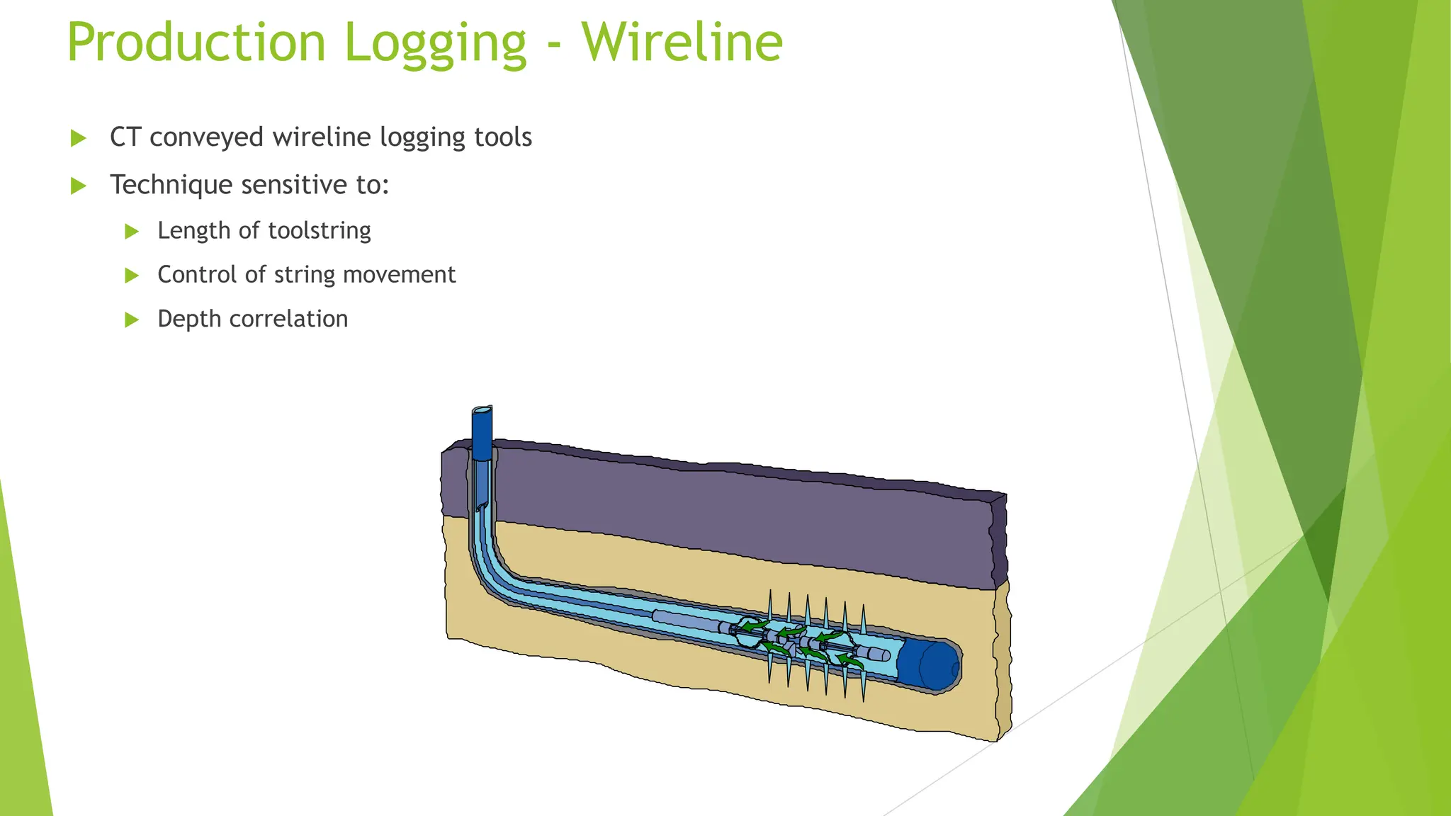
Production Logging -Wireline
CT conveyed wireline logging tools
Technique sensitive to:
Length of toolstring
Control of string movement
Depth correlation
74.
Perforating - Wireline
Electrically activated perforating system
Technique sensitive to:
Length of interval/guns
Depth correlation