Download as PDF, PPTX

![Telemetry with CT
9
Telemetry = tele [remote] + metron [measure]
Consider the drivers
Evolution of wells and reservoirs
Maturing reservoirs
Unconventional reservoirs
Deep water
More intelligent completions](https://image.slidesharecdn.com/silviulivescu-190821150055/85/Silviu-Livescu-9-320.jpg)
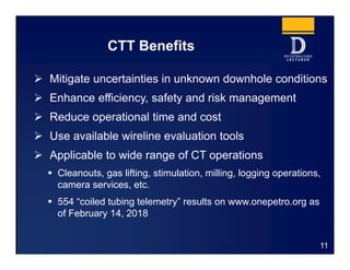
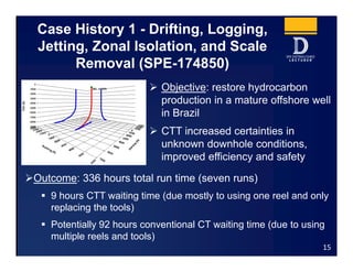
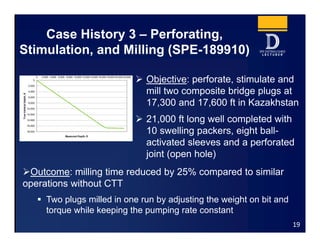
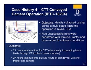
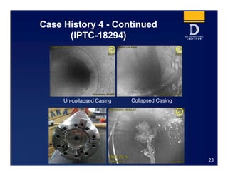
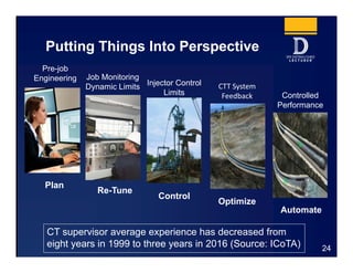
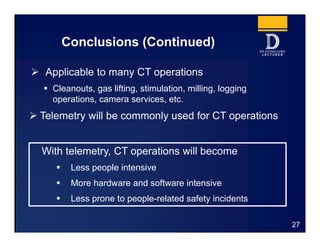

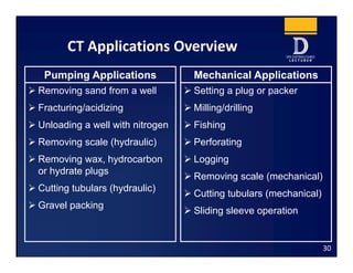
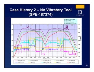

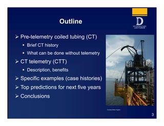
The document discusses coiled tubing telemetry (CTT) technology. It provides an overview of CTT, including its description and benefits. It also presents four case histories that demonstrate how CTT improved coiled tubing operations by enabling real-time downhole data acquisition. CTT allowed operations to be completed more efficiently and safely by mitigating uncertainties in unknown downhole conditions. The case histories show that CTT can reduce operational time and costs for applications like logging, milling, perforating and camera runs. The document concludes that CTT will become commonly used for coiled tubing operations to make them less people intensive and more automated.


