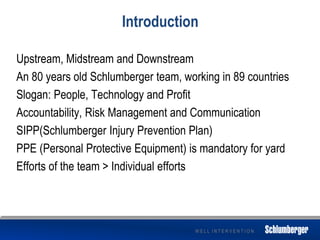
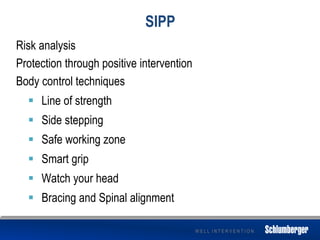
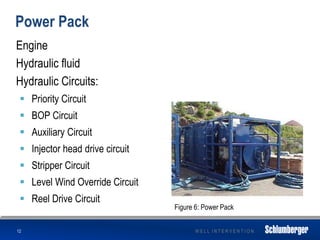
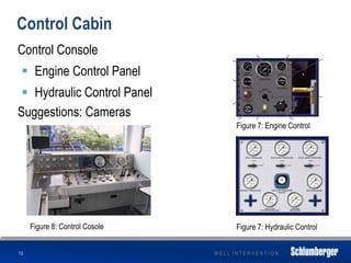
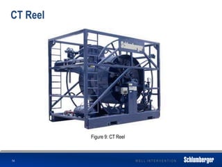
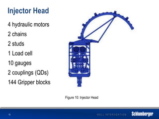
This presentation summarizes Schlumberger's well intervention process using coiled tubing units. It discusses Schlumberger's safety plan and techniques for injury prevention. It then provides an overview of the coiled tubing unit components including the power pack, control cabin, coiled tubing reel, injector head, and pressure control equipment. It also briefly discusses fluid and tool conveyance applications of coiled tubing as well as other learnings around pumping systems and inventory management. The presentation aims to provide a high-level overview of Schlumberger's well intervention process with coiled tubing.
A summary presentation of a 7" Liner job, demonstrating different components, mechanisms of liner hanger and other string components. Then a quick hint about cementing operation and some extra components involved in the job like the Handling equipment, VAM HT, ...etc.
Wellhead equipment Introduction Based on API 6a & NACEAmir Rafati
1. Typical Onshore Wellhead and Casing Head Types
• CSG HEAD NO.1
• CSG HEAD NO.3
• CSG HEAD NO.6
• CSG HEAD NO.8
• CSG HEAD NO.9
• CSG HEAD DESIGN DUE TO FIELD EXPERIENCES
• AG(H)-10K
• B(H)-10K
• C(H)-5K
• V(H)-5K
• T(H)-3K,5K
• WELLHEAD DESIGN DUE TO FIELD EXPERIENCES
2. Brief Description of Wellhead Equipment and their Types
• Sealings and Ring Gaskets
• Safety valves
• Gate valves
• Double Studded Adaptors
• Spools
• Hangers
• Flanges
3. Install and Testing Wellhead and Casing Head Equipment
• Safety valves
• Gate valves
• Double Studded Adaptors
• Spools
• Hangers
• Flanges
4. Introduction to API 6A applications
• PSL: PRODUCT SPECIFICATION LEVELS
• PR: PERFORMANCE REQUIREMENT
• T/C: TEMPERATURE CLASS
• M/C: MATERIAL CLASS
Tubing Landing nipples in petroleum industryPE Mahmoud Jad
Tubing Landing nipples in petroleum industry
# A completion component fabricated as a short section of tubular pipe with a machined internal surface that provides a seal area and a locking profile.
# Uses : 1) Plugging the tubing for: pressure testing
2) Installing flow control equipment such as: down chokes,regulators, SSVs, etc.
# Tubing Landing nipples types:
A) Seating nipple
1.Non-selective nipple (No-go landing nipple)
i. Top no go nipple
ii. Bottom no go nipple
2. Selective nipple
B) Hydraulic Landing Nipples
Decommissioning & Abandonment For Oil & Gasprada2000
Decommissioning & Abandonment for Oil & Gas Industry. This is a strategic Global Business Conference aimed at reducing the costs to decommission using latest technologies and strategies to limit the liabilities of Oil and Gas operators. It will give tools to deal with Legal disputes and environmental treaties.
Energy losses in Bends, loss coefficient related to velocity head.Pelton Whee...Salman Jailani
In this slide you learn the how to make the lablayout and the study the Energy losses, Pelton Wheel. Kaplan TURBINE, Franices TURBine And its Efficiency of Mecahanical Power Plants..
00923006902338
This lifting machine is used to carry heavy industrial machinery like lathe from one floor to another. We have analysed the strength and the capacity of this machine. We have checked critical points for failure and suggested design recommendations to increase the capacity to 3 tonnes from the present value of 1.1 tonne.
Team members: Ahsen, Ankit, Ankit, Shivam, Anurag, Deepak
Design and Analysis of Hydraulic Actuator in a Typical Aerospace vehicle | J4...Journal For Research
An Aerospace Vehicle is capable of flight both within and outside the sensible atmosphere. An Actuation System is one of the most important Systems of an Aerospace vehicle. This paper study involves detailed study of various controls Actuation System and Design of a typical Hydraulic Actuation Systems. An actuator control system concerned with electrical, electronic or electro mechanical. Actuator control systems may take the form of extremely simple, manually-operated start-and-stop stations, or sophisticated, programmable computer systems. Hydraulic Actuation System contains Electro Hydraulic Actuators, Servo Valves, Feedback Sensing elements, Pump Motor package, Hydraulic Reservoir, Accumulator, various safety valves, Filters etc. The main objective of this study involves design of Hydraulic Actuator and selection of various other components for the Actuation Systems of an Aerospace Vehicle. Design of the system includes design of Hydraulic actuator and also the Modeling and Analysis of actuator using sophisticated Software.
Performance Evaluation for Production of 5000kgHydraulic JackIOSR Journals
The report submitted presents detailed performance evaluation analysis for production of 5tonne
hydraulic jack. The main task is to produce it using two approaches namely conversional and reverse
engineering. Conversional design team were able to design the jack with all the necessary tolerance and limits,
those involve design calculations, producing standard drawing and cost analysis on each part involve. While
reverse engineering team were able to produce the jack through reverse engineering procedures and approach,
this involve selection of materials needed to produce the parts with our machines in the workshop, test analysis
for each component, assembling and testing to ensure effective performance
Experimental investigation of damping force of twin tube shock absorberIJERA Editor
A shock absorber is a mechanical device to damp shock impulse and convert kinetic energy into thermal energy. The damping effect of shock absorber depends on damping force and damping force is affected by various process parameters. In this analysis three process parameters damping diameter(A), number of holes(B) and suspension velocity(C) were considered and their effect on damping force of shock absorber was studied and accordingly suitable orthogonal array was selected by taguchi method. Experiment conducted on servo hydraulic testing machine and after conducting experiments damping force was measured and with the help of S/N ratio, ANOVA, Regression analysis optimum parameter values can be obtained and confirmation experiments was carried out. Twin tube shock absorber was used to carry out experimentation.
2. W E L L I N T E R V E N T I O N
Introduction
Upstream, Midstream and Downstream
An 80 years old Schlumberger team, working in 89 countries
Slogan: People, Technology and Profit
Accountability, Risk Management and Communication
SIPP(Schlumberger Injury Prevention Plan)
PPE (Personal Protective Equipment) is mandatory for yard
Efforts of the team > Individual efforts
3. W E L L I N T E R V E N T I O N
SIPP
Risk analysis
Protection through positive intervention
Body control techniques
Line of strength
Side stepping
Safe working zone
Smart grip
Watch your head
Bracing and Spinal alignment
4. W E L L I N T E R V E N T I O N
Brief geological summary
Oil formation
Layers of kerogen (shales)
Porosity and Permeability
Seismic Acquisition
Oil and gas exploration
Concept of Super saturation
Precipitation
Deposition of fill materials
4
Figure 2: Seismic Aquisition
Figure 1: Shale
5. W E L L I N T E R V E N T I O N
Well: Bird’s eye view
5
Reservoir hunt
Drilling
Open well logging
Cementing
Well completion
Production Tubing
Christmas Tree
Rig up
Underground blasting
Figure 3: Pictorial view
6. W E L L I N T E R V E N T I O N
Treating Equipment
Color distinction
Low pressure equipment
Various types of hoses
Unions
Butterfly valves
High pressure equipment
Adaptors:
Used to join one type of connection to another connection
Flange connection:
To connect a wellhead
6
7. W E L L I N T E R V E N T I O N
Cont.
2-in loop connection:
A combination of two Chiksans
Chiksan swivel joint:
To absorb shock and for flexibility
2-way (for changing direction)
3-way (for changing elevation)
Check valve:
One directional flow
Plug valve:
To control pressure on high pressure lines
8. W E L L I N T E R V E N T I O N
Coiled Tubing
Brief history
Premier functions
( Fill material = Unhappy Client = Unhappy you)
Advantages over other technologies
Highly deviated and horizontal wells
Ability to pull and push
Fluid and Tool Conveyance
Almost any job can be done with CT
8
Figure 4: Scaled-up Tubing
9. W E L L I N T E R V E N T I O N
Fluid Conveyance
Nitrogen Kickoff
Hydrostatic pressure difference maintenance
Fill Removal
Fluids to clean out the fill material
Cement Placement
Reduction of slurry contamination, accurate placement
Stimulation
Improving permeability
9
10. W E L L I N T E R V E N T I O N
Tools Conveyance
Coiled tubing fishing and milling
Advantages of using CT
Downhole valve manipulation
To control the flow from various zones
Blasting Services
Acid washes, scale removal etc.
Zonal Isolation
Separation of zones via packers and plugs
CT logging
Real time data for analysis
CT Drilling
10
11. W E L L I N T E R V E N T I O N
Coiled Tubing Unit (CTU)
Offshore and Onshore
3 piece and 4 piece
11
Figure 5: Coiled Tubing Unit
12. W E L L I N T E R V E N T I O N
Power Pack
Engine
Hydraulic fluid
Hydraulic Circuits:
Priority Circuit
BOP Circuit
Auxiliary Circuit
Injector head drive circuit
Stripper Circuit
Level Wind Override Circuit
Reel Drive Circuit
12
Figure 6: Power Pack
13. W E L L I N T E R V E N T I O N
Control Cabin
Control Console
Engine Control Panel
Hydraulic Control Panel
Suggestions: Cameras
13
Figure 7: Engine Control
Figure 7: Hydraulic ControlFigure 8: Control Cosole
14. W E L L I N T E R V E N T I O N
CT Reel
14
Figure 9: CT Reel
15. W E L L I N T E R V E N T I O N
Injector Head
4 hydraulic motors
2 chains
2 studs
1 Load cell
10 gauges
2 couplings (QDs)
144 Gripper blocks
15
Figure 10: Injector Head
16. W E L L I N T E R V E N T I O N
Pressure Control Equipment
Stripper
BOP
16
Figure 11: Stripper and BOP
17. W E L L I N T E R V E N T I O N
Miscellaneous Learning
STEM
Inventory
C-Pump
Triplex pump
17
Figure 13: Triplex pump
Figure 12: Centrifugal pump