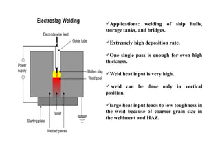
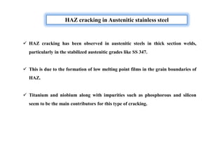
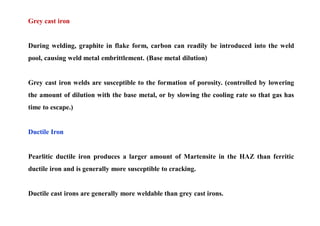
This document discusses various topics related to welding metallurgy including:
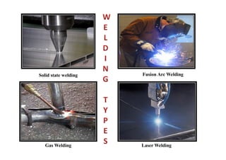
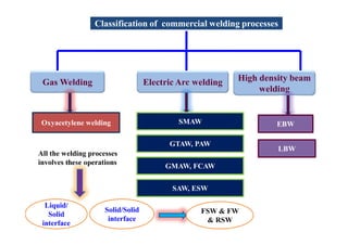
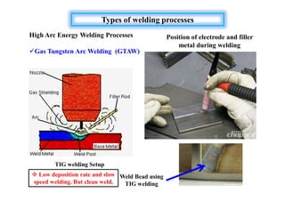
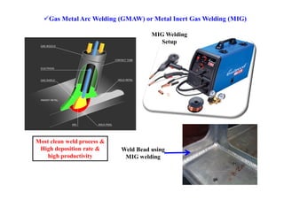
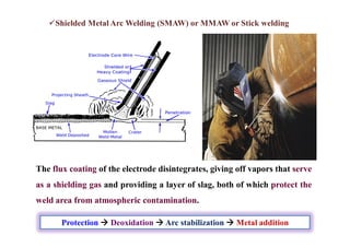
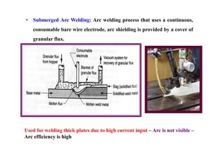
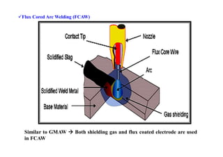
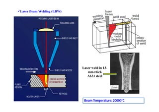
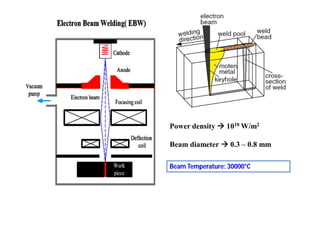
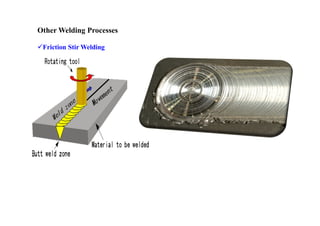
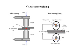
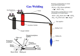
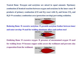
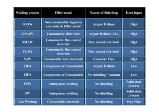
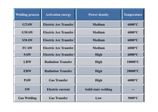
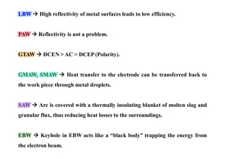
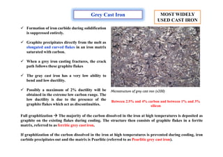
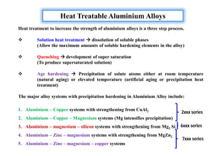
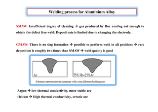
- The classification of commercial welding processes such as gas welding, arc welding, and high density beam welding.
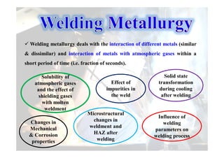
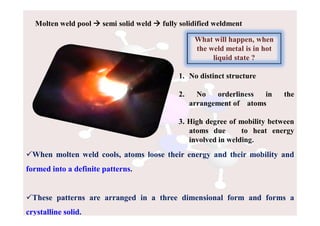
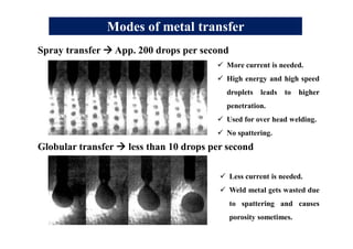
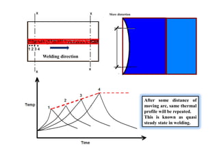
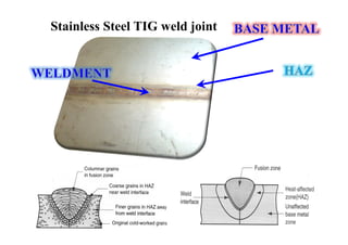
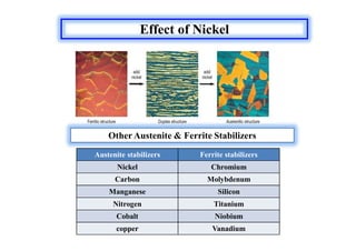
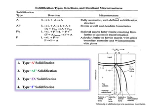
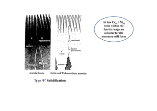
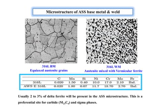
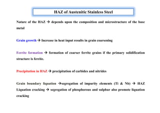
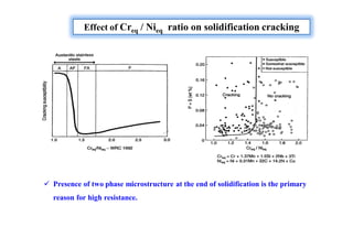
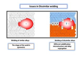
- How the microstructure of metals changes during the welding process as the weld metal transitions from liquid to solid states.
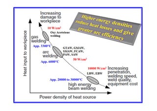
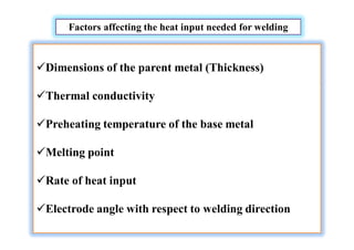
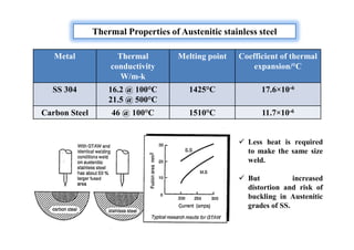
- Factors that influence the heat input required for welding like material thickness, thermal conductivity, and preheating temperature.
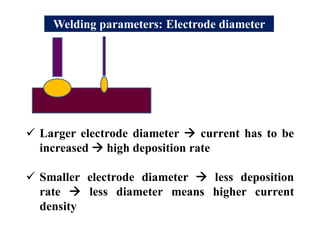
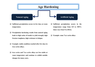
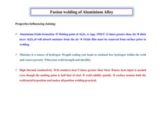
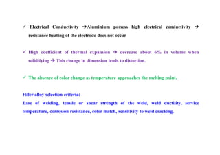
- Different welding parameters like current, voltage, speed, and electrode diameter and how they affect the weld bead.
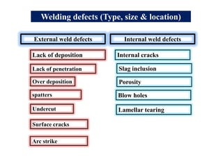
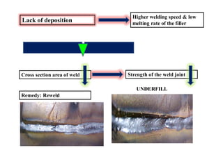
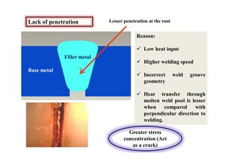
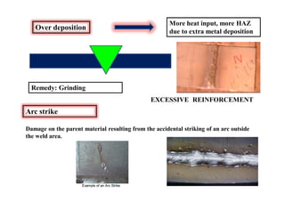
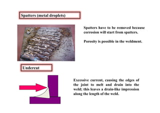
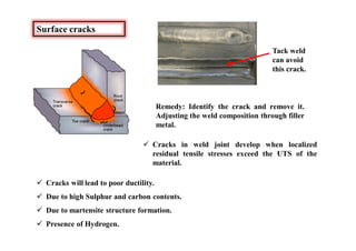
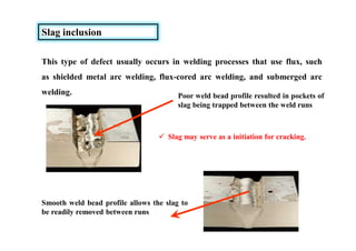
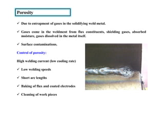
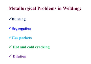
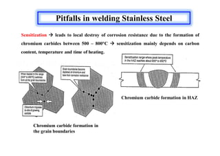
- Common weld defects such as lack of penetration, porosity, cracks and how to prevent them.
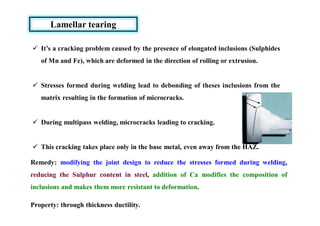
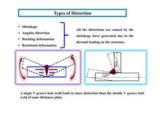
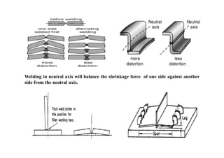
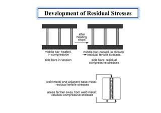
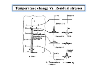
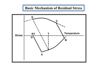
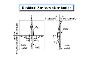
- How residual stresses are induced during welding
![Efficiency in welding and Heat input:
Where ,
Q = Heat transfer rate from the heat source to the work piece
Qnominal = Nominal power of the heat source
Always efficiency is less than one [η˂1] due to the lose of heat to the
surroundings during welding.
Where, E = Arc voltage; I = welding current and V = Welding speed
Heat input per unit length of the
weld
Q = EI/V](https://image.slidesharecdn.com/weldingtechnologybya-170922101945/85/Welding-technology-by-A-Vinoth-Jebaraj-25-320.jpg)
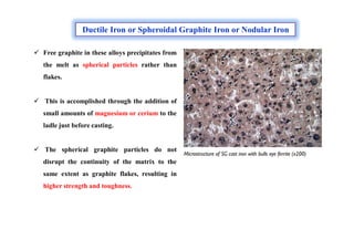
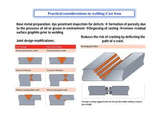
![Welding parameters: Welding Current [I]
Current heat Melting rate
Deposition rate
(Amount of filler
metal deposited)
Fusion zone
(Increasing the
penetrating power)
Increasing current will
lead to more effect on the
fusion zone penetration](https://image.slidesharecdn.com/weldingtechnologybya-170922101945/85/Welding-technology-by-A-Vinoth-Jebaraj-27-320.jpg)
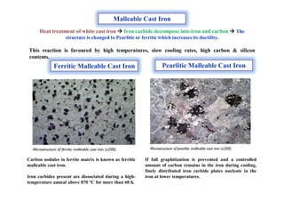
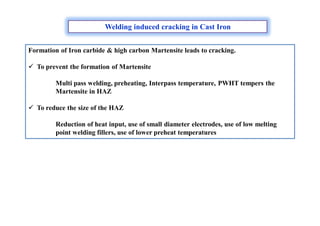
![Welding parameters: Arc voltage [v]
Arc voltage α Arc length
Arc voltage
Arc length
Bead width
If arc length increases or decreases too much then arc becomes unstable.
L1
L2](https://image.slidesharecdn.com/weldingtechnologybya-170922101945/85/Welding-technology-by-A-Vinoth-Jebaraj-28-320.jpg)
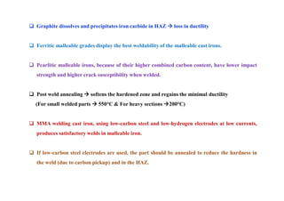
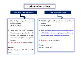
![Welding parameters: Speed [s]
0.5 m/min
1.0 m/min
Welding speed
Decrease in penetration
Increase in bead width
Molten metal
has low
thermal
conductivity
High productivity,
less heat input, less
distortion and
residual stress](https://image.slidesharecdn.com/weldingtechnologybya-170922101945/85/Welding-technology-by-A-Vinoth-Jebaraj-29-320.jpg)

![Why Dissimilar welding is needed?
[For process system operate at different service conditions]
More resistible to
corrosion
More easy to process
and inexpensive
Wrought
structure
Wrought
structure
Cast structure](https://image.slidesharecdn.com/weldingtechnologybya-170922101945/85/Welding-technology-by-A-Vinoth-Jebaraj-113-320.jpg)
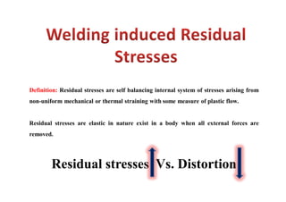
![Types of Residual Stresses
They are commonly classified into two groups:
Macro Residual stresses (Residual stresses of the first kind)
[Measured over a gauge length that encompasses several grains]
Micro Residual stresses (Residual stresses of the second kind)
[Measured within a single grain or a particular set of grains
Both types can contributing SCC or fatigue initiation depending upon the situation.](https://image.slidesharecdn.com/weldingtechnologybya-170922101945/85/Welding-technology-by-A-Vinoth-Jebaraj-136-320.jpg)
![Sources of Residual Stresses
Residual stresses owing to the shrinkage process of the Seam
and HAZ.
Residual stresses owing to the more rapid cooling of the surface
[quenching residual stresses]
Residual stresses owing to a phase transformation](https://image.slidesharecdn.com/weldingtechnologybya-170922101945/85/Welding-technology-by-A-Vinoth-Jebaraj-139-320.jpg)


