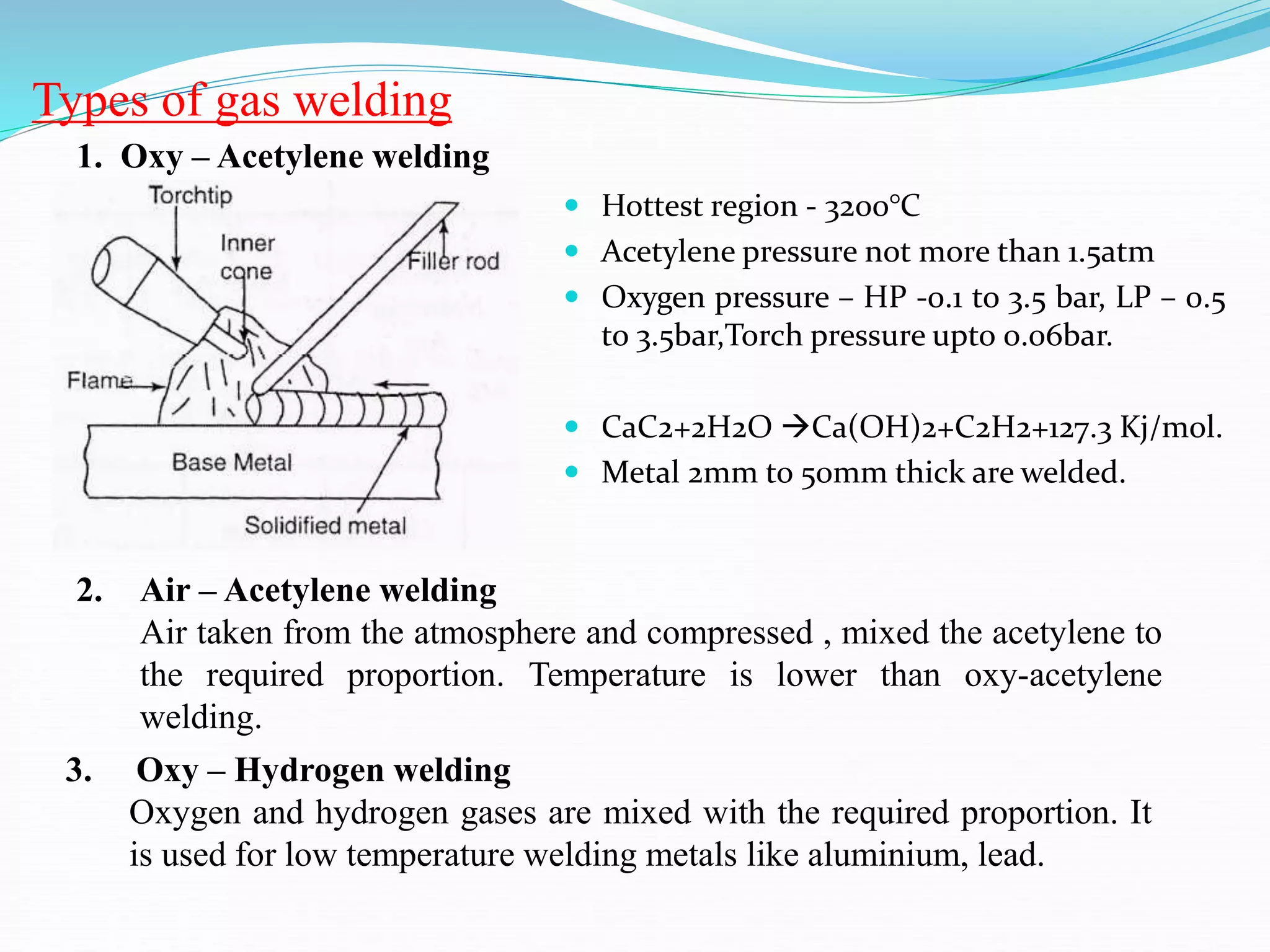
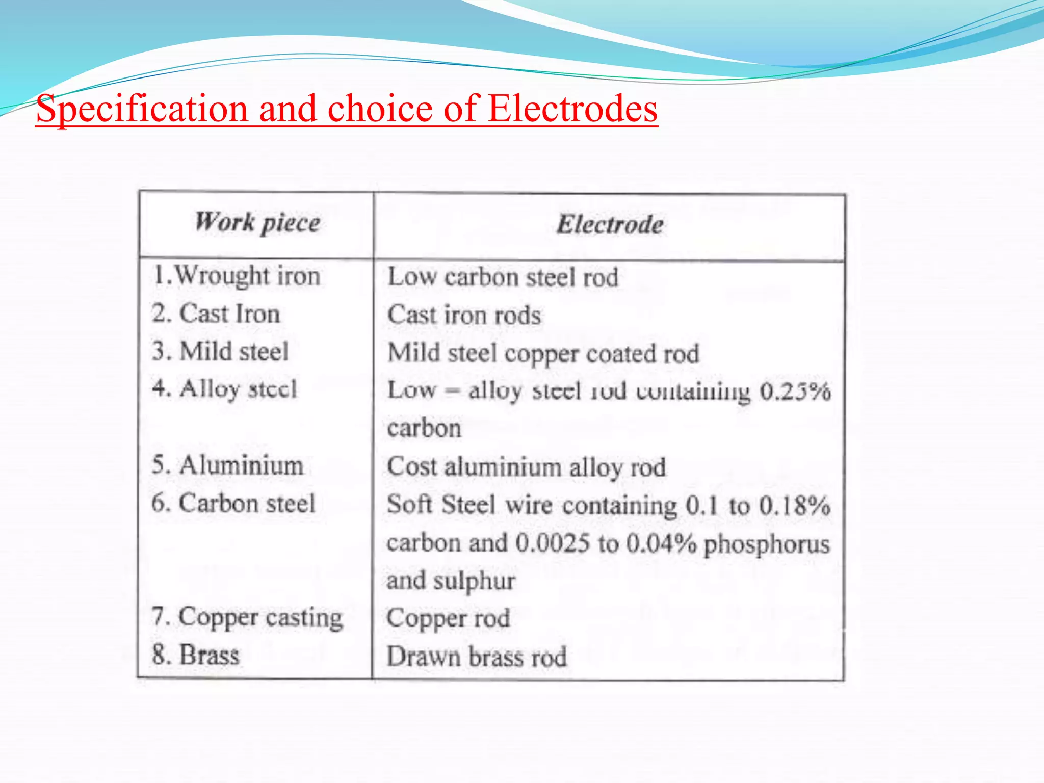
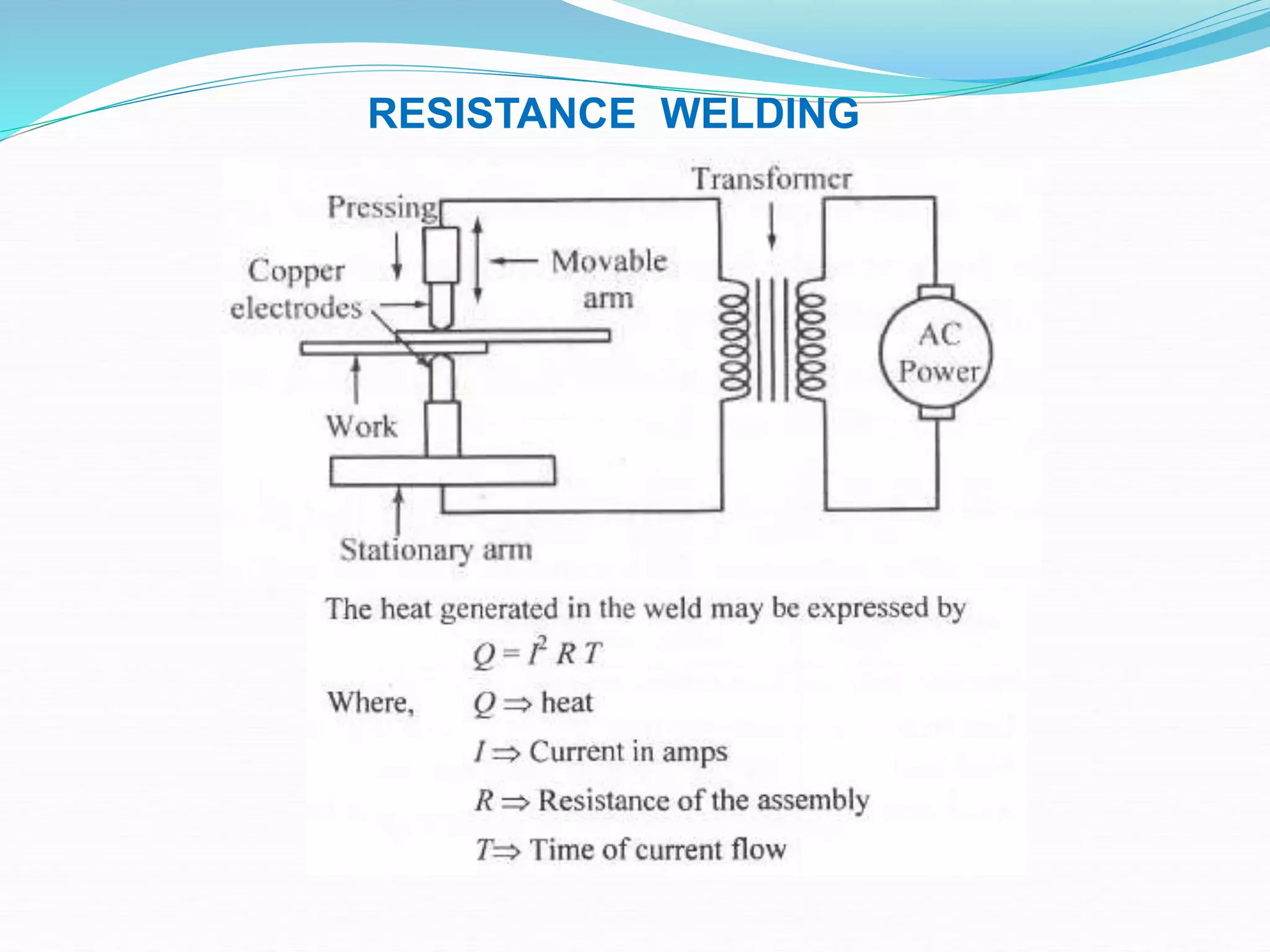
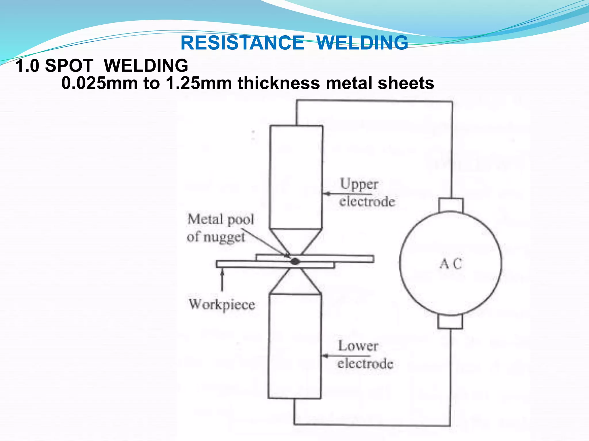
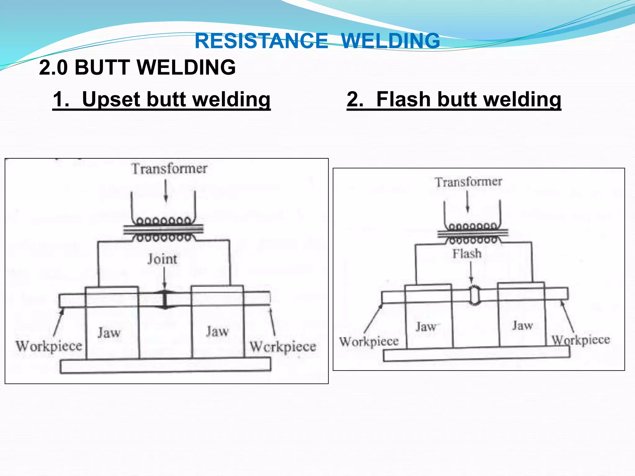
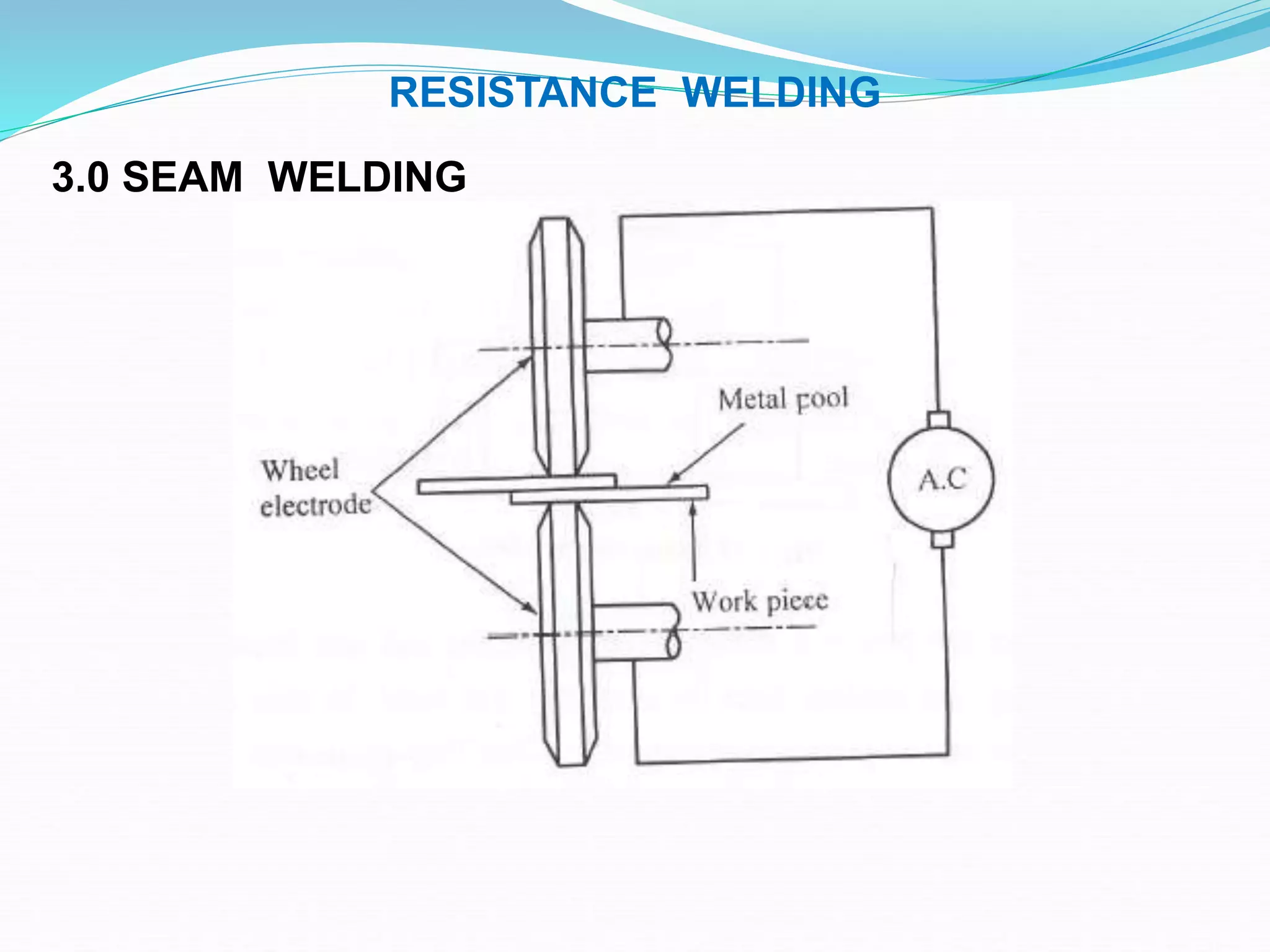
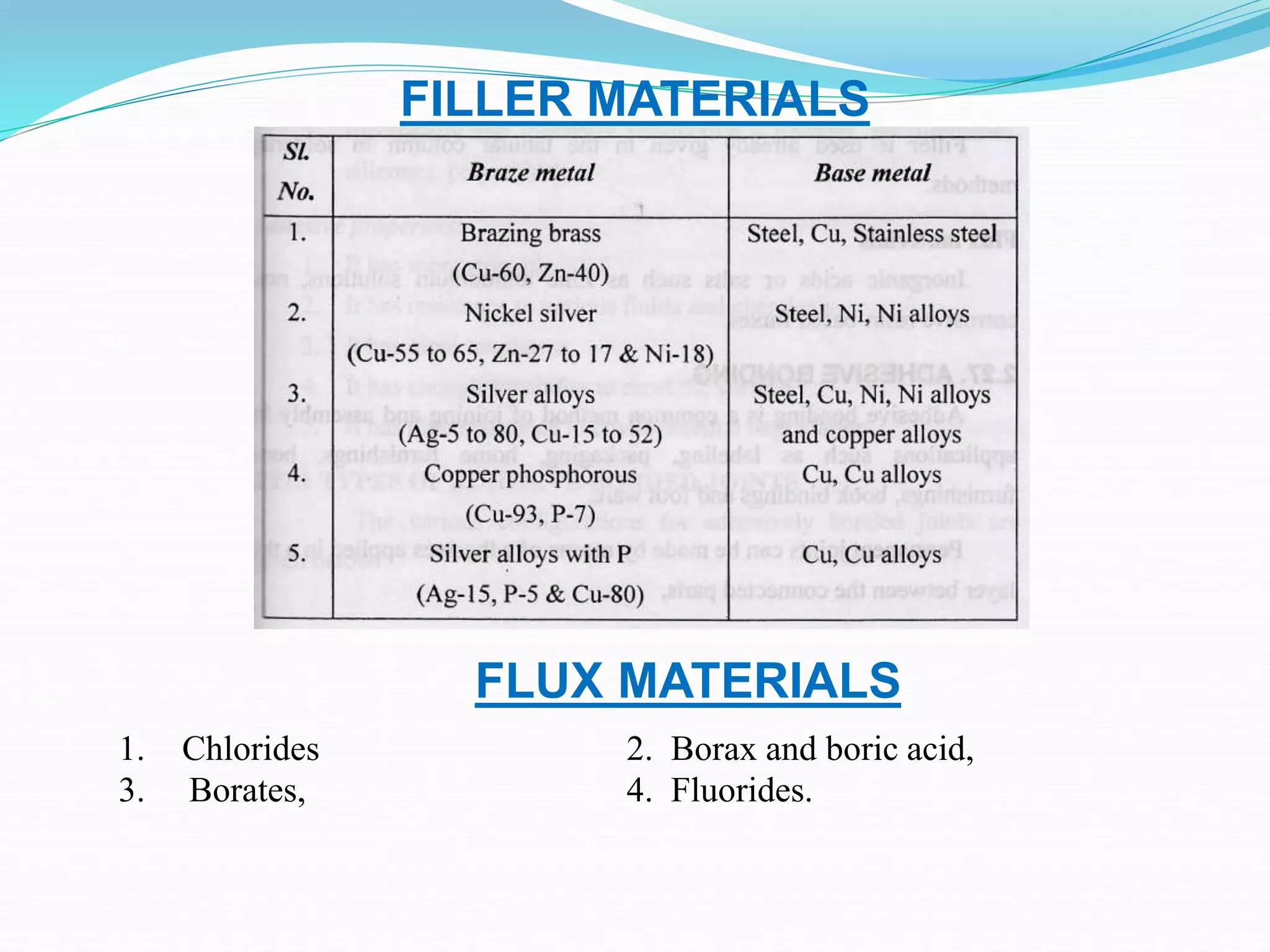
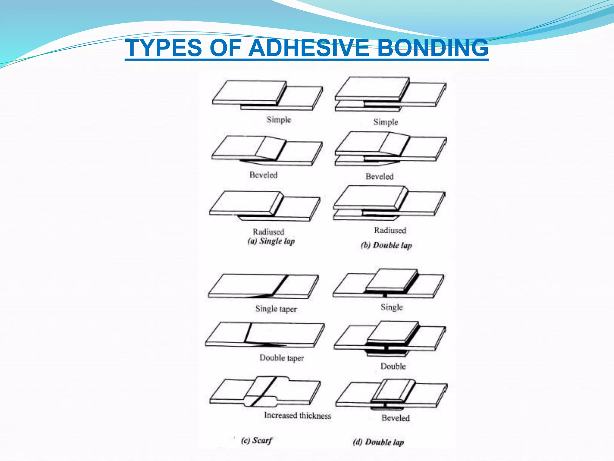
SlideShare a Scribd company logo
JOINING PROCESSES
Fusion welding processes – Types of Gas welding – Equipments used –
Flame characteristics – Filler and Flux materials - Arc welding equipments -
Electrodes – Coating and specifications – Principles of Resistance welding –
Spot/butt, seam welding – Percussion welding - Gas metal arc welding –
Flux cored – Submerged arc welding – Electro slag welding – TIG welding
– Principle and application of special welding processes - Plasma arc
welding – Thermit welding – Electron beam welding – Friction welding –
Diffusion welding – Weld defects – Brazing and soldering process –
Methods and process capabilities – Filler materials and fluxes – Types of
Adhesive bonding.
 INTRODUCTION:
 The process of joining similar metals by the application
of heat is called ‘Welding’.
 Welding can be obtained with or without application of
pressure and with or without addition filler metal, which
known as ‘ electrode’.
 During welding the edges of these metal pieces are either
melted or brought to the plastic condition.
 A good welded joint is as strong as the parent metal. It is
also used in various industries such as aircraft frame
works, railway wagons, furniture, automobile bodies,
ship building etc

Fusion welding
The metal at the joint is heated to a molten state and then it is
allowed to solidify. Pressure is not applied during the welding
process, it is also called as non pressure welding. E.g. – gas
welding , Arc welding, Thermit welding
The metal at the joint is heated to a plastic state and are pressed
together to make the joint. E.g. – Electric resistance welding,
Forge welding
Plastic welding
Types of gas welding
2. Air – Acetylene welding
Air taken from the atmosphere and compressed , mixed the acetylene to
the required proportion. Temperature is lower than oxy-acetylene
welding.
3. Oxy – Hydrogen welding
Oxygen and hydrogen gases are mixed with the required proportion. It
is used for low temperature welding metals like aluminium, lead.
1. Oxy – Acetylene welding
 Hottest region - 3200°C
 Acetylene pressure not more than 1.5atm
 Oxygen pressure – HP -0.1 to 3.5 bar, LP – 0.5
to 3.5bar,Torch pressure upto 0.06bar.
 CaC2+2H2O Ca(OH)2+C2H2+127.3 Kj/mol.
 Metal 2mm to 50mm thick are welded.
Gas Welding Equipments
Flame Characteristics
1. Neutral Flame
 Equal quantity of oxygen and acetylene.
 Inner cone develops heat to melt the metal.
 Outer cone are
Used for welding steel, cast iron, copper Al .
2. Carburising Flame  More acetylene than oxygen.
 Sharp Inner cone
 White intermediate cone called feather cone
 Bluish Outer cone
 Used for welding very low carbon steel,
monel metal, alloy steels, non ferrous
materials.
Flame Characteristics
3. Oxidising Flame
 More oxygen than acetylene.
 Smaller Inner cone
 Outer cone
 Used for welding brass and bronze.
 Gas welding Technique:
 In gas welding, the speed and quality of the welding can
be improved by the proper selection of torch size, filler
material, method of moving the torch along the weld and
the angle at which the torch is held
 Leftward or forward welding:
 This method allows the preheating of the plate
immediately ahead of the molten pool.
 The torch is very slight sideways movement.
 The rod should be moved faster without sideways
movement
 M.S plate up to 5mm thichness and cast iron and non-
ferrous metals
 Rightward or backward welding:
 The torch flame moves left to right.
 There is no sideways movement in this welding
 The torch held at an angle between 40 to 50to the plane
of the weld
 Welding rod is at 30 to 40. The welding speed is 20 to
25% higher and the fuel consumption is 15 to 25% lower
than rightward welding
 It provides a better shielding against atmospheric
reaction.
 Advantages:
 Temperature of flame can be easily controlled
 All types of metal can be weld
 The cost of equipment is less
 The flame can be used for welding and cutting
 It can be used in the factory of in the field
 Maintenance cost of gas welding equipment is less
 Disadvantages:
 It is not useful joining the thick plate
 It is a slow process
 Strength of weld is not so good as arc welding
 Handling and storing of gas cylinders need more car
 Gas flame takes up a longer time to heat up the metal
than an electric arc.
Gas Welding Technique
1. Leftward or Forward Welding
2. Rightward or Backward Welding
Arc Welding Equipment
Heat is developed by an electric arc
Specification and choice of Electrodes
 Electrode types:
 (i) Consumable electrode and
 (ii) Non-Consumables electrode
 Consumable electrode:
 The Consumable electrode is not only used to produce
arc between work and electrode but also provides filler
material during welding
 These may be made of various metals depending upon
their purpose and the chemical composition of the
metals to be welded.
 1. Bare electrodes 2. Lightly coated electrode
 3. Heavily coated electrode.
 Bare electrodes: do not have any coating of flux on their
surface.
 They must be used only straight polarity
 Bare electrode are used, the molten metal reacts with the
atmosphere
 This causes defects in the weld
 Used in the submerged arc welding and inert gas
welding.
 Lightly coated electrodes: have a coating layer of several
tenths of a millimeter and is 1 to 5% of the electrode wt.
 Main purpose of light coating is to increase arc stability.
 It does not prevent oxidation of molten metal.
 The welds due to lack of protection of oxidation reaction
have poor mechanical properties.
 Heavily coated electrodes are covered with high quality
covering of 1 to 3mm thick
 This coating composed of ionizing, deoxidizing, gas
generating, slag forming alloying and binding materials.
 The wt of coating is from 15 to 30% of the electrode rod.
 The greatest amount of welding is done.
 Purpose of flux:
 To give stability to the arc
 To produce a gas shield around the arc and the molten
metal. It prevents atmospheric reaction
 To provide the formation of slag so to protect the welding
seam from rapid cooling
 The alloying elements increase the strength of the weld
 Increase deposition efficiency.
RESISTANCE WELDING
1.0 SPOT WELDING
0.025mm to 1.25mm thickness metal sheets
RESISTANCE WELDING
2.0 BUTT WELDING
1. Upset butt welding 2. Flash butt welding
RESISTANCE WELDING
3.0 SEAM WELDING
RESISTANCE WELDING
4.0 PERCUSSION WELDING
RESISTANCE WELDING
TUNGSTEN INERT GAS WELDING (TIG)
GAS TUNGSTEN ARC WELDING (GTAW)
Tungsten carbide melting point- 330°c
Less than 6.5mm metal thickness
GAS METAL ARC WELDING (GMAW)
MIG – METAL INERT GAS WELDING
FLUX CORE
When the flux is required continuously or where large quantity of flux has to be
supplied, on that time the flux is used in the form of wire wound on a rotating drum or
reel called as flux core.
1. Submerged Arc welding (SAW)
 Advantages:
 Very high quality welds are produced
 It is a very fast method
 Deep penetration can be obtained
 Shielding accessory for the eyes is not needed.
 Long joins can be easily welded
 Disadvantages
 It is not suitable for welding works which is inclined and
vertical
 The welding zone is not seen. So it is difficult to guide
the electrode movement.
2. Electro Slag welding (ESW)
FLUX CORE
SPECIAL WELDING
2. Thermit welding
 Welding the parts by using liquid thermit steel around
the portions to be welded.
 Fusion welding process
 Neither arc is produced to heat parts nor flames are
used
 Welding principle is the heat of the thermit reaction
used for welding in plastic state and mechanical
pressure is applied for the joint.
 Thermit is a mixture of al and iron oxide in the ratio 1:3
 This is placed in a furnace and it is ignited.
 Chemical reaction takes place
 Due to this liquid and slag are formed which are used
for welding.
 Applications
 Used in steel rolling mills, non ferrous metals, pipes,
cables rails, shafts & automobile parts
SPECIAL WELDING
3. Electron Beam welding:
 Electron Beam Welding (EBM):
 Beam of electron is used for producing high temp melting the work piece to be welded
 Advantages:
 High quality weld is produced
 Deep welding is possible
 Clean and bright weld can be obtained
 High speed operation can be achieved
 Dimensional accuracy is good
 Energy loss is very less
 Very small part can be welded
 Disadvantages:
 Cost is high
 Skilled persons are required
 It is limited to small size welding
 It is time consuming process
 Applications:
 Used in aircrafts, cams
 Dissimilar metals can be welded
 Refractory and reaching metals can be welded.
SPECIAL WELDING
1. Plasma Arc welding (PAW)
a) Transferred type
SPECIAL WELDING
4. Friction welding
BRAZING
Joining of two metal pieces by using a filler metal and the
liquid temperature is above 450 deg C.
Joining of two metal pieces by using a filler metal and the
liquid temperature is below 430 deg C.
SOLDERING
METHODS AND PROCESS CAPABILITES - BRAZING
 Torch brazing
Acetylene, natural gas and butane are combined with air or oxygen.
 Furnace brazing
The heat is supplied by gas or electric heating coils.
 Induction brazing
Heated by placing within the field of high frequency induction coil.
 Dip Brazing
Chemical dip - Filler metal placed in molten bath or flux.
Molten metal bath – The assembled parts are first prefluxed and then
immersed into molten bath.
 Resistance brazing
Rapid heating minimizes oxidation and the heat affected zone is small
 Laser brazing and electron beam brazing
Laser beam and electron beam are used to join the metal.
METHODS AND PROCESS CAPABILITES - SOLDERING
 Hard Soldering
The filler metal is silver. Also called as Silver soldering.
 Soft Soldering
Soldering iron is copper rod.
 Dip Soldering
A large amount of solder is melted in a closed tank and parts to
be soldered are cleaned and properly dipped in a flux bath.
 Wave soldering
Parts is not dipped into the solder tank but wave is generated in
the tank.
FILLER MATERIALS
FLUX MATERIALS
1. Chlorides 2. Borax and boric acid,
3. Borates, 4. Fluorides.
TYPES OF ADHESIVE BONDING

More Related Content

What's hot

AMP Unit 2. Stir welding ,casting ,forming(badebhau4@gmail.com)
AMP Unit 2. Stir welding ,casting ,forming(badebhau4@gmail.com)AMP Unit 2. Stir welding ,casting ,forming(badebhau4@gmail.com)
AMP Unit 2. Stir welding ,casting ,forming(badebhau4@gmail.com)
Er. Bade Bhausaheb
 
Lo# 3c(common) manufacturing technology part 3
Lo# 3c(common) manufacturing technology part 3Lo# 3c(common) manufacturing technology part 3
Lo# 3c(common) manufacturing technology part 3
Abdulaziz AlSuwaidi
 

What's hot (20)

What is cold forging?
What is cold forging?What is cold forging?
What is cold forging?
 
Manufacturing process and Machines
Manufacturing process and MachinesManufacturing process and Machines
Manufacturing process and Machines
 
MANUFACTURING PROCESS-I
MANUFACTURING PROCESS-IMANUFACTURING PROCESS-I
MANUFACTURING PROCESS-I
 
METAL FORMING PROCESSES
METAL FORMING PROCESSESMETAL FORMING PROCESSES
METAL FORMING PROCESSES
 
Assignment on casting
Assignment on castingAssignment on casting
Assignment on casting
 
Mp
MpMp
Mp
 
Metals manufacturing process
Metals manufacturing processMetals manufacturing process
Metals manufacturing process
 
AMP Unit 2. Stir welding ,casting ,forming(badebhau4@gmail.com)
AMP Unit 2. Stir welding ,casting ,forming(badebhau4@gmail.com)AMP Unit 2. Stir welding ,casting ,forming(badebhau4@gmail.com)
AMP Unit 2. Stir welding ,casting ,forming(badebhau4@gmail.com)
 
General introduction to manufacturing processes
General introduction to manufacturing processesGeneral introduction to manufacturing processes
General introduction to manufacturing processes
 
Lecture 1 metal_forming
Lecture 1 metal_formingLecture 1 metal_forming
Lecture 1 metal_forming
 
AMP combined pdf unit 1- 3 by(badebhau4@gmail.com)
AMP combined pdf unit 1- 3 by(badebhau4@gmail.com)AMP combined pdf unit 1- 3 by(badebhau4@gmail.com)
AMP combined pdf unit 1- 3 by(badebhau4@gmail.com)
 
Thermal cutting
Thermal cuttingThermal cutting
Thermal cutting
 
Mechanical working of metals
Mechanical working of metalsMechanical working of metals
Mechanical working of metals
 
Lo# 3c(common) manufacturing technology part 3
Lo# 3c(common) manufacturing technology part 3Lo# 3c(common) manufacturing technology part 3
Lo# 3c(common) manufacturing technology part 3
 
Joining Process
Joining ProcessJoining Process
Joining Process
 
Engineering Workshop
Engineering WorkshopEngineering Workshop
Engineering Workshop
 
AMP . Unit .1 Metal forming (badebhau4@gmail.com)
AMP . Unit .1 Metal forming (badebhau4@gmail.com)AMP . Unit .1 Metal forming (badebhau4@gmail.com)
AMP . Unit .1 Metal forming (badebhau4@gmail.com)
 
Mp 1-unit - iii - metal forming processes
Mp 1-unit - iii - metal forming processesMp 1-unit - iii - metal forming processes
Mp 1-unit - iii - metal forming processes
 
ME6302 MANUFACTURING TECHNOLOGY – I BY Mr.K.SIVAKUMAR /AP/MECH/KIT/CBE
ME6302 MANUFACTURING TECHNOLOGY – I BY Mr.K.SIVAKUMAR /AP/MECH/KIT/CBEME6302 MANUFACTURING TECHNOLOGY – I BY Mr.K.SIVAKUMAR /AP/MECH/KIT/CBE
ME6302 MANUFACTURING TECHNOLOGY – I BY Mr.K.SIVAKUMAR /AP/MECH/KIT/CBE
 
2. Rolling process
2. Rolling process2. Rolling process
2. Rolling process
 

Similar to Unit ii JOINING PROCESSES

welding
weldingwelding
welding
illpa
 
Ch-19 Gas Welding, Gas Cutting & Arc Welding.pdf
Ch-19 Gas Welding, Gas Cutting & Arc Welding.pdfCh-19 Gas Welding, Gas Cutting & Arc Welding.pdf
Ch-19 Gas Welding, Gas Cutting & Arc Welding.pdf
JAYANTKUMAR469151
 

Similar to Unit ii JOINING PROCESSES (20)

Joining processes
Joining processesJoining processes
Joining processes
 
JOINING PROCESSES
JOINING PROCESSESJOINING PROCESSES
JOINING PROCESSES
 
Unit-V Joining Process-08 n.pptxjuahhajjjwjj
Unit-V Joining Process-08 n.pptxjuahhajjjwjjUnit-V Joining Process-08 n.pptxjuahhajjjwjj
Unit-V Joining Process-08 n.pptxjuahhajjjwjj
 
Metal Joining Process- Welding, Brazing and Soldering
Metal Joining Process- Welding, Brazing and SolderingMetal Joining Process- Welding, Brazing and Soldering
Metal Joining Process- Welding, Brazing and Soldering
 
PTAM UNIT - III.ppt
PTAM UNIT - III.pptPTAM UNIT - III.ppt
PTAM UNIT - III.ppt
 
Advance Welding Process
Advance Welding ProcessAdvance Welding Process
Advance Welding Process
 
UNIT - II.ppt
UNIT - II.pptUNIT - II.ppt
UNIT - II.ppt
 
MANUFACTURING PROCESS-I
MANUFACTURING PROCESS-IMANUFACTURING PROCESS-I
MANUFACTURING PROCESS-I
 
Tig welding ppt overview
Tig welding ppt overviewTig welding ppt overview
Tig welding ppt overview
 
welding
weldingwelding
welding
 
fdocuments.in_introduction-to-weldingppt-56c13478bad3b.ppt
fdocuments.in_introduction-to-weldingppt-56c13478bad3b.pptfdocuments.in_introduction-to-weldingppt-56c13478bad3b.ppt
fdocuments.in_introduction-to-weldingppt-56c13478bad3b.ppt
 
CHAPTER 4 welding.pptx
CHAPTER 4 welding.pptxCHAPTER 4 welding.pptx
CHAPTER 4 welding.pptx
 
Mudasser
MudasserMudasser
Mudasser
 
Mp 1-unit - ii - joining processes
Mp 1-unit - ii - joining processesMp 1-unit - ii - joining processes
Mp 1-unit - ii - joining processes
 
lecture 5 - Welding Processes 2019 (1).ppt
lecture 5 - Welding Processes 2019 (1).pptlecture 5 - Welding Processes 2019 (1).ppt
lecture 5 - Welding Processes 2019 (1).ppt
 
Joining processes (welding)
Joining processes (welding)Joining processes (welding)
Joining processes (welding)
 
Ch-19 Gas Welding, Gas Cutting & Arc Welding.pdf
Ch-19 Gas Welding, Gas Cutting & Arc Welding.pdfCh-19 Gas Welding, Gas Cutting & Arc Welding.pdf
Ch-19 Gas Welding, Gas Cutting & Arc Welding.pdf
 
power systems ppt on Arc welding and Electric welding equipment and compariso...
power systems ppt on Arc welding and Electric welding equipment and compariso...power systems ppt on Arc welding and Electric welding equipment and compariso...
power systems ppt on Arc welding and Electric welding equipment and compariso...
 
Electric Welding 7.ppt
Electric Welding  7.pptElectric Welding  7.ppt
Electric Welding 7.ppt
 
Pr 8592-wt-unit-1
Pr 8592-wt-unit-1Pr 8592-wt-unit-1
Pr 8592-wt-unit-1
 

More from SelvamV17 (15)

Unit 3 Free Vibrations
Unit  3 Free VibrationsUnit  3 Free Vibrations
Unit 3 Free Vibrations
 
Unit-II Balancing of rotating mass & reciprocating masses
Unit-II Balancing of rotating mass & reciprocating massesUnit-II Balancing of rotating mass & reciprocating masses
Unit-II Balancing of rotating mass & reciprocating masses
 
Dom unit 1 Force Analysis & Turning moment diagrams
Dom unit 1 Force Analysis & Turning moment diagramsDom unit 1 Force Analysis & Turning moment diagrams
Dom unit 1 Force Analysis & Turning moment diagrams
 
Unitv Alternative Fuels
Unitv   Alternative FuelsUnitv   Alternative Fuels
Unitv Alternative Fuels
 
Unit iv Steering, Brakes and Suspension system
Unit iv Steering, Brakes and Suspension systemUnit iv Steering, Brakes and Suspension system
Unit iv Steering, Brakes and Suspension system
 
Unit iii Transmission system
Unit iii Transmission systemUnit iii Transmission system
Unit iii Transmission system
 
Unit ii engine auxiliary systems
Unit ii engine auxiliary systemsUnit ii engine auxiliary systems
Unit ii engine auxiliary systems
 
Unit i VEHICLE STRUCTURE AND ENGINES
Unit i VEHICLE STRUCTURE AND ENGINESUnit i VEHICLE STRUCTURE AND ENGINES
Unit i VEHICLE STRUCTURE AND ENGINES
 
Unit v MANUFACTURING OF PLASTIC COMPONENTS
Unit   v MANUFACTURING OF PLASTIC COMPONENTS Unit   v MANUFACTURING OF PLASTIC COMPONENTS
Unit v MANUFACTURING OF PLASTIC COMPONENTS
 
Unit i METAL CASTING PROCESSES
Unit   i METAL CASTING PROCESSESUnit   i METAL CASTING PROCESSES
Unit i METAL CASTING PROCESSES
 
Unit iv-
Unit iv-Unit iv-
Unit iv-
 
Unit iii
Unit iiiUnit iii
Unit iii
 
Unit ii
Unit ii Unit ii
Unit ii
 
Unit i
Unit iUnit i
Unit i
 
Iron carbon system
Iron  carbon systemIron  carbon system
Iron carbon system
 

Recently uploaded

CFD Simulation of By-pass Flow in a HRSG module by R&R Consult.pptx
CFD Simulation of By-pass Flow in a HRSG module by R&R Consult.pptxCFD Simulation of By-pass Flow in a HRSG module by R&R Consult.pptx
CFD Simulation of By-pass Flow in a HRSG module by R&R Consult.pptx
R&R Consult
 
School management system project report.pdf
School management system project report.pdfSchool management system project report.pdf
School management system project report.pdf
Kamal Acharya
 

Recently uploaded (20)

A case study of cinema management system project report..pdf
A case study of cinema management system project report..pdfA case study of cinema management system project report..pdf
A case study of cinema management system project report..pdf
 
Halogenation process of chemical process industries
Halogenation process of chemical process industriesHalogenation process of chemical process industries
Halogenation process of chemical process industries
 
CFD Simulation of By-pass Flow in a HRSG module by R&R Consult.pptx
CFD Simulation of By-pass Flow in a HRSG module by R&R Consult.pptxCFD Simulation of By-pass Flow in a HRSG module by R&R Consult.pptx
CFD Simulation of By-pass Flow in a HRSG module by R&R Consult.pptx
 
Explosives Industry manufacturing process.pdf
Explosives Industry manufacturing process.pdfExplosives Industry manufacturing process.pdf
Explosives Industry manufacturing process.pdf
 
Peek implant persentation - Copy (1).pdf
Peek implant persentation - Copy (1).pdfPeek implant persentation - Copy (1).pdf
Peek implant persentation - Copy (1).pdf
 
RESORT MANAGEMENT AND RESERVATION SYSTEM PROJECT REPORT.pdf
RESORT MANAGEMENT AND RESERVATION SYSTEM PROJECT REPORT.pdfRESORT MANAGEMENT AND RESERVATION SYSTEM PROJECT REPORT.pdf
RESORT MANAGEMENT AND RESERVATION SYSTEM PROJECT REPORT.pdf
 
Natalia Rutkowska - BIM School Course in Kraków
Natalia Rutkowska - BIM School Course in KrakówNatalia Rutkowska - BIM School Course in Kraków
Natalia Rutkowska - BIM School Course in Kraków
 
Introduction to Casting Processes in Manufacturing
Introduction to Casting Processes in ManufacturingIntroduction to Casting Processes in Manufacturing
Introduction to Casting Processes in Manufacturing
 
Furniture showroom management system project.pdf
Furniture showroom management system project.pdfFurniture showroom management system project.pdf
Furniture showroom management system project.pdf
 
KIT-601 Lecture Notes-UNIT-4.pdf Frequent Itemsets and Clustering
KIT-601 Lecture Notes-UNIT-4.pdf Frequent Itemsets and ClusteringKIT-601 Lecture Notes-UNIT-4.pdf Frequent Itemsets and Clustering
KIT-601 Lecture Notes-UNIT-4.pdf Frequent Itemsets and Clustering
 
NO1 Pandit Black Magic Removal in Uk kala jadu Specialist kala jadu for Love ...
NO1 Pandit Black Magic Removal in Uk kala jadu Specialist kala jadu for Love ...NO1 Pandit Black Magic Removal in Uk kala jadu Specialist kala jadu for Love ...
NO1 Pandit Black Magic Removal in Uk kala jadu Specialist kala jadu for Love ...
 
Introduction to Machine Learning Unit-4 Notes for II-II Mechanical Engineering
Introduction to Machine Learning Unit-4 Notes for II-II Mechanical EngineeringIntroduction to Machine Learning Unit-4 Notes for II-II Mechanical Engineering
Introduction to Machine Learning Unit-4 Notes for II-II Mechanical Engineering
 
Pharmacy management system project report..pdf
Pharmacy management system project report..pdfPharmacy management system project report..pdf
Pharmacy management system project report..pdf
 
School management system project report.pdf
School management system project report.pdfSchool management system project report.pdf
School management system project report.pdf
 
Cloud-Computing_CSE311_Computer-Networking CSE GUB BD - Shahidul.pptx
Cloud-Computing_CSE311_Computer-Networking CSE GUB BD - Shahidul.pptxCloud-Computing_CSE311_Computer-Networking CSE GUB BD - Shahidul.pptx
Cloud-Computing_CSE311_Computer-Networking CSE GUB BD - Shahidul.pptx
 
Electrostatic field in a coaxial transmission line
Electrostatic field in a coaxial transmission lineElectrostatic field in a coaxial transmission line
Electrostatic field in a coaxial transmission line
 
Quality defects in TMT Bars, Possible causes and Potential Solutions.
Quality defects in TMT Bars, Possible causes and Potential Solutions.Quality defects in TMT Bars, Possible causes and Potential Solutions.
Quality defects in TMT Bars, Possible causes and Potential Solutions.
 
Online resume builder management system project report.pdf
Online resume builder management system project report.pdfOnline resume builder management system project report.pdf
Online resume builder management system project report.pdf
 
Introduction to Machine Learning Unit-5 Notes for II-II Mechanical Engineering
Introduction to Machine Learning Unit-5 Notes for II-II Mechanical EngineeringIntroduction to Machine Learning Unit-5 Notes for II-II Mechanical Engineering
Introduction to Machine Learning Unit-5 Notes for II-II Mechanical Engineering
 
retail automation billing system ppt.pptx
retail automation billing system ppt.pptxretail automation billing system ppt.pptx
retail automation billing system ppt.pptx
 

Unit ii JOINING PROCESSES

  • 1. JOINING PROCESSES Fusion welding processes – Types of Gas welding – Equipments used – Flame characteristics – Filler and Flux materials - Arc welding equipments - Electrodes – Coating and specifications – Principles of Resistance welding – Spot/butt, seam welding – Percussion welding - Gas metal arc welding – Flux cored – Submerged arc welding – Electro slag welding – TIG welding – Principle and application of special welding processes - Plasma arc welding – Thermit welding – Electron beam welding – Friction welding – Diffusion welding – Weld defects – Brazing and soldering process – Methods and process capabilities – Filler materials and fluxes – Types of Adhesive bonding.
  • 2.  INTRODUCTION:  The process of joining similar metals by the application of heat is called ‘Welding’.  Welding can be obtained with or without application of pressure and with or without addition filler metal, which known as ‘ electrode’.  During welding the edges of these metal pieces are either melted or brought to the plastic condition.  A good welded joint is as strong as the parent metal. It is also used in various industries such as aircraft frame works, railway wagons, furniture, automobile bodies, ship building etc 
  • 3. Fusion welding The metal at the joint is heated to a molten state and then it is allowed to solidify. Pressure is not applied during the welding process, it is also called as non pressure welding. E.g. – gas welding , Arc welding, Thermit welding The metal at the joint is heated to a plastic state and are pressed together to make the joint. E.g. – Electric resistance welding, Forge welding Plastic welding
  • 4. Types of gas welding 2. Air – Acetylene welding Air taken from the atmosphere and compressed , mixed the acetylene to the required proportion. Temperature is lower than oxy-acetylene welding. 3. Oxy – Hydrogen welding Oxygen and hydrogen gases are mixed with the required proportion. It is used for low temperature welding metals like aluminium, lead. 1. Oxy – Acetylene welding  Hottest region - 3200°C  Acetylene pressure not more than 1.5atm  Oxygen pressure – HP -0.1 to 3.5 bar, LP – 0.5 to 3.5bar,Torch pressure upto 0.06bar.  CaC2+2H2O Ca(OH)2+C2H2+127.3 Kj/mol.  Metal 2mm to 50mm thick are welded.
  • 6. Flame Characteristics 1. Neutral Flame  Equal quantity of oxygen and acetylene.  Inner cone develops heat to melt the metal.  Outer cone are Used for welding steel, cast iron, copper Al . 2. Carburising Flame  More acetylene than oxygen.  Sharp Inner cone  White intermediate cone called feather cone  Bluish Outer cone  Used for welding very low carbon steel, monel metal, alloy steels, non ferrous materials.
  • 7. Flame Characteristics 3. Oxidising Flame  More oxygen than acetylene.  Smaller Inner cone  Outer cone  Used for welding brass and bronze.
  • 8.  Gas welding Technique:  In gas welding, the speed and quality of the welding can be improved by the proper selection of torch size, filler material, method of moving the torch along the weld and the angle at which the torch is held  Leftward or forward welding:  This method allows the preheating of the plate immediately ahead of the molten pool.  The torch is very slight sideways movement.  The rod should be moved faster without sideways movement  M.S plate up to 5mm thichness and cast iron and non- ferrous metals
  • 9.  Rightward or backward welding:  The torch flame moves left to right.  There is no sideways movement in this welding  The torch held at an angle between 40 to 50to the plane of the weld  Welding rod is at 30 to 40. The welding speed is 20 to 25% higher and the fuel consumption is 15 to 25% lower than rightward welding  It provides a better shielding against atmospheric reaction.  Advantages:  Temperature of flame can be easily controlled  All types of metal can be weld  The cost of equipment is less
  • 10.  The flame can be used for welding and cutting  It can be used in the factory of in the field  Maintenance cost of gas welding equipment is less  Disadvantages:  It is not useful joining the thick plate  It is a slow process  Strength of weld is not so good as arc welding  Handling and storing of gas cylinders need more car  Gas flame takes up a longer time to heat up the metal than an electric arc.
  • 11. Gas Welding Technique 1. Leftward or Forward Welding 2. Rightward or Backward Welding
  • 12. Arc Welding Equipment Heat is developed by an electric arc
  • 13. Specification and choice of Electrodes
  • 14.  Electrode types:  (i) Consumable electrode and  (ii) Non-Consumables electrode  Consumable electrode:  The Consumable electrode is not only used to produce arc between work and electrode but also provides filler material during welding  These may be made of various metals depending upon their purpose and the chemical composition of the metals to be welded.  1. Bare electrodes 2. Lightly coated electrode  3. Heavily coated electrode.
  • 15.  Bare electrodes: do not have any coating of flux on their surface.  They must be used only straight polarity  Bare electrode are used, the molten metal reacts with the atmosphere  This causes defects in the weld  Used in the submerged arc welding and inert gas welding.  Lightly coated electrodes: have a coating layer of several tenths of a millimeter and is 1 to 5% of the electrode wt.  Main purpose of light coating is to increase arc stability.  It does not prevent oxidation of molten metal.  The welds due to lack of protection of oxidation reaction have poor mechanical properties.
  • 16.  Heavily coated electrodes are covered with high quality covering of 1 to 3mm thick  This coating composed of ionizing, deoxidizing, gas generating, slag forming alloying and binding materials.  The wt of coating is from 15 to 30% of the electrode rod.  The greatest amount of welding is done.  Purpose of flux:  To give stability to the arc  To produce a gas shield around the arc and the molten metal. It prevents atmospheric reaction  To provide the formation of slag so to protect the welding seam from rapid cooling  The alloying elements increase the strength of the weld  Increase deposition efficiency.
  • 18. 1.0 SPOT WELDING 0.025mm to 1.25mm thickness metal sheets RESISTANCE WELDING
  • 19. 2.0 BUTT WELDING 1. Upset butt welding 2. Flash butt welding RESISTANCE WELDING
  • 22. TUNGSTEN INERT GAS WELDING (TIG) GAS TUNGSTEN ARC WELDING (GTAW) Tungsten carbide melting point- 330°c Less than 6.5mm metal thickness
  • 23. GAS METAL ARC WELDING (GMAW) MIG – METAL INERT GAS WELDING
  • 24. FLUX CORE When the flux is required continuously or where large quantity of flux has to be supplied, on that time the flux is used in the form of wire wound on a rotating drum or reel called as flux core. 1. Submerged Arc welding (SAW)
  • 25.  Advantages:  Very high quality welds are produced  It is a very fast method  Deep penetration can be obtained  Shielding accessory for the eyes is not needed.  Long joins can be easily welded  Disadvantages  It is not suitable for welding works which is inclined and vertical  The welding zone is not seen. So it is difficult to guide the electrode movement.
  • 26. 2. Electro Slag welding (ESW) FLUX CORE
  • 28.  Welding the parts by using liquid thermit steel around the portions to be welded.  Fusion welding process  Neither arc is produced to heat parts nor flames are used  Welding principle is the heat of the thermit reaction used for welding in plastic state and mechanical pressure is applied for the joint.  Thermit is a mixture of al and iron oxide in the ratio 1:3  This is placed in a furnace and it is ignited.  Chemical reaction takes place  Due to this liquid and slag are formed which are used for welding.
  • 29.  Applications  Used in steel rolling mills, non ferrous metals, pipes, cables rails, shafts & automobile parts
  • 31.  Electron Beam Welding (EBM):  Beam of electron is used for producing high temp melting the work piece to be welded  Advantages:  High quality weld is produced  Deep welding is possible  Clean and bright weld can be obtained  High speed operation can be achieved  Dimensional accuracy is good  Energy loss is very less  Very small part can be welded  Disadvantages:  Cost is high  Skilled persons are required  It is limited to small size welding  It is time consuming process  Applications:  Used in aircrafts, cams  Dissimilar metals can be welded  Refractory and reaching metals can be welded.
  • 32. SPECIAL WELDING 1. Plasma Arc welding (PAW) a) Transferred type
  • 34. BRAZING Joining of two metal pieces by using a filler metal and the liquid temperature is above 450 deg C. Joining of two metal pieces by using a filler metal and the liquid temperature is below 430 deg C. SOLDERING
  • 35. METHODS AND PROCESS CAPABILITES - BRAZING  Torch brazing Acetylene, natural gas and butane are combined with air or oxygen.  Furnace brazing The heat is supplied by gas or electric heating coils.  Induction brazing Heated by placing within the field of high frequency induction coil.  Dip Brazing Chemical dip - Filler metal placed in molten bath or flux. Molten metal bath – The assembled parts are first prefluxed and then immersed into molten bath.  Resistance brazing Rapid heating minimizes oxidation and the heat affected zone is small  Laser brazing and electron beam brazing Laser beam and electron beam are used to join the metal.
  • 36. METHODS AND PROCESS CAPABILITES - SOLDERING  Hard Soldering The filler metal is silver. Also called as Silver soldering.  Soft Soldering Soldering iron is copper rod.  Dip Soldering A large amount of solder is melted in a closed tank and parts to be soldered are cleaned and properly dipped in a flux bath.  Wave soldering Parts is not dipped into the solder tank but wave is generated in the tank.
  • 37. FILLER MATERIALS FLUX MATERIALS 1. Chlorides 2. Borax and boric acid, 3. Borates, 4. Fluorides.
  • 38. TYPES OF ADHESIVE BONDING