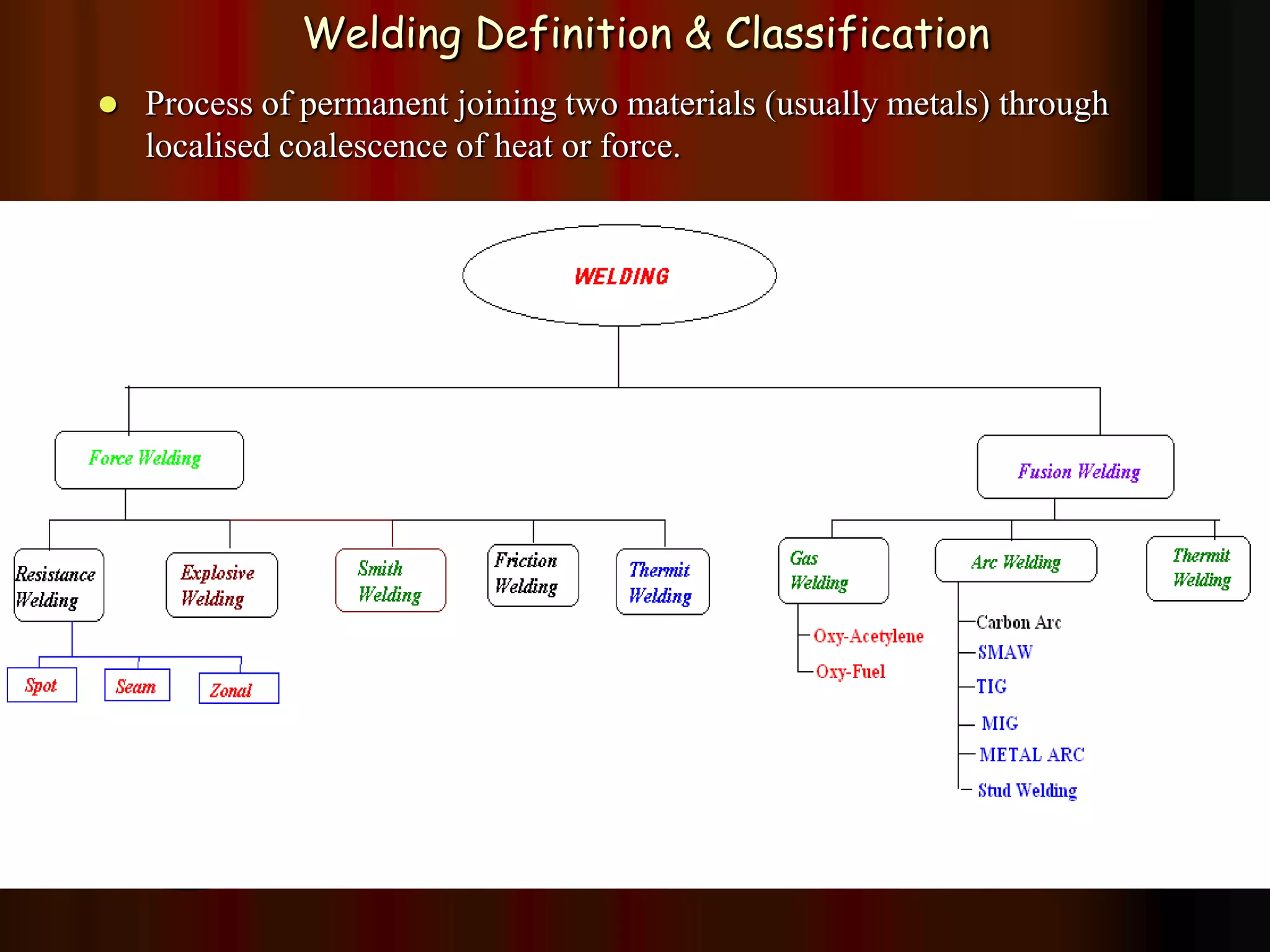
the slide shows the advance welding technic like as Tig And Mig Welding Process.
it help people to understand the advance manufacturing process for welding.
it made by Sk Samsuddin.
Welding is a fabrication process that lets you join materials like metals by using heat at high temperatures. Welding uses high temperature to join the materials, whereas soldering and brazing do not allow the base metal to melt. After cooling, the base metal and the filler metal get attached.
The welding process came to light when there was a search for the technique for developing iron into useful shapes. Welded blades were the first result of welding in the early years—the carburization of iron produced hard steel that was very brittle for usage. Later interlaying the rigid and soft iron with high-carbon material and hammer forging resulted in a tough and durable blade.
The process of welding uses filler material. The filler material is the pool of molten material that aids in the formation of a strong link between the base metal. The shielding process after welding the metals protects both the base and filler components from being oxidised.
From gas flame to ultrasound, many energies are used in welding like electron beams, electric arc, LASER, and friction. Now let us understand various types of welding.
Types of Welding
There are many types of welding used for various purposes under different situations. They are:
Manual welding includes:
Forge welding
Arc welding
Oxy-fuel welding
Shielded metal arc welding
Gas metal arc welding
submerged arc welding
flux-cored arc welding
electroslag welding
Laser beam welding
electron beam welding
magnetic pulse welding
friction stir welding
An introduction to various welding processes, suitable for all welding students and welding professionals like welder, supervisor, inspector, engineer.
Epistemic Interaction - tuning interfaces to provide information for AI supportAlan Dix
Paper presented at SYNERGY workshop at AVI 2024, Genoa, Italy. 3rd June 2024
https://alandix.com/academic/papers/synergy2024-epistemic/
As machine learning integrates deeper into human-computer interactions, the concept of epistemic interaction emerges, aiming to refine these interactions to enhance system adaptability. This approach encourages minor, intentional adjustments in user behaviour to enrich the data available for system learning. This paper introduces epistemic interaction within the context of human-system communication, illustrating how deliberate interaction design can improve system understanding and adaptation. Through concrete examples, we demonstrate the potential of epistemic interaction to significantly advance human-computer interaction by leveraging intuitive human communication strategies to inform system design and functionality, offering a novel pathway for enriching user-system engagements.
Accelerate your Kubernetes clusters with Varnish CachingThijs Feryn
A presentation about the usage and availability of Varnish on Kubernetes. This talk explores the capabilities of Varnish caching and shows how to use the Varnish Helm chart to deploy it to Kubernetes.
This presentation was delivered at K8SUG Singapore. See https://feryn.eu/presentations/accelerate-your-kubernetes-clusters-with-varnish-caching-k8sug-singapore-28-2024 for more details.
Essentials of Automations: Optimizing FME Workflows with ParametersSafe Software
Are you looking to streamline your workflows and boost your projects’ efficiency? Do you find yourself searching for ways to add flexibility and control over your FME workflows? If so, you’re in the right place.
Join us for an insightful dive into the world of FME parameters, a critical element in optimizing workflow efficiency. This webinar marks the beginning of our three-part “Essentials of Automation” series. This first webinar is designed to equip you with the knowledge and skills to utilize parameters effectively: enhancing the flexibility, maintainability, and user control of your FME projects.
Here’s what you’ll gain:
- Essentials of FME Parameters: Understand the pivotal role of parameters, including Reader/Writer, Transformer, User, and FME Flow categories. Discover how they are the key to unlocking automation and optimization within your workflows.
- Practical Applications in FME Form: Delve into key user parameter types including choice, connections, and file URLs. Allow users to control how a workflow runs, making your workflows more reusable. Learn to import values and deliver the best user experience for your workflows while enhancing accuracy.
- Optimization Strategies in FME Flow: Explore the creation and strategic deployment of parameters in FME Flow, including the use of deployment and geometry parameters, to maximize workflow efficiency.
- Pro Tips for Success: Gain insights on parameterizing connections and leveraging new features like Conditional Visibility for clarity and simplicity.
We’ll wrap up with a glimpse into future webinars, followed by a Q&A session to address your specific questions surrounding this topic.
Don’t miss this opportunity to elevate your FME expertise and drive your projects to new heights of efficiency.
State of ICS and IoT Cyber Threat Landscape Report 2024 previewPrayukth K V
The IoT and OT threat landscape report has been prepared by the Threat Research Team at Sectrio using data from Sectrio, cyber threat intelligence farming facilities spread across over 85 cities around the world. In addition, Sectrio also runs AI-based advanced threat and payload engagement facilities that serve as sinks to attract and engage sophisticated threat actors, and newer malware including new variants and latent threats that are at an earlier stage of development.
The latest edition of the OT/ICS and IoT security Threat Landscape Report 2024 also covers:
State of global ICS asset and network exposure
Sectoral targets and attacks as well as the cost of ransom
Global APT activity, AI usage, actor and tactic profiles, and implications
Rise in volumes of AI-powered cyberattacks
Major cyber events in 2024
Malware and malicious payload trends
Cyberattack types and targets
Vulnerability exploit attempts on CVEs
Attacks on counties – USA
Expansion of bot farms – how, where, and why
In-depth analysis of the cyber threat landscape across North America, South America, Europe, APAC, and the Middle East
Why are attacks on smart factories rising?
Cyber risk predictions
Axis of attacks – Europe
Systemic attacks in the Middle East
Download the full report from here:
https://sectrio.com/resources/ot-threat-landscape-reports/sectrio-releases-ot-ics-and-iot-security-threat-landscape-report-2024/
GraphRAG is All You need? LLM & Knowledge GraphGuy Korland
Guy Korland, CEO and Co-founder of FalkorDB, will review two articles on the integration of language models with knowledge graphs.
1. Unifying Large Language Models and Knowledge Graphs: A Roadmap.
https://arxiv.org/abs/2306.08302
2. Microsoft Research's GraphRAG paper and a review paper on various uses of knowledge graphs:
https://www.microsoft.com/en-us/research/blog/graphrag-unlocking-llm-discovery-on-narrative-private-data/
Slack (or Teams) Automation for Bonterra Impact Management (fka Social Soluti...Jeffrey Haguewood
Sidekick Solutions uses Bonterra Impact Management (fka Social Solutions Apricot) and automation solutions to integrate data for business workflows.
We believe integration and automation are essential to user experience and the promise of efficient work through technology. Automation is the critical ingredient to realizing that full vision. We develop integration products and services for Bonterra Case Management software to support the deployment of automations for a variety of use cases.
This video focuses on the notifications, alerts, and approval requests using Slack for Bonterra Impact Management. The solutions covered in this webinar can also be deployed for Microsoft Teams.
Interested in deploying notification automations for Bonterra Impact Management? Contact us at sales@sidekicksolutionsllc.com to discuss next steps.
Smart TV Buyer Insights Survey 2024 by 91mobiles.pdf91mobiles
91mobiles recently conducted a Smart TV Buyer Insights Survey in which we asked over 3,000 respondents about the TV they own, aspects they look at on a new TV, and their TV buying preferences.
UiPath Test Automation using UiPath Test Suite series, part 3DianaGray10
Welcome to UiPath Test Automation using UiPath Test Suite series part 3. In this session, we will cover desktop automation along with UI automation.
Topics covered:
UI automation Introduction,
UI automation Sample
Desktop automation flow
Pradeep Chinnala, Senior Consultant Automation Developer @WonderBotz and UiPath MVP
Deepak Rai, Automation Practice Lead, Boundaryless Group and UiPath MVP
Kubernetes & AI - Beauty and the Beast !?! @KCD Istanbul 2024Tobias Schneck
As AI technology is pushing into IT I was wondering myself, as an “infrastructure container kubernetes guy”, how get this fancy AI technology get managed from an infrastructure operational view? Is it possible to apply our lovely cloud native principals as well? What benefit’s both technologies could bring to each other?
Let me take this questions and provide you a short journey through existing deployment models and use cases for AI software. On practical examples, we discuss what cloud/on-premise strategy we may need for applying it to our own infrastructure to get it to work from an enterprise perspective. I want to give an overview about infrastructure requirements and technologies, what could be beneficial or limiting your AI use cases in an enterprise environment. An interactive Demo will give you some insides, what approaches I got already working for real.
Encryption in Microsoft 365 - ExpertsLive Netherlands 2024Albert Hoitingh
In this session I delve into the encryption technology used in Microsoft 365 and Microsoft Purview. Including the concepts of Customer Key and Double Key Encryption.
Key Trends Shaping the Future of Infrastructure.pdfCheryl Hung
Keynote at DIGIT West Expo, Glasgow on 29 May 2024.
Cheryl Hung, ochery.com
Sr Director, Infrastructure Ecosystem, Arm.
The key trends across hardware, cloud and open-source; exploring how these areas are likely to mature and develop over the short and long-term, and then considering how organisations can position themselves to adapt and thrive.
2. Welding Definition & Classification
Process of permanent joining two materials (usually metals) through
localised coalescence of heat or force.
3. Selection of the welding process
Nature of joint
Materials to be welded
Geometry of component
Quality
Strength & mechanical properties
Time factor
Cost
Welding Environment
Source of energy
7. Comparison b/w Flames
S. No. Neutral Flame Oxidizing flame Reducing Flame
Temperature
Materials
O2:C2H2
3200
CI, MS, SS Cu,
Al
1:1
3300
Cu or Zinc alloys
1.2:1
3100
Lead ,HSS
1:1.2
8. Oxy- Fuel Welding
Oxygen is used with other fuel gas to
produce flame & coalescence of heat.
1. Hydrogen
2. Propane
3. Butane
4. Natural gas
9. Advantage
Most versatile.
Considerable control over temp. by varying supply of gases.
Deposition rate is controlled
Low cost & versatile equipment
Portable & low maintenance
10. Disadvantage
Not for heavy sections
Lower temp of flame limits its use.
Flux used causes irritating smoke.
Refractory metals & reactive metals cannot be welded
Long heat up time
Larger HAZ
More safety & handling problem with gases.
11. APPLICATION
Joining up to thickness 8 mm.
Materials having harmful effect of rapid heating &
cooling.
Materials like- CI, SS, LCS, HCS, Cu, Zn, Ni, Mg etc.
In automobile & aircraft industry for sheet-metal
applications.
13. PRINCIPLE
Heat is generated from arc struck between
an electrode & work piece.
Temp.= 5500 Celsius
Stand off dis.= 1 - 5 mm.
Arc length = 0.6 - 0.8 of electrode dia.
Current =150 – 1000 Amp.
Voltage = 40 - 45 volts (DC)
50 -60 volts (AC)
16. Tungsten Inert Gas ARC WELDING
(TIG/GTAW)
• Heat is generated by electric arc struck
between a tungsten electrode and the job.
• A shielding gas (argon helium, nitrogen, etc.)
is used to avoid atmospheric contamination of
the molten weld pool.
• A filler metal may be added, if required.
17.
18.
19. SPECIFICATION 0f TIG
• Temp. = 5500 Celsius
• Welding torch angle= 70- 80 degrees
• Filler rod angle= 10-20 degree
• Current= 100-500 Amp
• Electrode diameter = 2-5 mm
• Filler rod diameter = 2-6 mm
• Flow rate of gases = 7-11 lit/minutes
• Electrode material = W, W alloys, Thoriated W,
Zerconiated W.
• Shielding gases = Ar, Ne, He etc
20. ADVANTAGE
Applicable to wide range of materials
(ferrous & non-ferrous).
Good for welding thin sections (0.125mm)
and delicate work pieces
high quality and appearance of weld.
Clear visibility
No flux entrapment risk
21. DISADVANTAGE
Restricted to flat or horizontal welding.
W in weld pool causes seviour problem
Filler rod end causes contamination of
weldment
Costly.
22. APPLICATION
Al, Mg, Cu, Ni, and their alloys.
Carbon alloys, SS, High temp & hardsurfacingalloys like Zr, Ti.
Welding thinner sections.
Welding of expansion bellows, transistor cases, instrument
diaphragm& sealingjoints
Rocker motor chamber fabrication in launch vehicles.
23. METAL INHERT GAS ARC
WELDING
(MIG)
• Heat is generated by electric arc struck between a
consumable metal electrode and the job.
• A shielding gas (argon helium, nitrogen, etc.) is
used to avoid atmospheric contamination of the
molten weld pool.
• It needs Wire Electrode feed mechanism.
25. ADVANTAGE
Versatility - readily applied to a variety of applications and a
wide choice of electrodes
Relative simplicity and portability of equipment
Low cost
Adaptable to confined spaces and remote locations
Suitable for out-of-position welding
26. DISADVANTAGE
Not as productive as continuous wire processes
Likely to be more costly to deposit a given quantity of metal
Frequent stop/starts to change electrode
Relatively high metal wastage (electrode stubs)
Current limits are lower than for continuous or automatic processes
(reduces deposition rate)
27. RESISTANCE WELDING
• Heat generated at interface due to resistance offered.
H= I*I*R*T
• Autogenous Weld (no filler needed)
31. Welding steps
SQUEEZE TIME- Both workpices are squeezed together, by
app of pressure by electrodes.
CURRENT SUPPPLY- Now welding current is applied for short
time.
HOLD TIME- Current is off but the forces remains applied for
proper weld.
OFF TIME- the forces on the work is removed.
33. ADVANTAGE
Low cost
High welding speed
Less skilled labor.
Elimination of wrapping/distortion of parts
High uniformity & quality of products
Easy automation
No need of edge preparation
34. APPLICATION
Spot weld up to 12.5mm thickness
Attachment of braces, brackets, pods, clips of box,
container & trays are welded
Automobile & aircraft industry.
Joining sheet metals
36. ADVANTAGE
Gas & liquid tight welds.
Overlap may be less than spot
welding
Single seam weld or parallel
welds can be produced
DISADVANTAGE
ONLY STRAIGHT OR UNIFORM
CURVE CAN BE WELDED
DIFFICULT TO WELD THICKNESS
MORE THAN 3MM
SPECIAL DESIGNE OF WELD
ROLLS
APPLICATION
•ROUND, SQUARE, RECTANGULAR WELDS
•EXPECT Cu & HIGH Cu ALLOYS ALL OTHER MATERIALS ARE
WELDED
•CAN BE USED FOR LAP, BUTT JOINTS
38. PRINCIPLE
Current flow is concentrated at the contact surface by
an embossed projection.
Projection effectively localizes the current
39. ADVANTAGE
No of simultaneous weld
Thick joints
Less interference by rust, oil & work coating
Long electrode life
Can be used for complicated shapes
Better heat balance
Lower current & pressure
40. DISADVANTAGE
Limited to metals which can be embossed
For proper weld all projection must have equal height.
41. APPLICATON
Various automobile parts
Small fasteners & nuts can be welded
Refrigerator condenser
Cross wire welding
Grating of boilers
Household grills.
42. FRICTION WELDING
• solid-state welding
• Heat through mechanical friction b/w a moving work
piece & a stationary component .
• Technically, because no melt occurs, so its a forging
technique .
45. Process Specification
Peripheral velocity= 50-200 m/min
Axial pressure= 30-200 N/mm2
Material Welded- Al, Ti, Ni, Cu and their alloys,
Brass, Bronze, Mg, Carbon steel, SS, Tantalum etc..
Dissimilar material welds- Alloy steel to carbon
steel, super alloys to carbon steel, SS to carbon steel
46. ELECTROSLAG WELDING
• Highly productive, single pass process (thickness 25-300 mm)
in a vertical position
• Arc is initially struck by wire fed into the weld location & then
flux is added.
• Additional flux is added until the molten slag extinguishes
the arc.
• The wire is then continually fed and the filler metal are then
melted using the electrical resistance of the molten slag to
cause coalescence.
49. Points to Consider
ADVANTAGE
Butt & T joint square face
Large thickness upto 600mm
Alloy steel are welded
Extremely high deposition rates
Residual stress & distortion is low
Low flux consumption
No spattering & flashing occurs.
DISADVANTAGE
More costly for section below
60mm
Hot cracking
Tends to produce larger grain size
Limited to vertical & uphill
position
Tendency to notch sensitivity in
HAZ
50. APPLICATION
Heavy casting, forging plates (butt weld)
Welding of thick LCS & MCS.
High strength structure steel
Large cross-section of flyovers, structures, marine ships etc.
51. WELDING of CAST IRON
Good fluidity & high solidification shrinkage.
SMAW, GMAW, Oxy-fuel, flux coated arc, Termite welding processes are applicable
Grey CI:
Certain precaution like preheating & low cooling rates.
White CI:
Considered as un weldable.
Malleable CI:
Post weld heat treatment
Very low cooling rates to prevent it to change to White CI.
Nodular CI:
Proper flux is needed to prevent losing of Mg which is responsible for ductility.
52. WELDING of ALUMINIUM
Higher heat input needed (Reverse DC polarity)
Thick sections needs preheating
High reflective hence no red colour is appered during heating
GMAW, GTAW, Resistance welding is common.
PAW, EBM are specially used
SMAW & oxy fuel welding are used when strength is not essential
53. WELDING of STEEL
LCS(0.13-0.3 %C):
arcweldingispreferred
MCS(0.3-0.5 %C):
Preweldheattreatmentiscommon
Post weldheattreatmentissometimesnecessaryforthinsections
HCS(0.5-1.5%C):
Pre& Postweldeattreatmentis essential
LowH, S weldingprocess
Shouldbe weldedinannealedcondition
HIGH STRENGTH LOW ALLOY STEELS:
SMAW, TIG/MIG,Fluxcoated,Submergedarcweldingareapplicable.
LowHydrogenwelding
Resistanceweldingcanbe applied
54. SOLDERING
• Two or more metal items are joined together by melting and
flowing a filler metal into the joint
• The filler metal having a relatively low melting point
• Soldering is characterized by the melting point of the filler
metal, is below 400 °C
• The filler metal used in the process is called SOLDER
• It is distinguished from welding by the base metals not being
melted during the joining
56. Application
Assembling electronic components to printed circuit
boards
Permanent but reversible connections between copper
pipes in Plumbing systems
Jewelry components are assembled and repaired by
soldering
57. Solders
tin-lead(general purpose)
tin-zincfor joining aluminum
lead-silver for strengthat higher thanroomtemperature
cadmium-silver for strengthat high temperatures
zinc-aluminumfor aluminumand corrosionresistance
tin-silver and tin-bismuthfor electronics