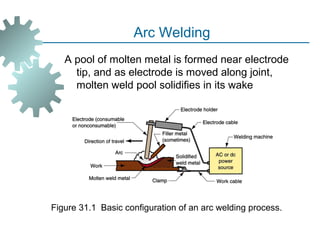
SlideShare a Scribd company logo
WELDING PROCESSES
1. Arc Welding
2. Resistance Welding
3. Oxyfuel Gas Welding
4. Other Fusion Welding Processes
5. Solid State Welding
6. Weld Quality
7. Weldability
Two Categories of Welding Processes
 Fusion welding - coalescence is accomplished
by melting the two parts to be joined, in some
cases adding filler metal to the joint
 Examples: arc welding, resistance spot
welding, oxyfuel gas welding
 Solid state welding - heat and/or pressure are
used to achieve coalescence, but no melting of
base metals occurs and no filler metal is added
 Examples: forge welding, diffusion welding,
friction welding
Arc Welding (AW)
A fusion welding process in which coalescence of
the metals is achieved by the heat from an
electric arc between an electrode and the work
 Electric energy from the arc produces
temperatures ~ 10,000 F (5500 C), hot enough
to melt any metal
 Most AW processes add filler metal to increase
volume and strength of weld joint
What is an Electric Arc?
An electric arc is a discharge of electric current
across a gap in a circuit
 It is sustained by an ionized column of gas
(plasma) through which the current flows
 To initiate the arc in AW, electrode is brought
into contact with work and then quickly
separated from it by a short distance
A pool of molten metal is formed near electrode
tip, and as electrode is moved along joint,
molten weld pool solidifies in its wake
Figure 31.1 Basic configuration of an arc welding process.
Arc Welding
Two Basic Types of AW Electrodes
 Consumable – consumed during welding
process
 Source of filler metal in arc welding
 Nonconsumable – not consumed during
welding process
 Filler metal must be added separately
Consumable Electrodes
 Forms of consumable electrodes
 Welding rods (a.k.a. sticks) are 9 to 18
inches and 3/8 inch or less in diameter and
must be changed frequently
 Weld wire can be continuously fed from
spools with long lengths of wire, avoiding
frequent interruptions
 In both rod and wire forms, electrode is
consumed by arc and added to weld joint as
filler metal
Nonconsumable Electrodes
 Made of tungsten which resists melting
 Gradually depleted during welding
(vaporization is principal mechanism)
 Any filler metal must be supplied by a separate
wire fed into weld pool
Arc Shielding
 At high temperatures in AW, metals are
chemically reactive to oxygen, nitrogen, and
hydrogen in air
 Mechanical properties of joint can be
seriously degraded by these reactions
 To protect operation, arc must be shielded
from surrounding air in AW processes
 Arc shielding is accomplished by:
 Shielding gases, e.g., argon, helium, CO2
 Flux
Flux
A substance that prevents formation of oxides
and other contaminants in welding, or dissolves
them and facilitates removal
 Provides protective atmosphere for welding
 Stabilizes arc
 Reduces spatter
Various Flux Application Methods
 Pouring granular flux onto welding operation
 Stick electrode coated with flux material that
melts during welding to cover operation
 Tubular electrodes in which flux is contained in
the core and released as electrode is
consumed
Power Source in Arc Welding
 Direct current (DC) vs. Alternating current (AC)
 AC machines less expensive to purchase
and operate, but generally restricted to
ferrous metals
 DC equipment can be used on all metals
and is generally noted for better arc control
Consumable Electrode AW Processes
 Shielded Metal Arc Welding
 Gas Metal Arc Welding
 Flux Cored Arc Welding‑
 Electrogas Welding
 Submerged Arc Welding
Shielded Metal Arc Welding (SMAW)
Uses a consumable electrode consisting of a filler
metal rod coated with chemicals that provide
flux and shielding
 Sometimes called "stick welding"
 Power supply, connecting cables, and
electrode holder available for a few thousand
dollars
Figure 31.3 Shielded metal arc welding (SMAW).
Shielded Metal Arc Welding
Figure 31.2 Shielded
metal arc welding (stick
welding) performed by a
(human) welder (photo
courtesy of Hobart
Brothers Co.).
Shielded Metal Arc Welding
SMAW Applications
 Used for steels, stainless steels, cast
irons, and certain nonferrous alloys
 Not used or rarely used for aluminum
and its alloys, copper alloys, and
titanium
Gas Metal Arc Welding (GMAW)
Uses a consumable bare metal wire as
electrode and shielding accomplished by
flooding arc with a gas
 Wire is fed continuously and automatically
from a spool through the welding gun
 Shielding gases include inert gases such as
argon and helium for aluminum welding, and
active gases such as CO2 for steel welding
 Bare electrode wire plus shielding gases
eliminate slag on weld bead - no need for
manual grinding and cleaning of slag
Figure 31.4 Gas metal arc welding (GMAW).
Gas Metal Arc Welding
GMAW Advantages over SMAW
 Better arc time because of continuous wire
electrode
 Sticks must be periodically changed in
SMAW
 Better use of electrode filler metal than SMAW
 End of stick cannot be used in SMAW
 Higher deposition rates
 Eliminates problem of slag removal
 Can be readily automated
Flux Cored Arc Welding (FCAW)‑
Adaptation of shielded metal arc welding, to
overcome limitations of stick electrodes
 Electrode is a continuous consumable tubing
(in coils) containing flux and other ingredients
(e.g., alloying elements) in its core
 Two versions:
 Self shielded FCAW - core includes‑
compounds that produce shielding gases
 Gas shielded FCAW - uses externally‑
applied shielding gases
Figure 31.6 Flux cored arc welding. Presence or absence of externally‑
supplied shielding gas distinguishes the two types: (1) self shielded,‑
in which core provides ingredients for shielding, and (2) gas shielded,‑
which uses external shielding gases.
Flux-Cored Arc Welding
Electrogas Welding (EGW)
Uses a continuous consumable electrode, either
flux cored wire or bare wire with externally‑
supplied shielding gases, and molding shoes to
contain molten metal
 When flux cored electrode wire is used and no‑
external gases are supplied, then special case
of self shielded FCAW‑
 When a bare electrode wire used with shielding
gases from external source, then special case
of GMAW
Figure 31.7 Electrogas welding using flux cored electrode wire:‑
(a) front view with molding shoe removed for clarity, and (b)
side view showing molding shoes on both sides.
Electrogas Welding
Submerged Arc Welding (SAW)
Uses a continuous, consumable bare wire
electrode, with arc shielding provided by a
cover of granular flux
 Electrode wire is fed automatically from a
coil
 Flux introduced into joint slightly ahead of arc
by gravity from a hopper
 Completely submerges operation,
preventing sparks, spatter, and radiation
Figure 31.8 Submerged arc welding.
Submerged Arc Welding
SAW Applications and Products
 Steel fabrication of structural shapes (e.g.,
I beams)‑
 Seams for large diameter pipes, tanks, and
pressure vessels
 Welded components for heavy machinery
 Most steels (except hi C steel)
 Not good for nonferrous metals
Non-consumable Electrode Processes
 Gas Tungsten Arc Welding
 Plasma Arc Welding
 Carbon Arc Welding
 Stud Welding
Gas Tungsten Arc Welding (GTAW)
Uses a non-consumable tungsten electrode
and an inert gas for arc shielding
 Melting point of tungsten = 3410°C (6170°F)
 A.k.a. Tungsten Inert Gas (TIG) welding
 In Europe, called "WIG welding"
 Used with or without a filler metal
 When filler metal used, it is added to
weld pool from separate rod or wire
 Applications: aluminum and stainless steel
most common
Figure 31.9 Gas tungsten arc welding.
Gas Tungsten Arc Welding
Advantages / Disadvantages of GTAW
Advantages:
 High quality welds for suitable applications
 No spatter because no filler metal through
arc
 Little or no post-weld cleaning because no
flux
Disadvantages:
 Generally slower and more costly than
consumable electrode AW processes
Plasma Arc Welding (PAW)
Special form of GTAW in which a constricted
plasma arc is directed at weld area
 Tungsten electrode is contained in a nozzle
that focuses a high velocity stream of inert gas
(argon) into arc region to form a high velocity,
intensely hot plasma arc stream
 Temperatures in PAW reach 28,000°C
(50,000°F), due to constriction of arc,
producing a plasma jet of small diameter and
very high energy density
Figure 31.10 Plasma arc welding (PAW).
Plasma Arc Welding
Advantages / Disadvantages of PAW
Advantages:
 Good arc stability
 Better penetration control than other AW
 High travel speeds
 Excellent weld quality
 Can be used to weld almost any metals
Disadvantages:
 High equipment cost
 Larger torch size than other AW
 Tends to restrict access in some joints
Resistance Welding (RW)
A group of fusion welding processes that use a
combination of heat and pressure to
accomplish coalescence
 Heat generated by electrical resistance to
current flow at junction to be welded
 Principal RW process is resistance spot
welding (RSW)
Figure 31.12 Resistance
welding, showing the
components in spot
welding, the main
process in the RW
group.
Resistance Welding
Components in Resistance Spot Welding
 Parts to be welded (usually sheet metal)
 Two opposing electrodes
 Means of applying pressure to squeeze parts
between electrodes
 Power supply from which a controlled current
can be applied for a specified time duration
Advantages / Drawbacks of RW
Advantages:
 No filler metal required
 High production rates possible
 Lends itself to mechanization and automation
 Lower operator skill level than for arc welding
 Good repeatability and reliability
Disadvantages:
 High initial equipment cost
 Limited to lap joints for most RW processes
Resistance Spot Welding (RSW)
Resistance welding process in which fusion of
faying surfaces of a lap joint is achieved at one
location by opposing electrodes
 Used to join sheet metal parts using a series of
spot welds
 Widely used in mass production of
automobiles, appliances, metal furniture, and
other products made of sheet metal
 Typical car body has ~ 10,000 spot welds
 Annual production of automobiles in the
world is measured in tens of millions of units
Figure 31.13 (a) Spot welding cycle, (b) plot of squeezing force & current
in cycle (1) parts inserted between electrodes, (2) electrodes close,
force applied, (3) current on, (4) current off, (5) electrodes opened.
Spot Welding Cycle
Resistance Seam Welding (RSEW)
Uses rotating wheel electrodes to produce a
series of overlapping spot welds along lap
joint
 Can produce air tight joints‑
 Applications:
 Gasoline tanks
 Automobile mufflers
 Various other sheet metal containers
Figure 31.15 Resistance seam welding (RSEW).
Resistance Seam Welding
Resistance Projection Welding (RPW)
A resistance welding process in which
coalescence occurs at one or more small
contact points on parts
 Contact points determined by design of parts to
be joined
 May consist of projections, embossments,
or localized intersections of parts
Figure 31.17 Resistance projection welding (RPW): (1) start of operation,
contact between parts is at projections; (2) when current is applied,
weld nuggets similar to spot welding are formed at the projections.
Resistance Projection Welding
Oxyfuel Gas Welding (OFW)
Group of fusion welding operations that burn
various fuels mixed with oxygen
 OFW employs several types of gases, which is
the primary distinction among the members of
this group
 Oxyfuel gas is also used in flame cutting
torches to cut and separate metal plates and
other parts
 Most important OFW process is oxyacetylene
welding
Oxyacetylene Welding (OAW)
Fusion welding performed by a high temperature
flame from combustion of acetylene and
oxygen
 Flame is directed by a welding torch
 Filler metal is sometimes added
 Composition must be similar to base metal
 Filler rod often coated with flux to clean
surfaces and prevent oxidation
Figure 31.21 A typical oxyacetylene welding operation (OAW).
Oxyacetylene Welding
Acetylene (C2H2)
 Most popular fuel among OFW group because
it is capable of higher temperatures than any
other up to 3480‑ °C (6300°F)
 Two stage chemical reaction of acetylene and
oxygen:
 First stage reaction (inner cone of flame):
C2H2 + O2 → 2CO + H2 + heat
 Second stage reaction (outer envelope):
2CO + H2 + 1.5O2 → 2CO2 + H2O + heat
 Maximum temperature reached at tip of inner
cone, while outer envelope spreads out and
shields work surfaces from atmosphere
Figure 31.22 The neutral flame from an oxyacetylene torch
indicating temperatures achieved.
Oxyacetylene Torch
Alternative Gases for OFW
 Methylacetylene Propadiene (MAPP)‑
 Hydrogen
 Propylene
 Propane
 Natural Gas
Other Fusion Welding Processes
FW processes that cannot be classified as arc,
resistance, or oxyfuel welding
 Use unique technologies to develop heat for
melting
 Applications are typically unique
 Processes include:
 Electron beam welding
 Laser beam welding
 Electroslag welding
 Thermit welding
Electron Beam Welding (EBW)
Fusion welding process in which heat for welding
is provided by a highly focused, high intensity‑ ‑
stream of electrons striking work surface
 Electron beam gun operates at:
 High voltage (e.g., 10 to 150 kV typical) to
accelerate electrons
 Beam currents are low (measured in
milliamps)
 Power in EBW not exceptional, but power
density is
EBW Advantages / Disadvantages
Advantages:
 High quality welds, deep and narrow profiles‑
 Limited heat affected zone, low thermal
distortion
 High welding speeds
 No flux or shielding gases needed
Disadvantages:
 High equipment cost
 Precise joint preparation & alignment required
 Vacuum chamber required
 Safety concern: EBW generates x rays‑
Laser Beam Welding (LBW)
Fusion welding process in which coalescence is
achieved by energy of a highly concentrated,
coherent light beam focused on joint
 Laser = "light amplification by stimulated
emission of radiation"
 LBW normally performed with shielding gases
to prevent oxidation
 Filler metal not usually added
 High power density in small area, so LBW often
used for small parts
Comparison: LBW vs. EBW
 No vacuum chamber required for LBW
 No x rays emitted in LBW‑
 Laser beams can be focused and directed by
optical lenses and mirrors
 LBW not capable of the deep welds and high
depth to width ratios of EBW‑ ‑
 Maximum LBW depth = ~ 19 mm (3/4 in),
whereas EBW depths = 50 mm (2 in)
Thermit Welding (TW)
FW process in which heat for coalescence is
produced by superheated molten metal from
the chemical reaction of thermite
 Thermite = mixture of Al and Fe3O4 fine
powders that produce an exothermic reaction
when ignited
 Also used for incendiary bombs
 Filler metal obtained from liquid metal
 Process used for joining, but has more in
common with casting than welding
Figure 31.25 Thermit welding: (1) Thermit ignited; (2) crucible
tapped, superheated metal flows into mold; (3) metal solidifies to
produce weld joint.
Thermit Welding
TW Applications
 Joining of railroad rails
 Repair of cracks in large steel castings and
forgings
 Weld surface is often smooth enough that no
finishing is required
Solid State Welding (SSW)
 Coalescence of part surfaces is achieved by:
 Pressure alone, or
 Heat and pressure
 If both heat and pressure are used, heat
is not enough to melt work surfaces
 For some SSW processes, time is also a
factor
 No filler metal is added
 Each SSW process has its own way of creating
a bond at the faying surfaces
Success Factors in SSW
 Essential factors for a successful solid state
weld are that the two faying surfaces must be:
 Very clean
 In very close physical contact with each
other to permit atomic bonding
SSW Advantages over FW Processes
 If no melting, then no heat affected zone, so
metal around joint retains original properties
 Many SSW processes produce welded joints
that bond the entire contact interface between
two parts rather than at distinct spots or seams
 Some SSW processes can be used to bond
dissimilar metals, without concerns about
relative melting points, thermal expansions,
and other problems that arise in FW
Solid State Welding Processes
 Forge welding
 Cold welding
 Roll welding
 Hot pressure welding
 Diffusion welding
 Explosion welding
 Friction welding
 Ultrasonic welding
Forge Welding
Welding process in which components to be
joined are heated to hot working temperature
range and then forged together by hammering
or similar means
 Historic significance in development of
manufacturing technology
 Process dates from about 1000 B.C., when
blacksmiths learned to weld two pieces of
metal
 Of minor commercial importance today except
for its variants
Roll Welding (ROW)
SSW process in which pressure sufficient to
cause coalescence is applied by means of
rolls, either with or without external heat
 Variation of either forge welding or cold
welding, depending on whether heating of
workparts is done prior to process
 If no external heat, called cold roll welding
 If heat is supplied, hot roll welding
Figure 31.26 Roll welding (ROW).
Roll Welding
Roll Welding Applications
 Cladding stainless steel to mild or low alloy
steel for corrosion resistance
 Bimetallic strips for measuring temperature
 "Sandwich" coins for U.S mint
Diffusion Welding (DFW)
SSW process uses heat and pressure, usually in
a controlled atmosphere, with sufficient time for
diffusion and coalescence to occur
 Temperatures ≤ 0.5 Tm
 Plastic deformation at surfaces is minimal
 Primary coalescence mechanism is solid state
diffusion
 Limitation: time required for diffusion can range
from seconds to hours
DFW Applications
 Joining of high strength and refractory metals‑
in aerospace and nuclear industries
 Can be used to join either similar and dissimilar
metals
 For joining dissimilar metals, a filler layer of
different metal is often sandwiched between
base metals to promote diffusion
Explosion Welding (EXW)
SSW process in which rapid coalescence of two
metallic surfaces is caused by the energy of a
detonated explosive
 No filler metal used
 No external heat applied
 No diffusion occurs - time is too short
 Bonding is metallurgical, combined with
mechanical interlocking that results from a
rippled or wavy interface between the metals
Commonly used to bond two dissimilar metals,
in particular to clad one metal on top of a
base metal over large areas
Figure 31.27 Explosive welding (EXW): (1) setup in the
parallel configuration, and (2) during detonation of the
explosive charge.
Explosive Welding
Friction Welding (FRW)
SSW process in which coalescence is achieved
by frictional heat combined with pressure
 When properly carried out, no melting occurs at
faying surfaces
 No filler metal, flux, or shielding gases normally
used
 Process yields a narrow HAZ
 Can be used to join dissimilar metals
 Widely used commercial process, amenable to
automation and mass production
Figure 31.28 Friction welding (FRW): (1) rotating part, no contact; (2)
parts brought into contact to generate friction heat; (3) rotation
stopped and axial pressure applied; and (4) weld created.
Friction Welding
Applications / Limitations of FRW
Applications:
 Shafts and tubular parts
 Industries: automotive, aircraft, farm
equipment, petroleum and natural gas
Limitations:
 At least one of the parts must be rotational
 Flash must usually be removed
 Upsetting reduces the part lengths (which must
be taken into consideration in product design)
Ultrasonic Welding (USW)
Two components are held together, oscillatory
shear stresses of ultrasonic frequency are
applied to interface to cause coalescence
 Oscillatory motion breaks down any surface
films to allow intimate contact and strong
metallurgical bonding between surfaces
 Although heating of surfaces occurs,
temperatures are well below Tm
 No filler metals, fluxes, or shielding gases
 Generally limited to lap joints on soft materials
such as aluminum and copper
Figure 31.29 Ultrasonic welding (USW): (a) general setup for
a lap joint; and (b) close up of weld area.‑
Ultrasonic Welding
USW Applications
 Wire terminations and splicing in electrical
and electronics industry
 Eliminates need for soldering
 Assembly of aluminum sheet metal panels
 Welding of tubes to sheets in solar panels
 Assembly of small parts in automotive
industry
Weldability
Capacity of a metal or combination of metals to
be welded into a suitably designed structure,
and for the resulting weld joint(s) to possess
the required metallurgical properties to perform
satisfactorily in intended service
 Good weldability characterized by:
 Ease with which welding process is
accomplished
 Absence of weld defects
 Acceptable strength, ductility, and
toughness in welded joint

More Related Content

What's hot

Welding Basics
Welding BasicsWelding Basics
Welding Basics
mrsovek
 
Welding Presentation
Welding Presentation Welding Presentation
Welding Presentation
arun kumar
 
Solid state welding
Solid state weldingSolid state welding
Solid state welding
Raju Panchal
 
Welding and its types
Welding and its types Welding and its types
Welding and its types
NUST Stuff
 
Forging
ForgingForging
SHEET METAL PROCESSES
SHEET METAL PROCESSESSHEET METAL PROCESSES
SHEET METAL PROCESSES
laxtwinsme
 
Resistance welding
Resistance weldingResistance welding
Resistance welding
Jalu Sugiantoro
 
Heat Treatment Process
Heat Treatment ProcessHeat Treatment Process
Heat Treatment Process
Mohammud Hanif Dewan M.Phil.
 
Solid state welding
Solid state weldingSolid state welding
Solid state welding
Abdullah Mansoor
 
Joining processes (welding)
Joining processes (welding)Joining processes (welding)
Joining processes (welding)
9665930613
 
Metal Joining Processes
Metal Joining ProcessesMetal Joining Processes
Metal Joining Processes
Vishal Shinde
 
Submerged arc welding
Submerged arc weldingSubmerged arc welding
Submerged arc welding
faheem maqsood
 
CASTING PPT
CASTING PPTCASTING PPT
CASTING PPT
saurabh015
 
Tig welding
Tig welding Tig welding
Tig welding
Lahiru Dilshan
 
PPT of Plasma arc welding , detailed overview (PAW)
PPT of Plasma arc welding , detailed overview (PAW)PPT of Plasma arc welding , detailed overview (PAW)
Casting process
Casting processCasting process
Casting process
Kiran Wakchaure
 
ppt on Sheet metal process
ppt on Sheet metal processppt on Sheet metal process
ppt on Sheet metal process
sumant99
 
Weldability
WeldabilityWeldability
Weldability
Mubassir Ghoniya
 
METAL CASTING PROCESSES
METAL CASTING PROCESSESMETAL CASTING PROCESSES
METAL CASTING PROCESSES
Balamurugan Subburaj
 
arc welding
arc weldingarc welding

What's hot (20)

Welding Basics
Welding BasicsWelding Basics
Welding Basics
 
Welding Presentation
Welding Presentation Welding Presentation
Welding Presentation
 
Solid state welding
Solid state weldingSolid state welding
Solid state welding
 
Welding and its types
Welding and its types Welding and its types
Welding and its types
 
Forging
ForgingForging
Forging
 
SHEET METAL PROCESSES
SHEET METAL PROCESSESSHEET METAL PROCESSES
SHEET METAL PROCESSES
 
Resistance welding
Resistance weldingResistance welding
Resistance welding
 
Heat Treatment Process
Heat Treatment ProcessHeat Treatment Process
Heat Treatment Process
 
Solid state welding
Solid state weldingSolid state welding
Solid state welding
 
Joining processes (welding)
Joining processes (welding)Joining processes (welding)
Joining processes (welding)
 
Metal Joining Processes
Metal Joining ProcessesMetal Joining Processes
Metal Joining Processes
 
Submerged arc welding
Submerged arc weldingSubmerged arc welding
Submerged arc welding
 
CASTING PPT
CASTING PPTCASTING PPT
CASTING PPT
 
Tig welding
Tig welding Tig welding
Tig welding
 
PPT of Plasma arc welding , detailed overview (PAW)
PPT of Plasma arc welding , detailed overview (PAW)PPT of Plasma arc welding , detailed overview (PAW)
PPT of Plasma arc welding , detailed overview (PAW)
 
Casting process
Casting processCasting process
Casting process
 
ppt on Sheet metal process
ppt on Sheet metal processppt on Sheet metal process
ppt on Sheet metal process
 
Weldability
WeldabilityWeldability
Weldability
 
METAL CASTING PROCESSES
METAL CASTING PROCESSESMETAL CASTING PROCESSES
METAL CASTING PROCESSES
 
arc welding
arc weldingarc welding
arc welding
 

Similar to Metal Joining Process

Welding process -SPU.ppt
Welding process -SPU.pptWelding process -SPU.ppt
Welding process -SPU.ppt
SheetalUdgave1
 
Welding and types
Welding and typesWelding and types
Welding and types
KANNANS94
 
Welding process /certified fixed orthodontic courses by Indian dental acad...
Welding process    /certified fixed orthodontic courses by Indian dental acad...Welding process    /certified fixed orthodontic courses by Indian dental acad...
Welding process /certified fixed orthodontic courses by Indian dental acad...
Indian dental academy
 
Arc Welding
Arc WeldingArc Welding
Arc Welding
hafizarsalan3
 
Welding Assignment
Welding AssignmentWelding Assignment
Welding Assignment
Dil Shah
 
Types%20of%20 Welding[1]
Types%20of%20 Welding[1]Types%20of%20 Welding[1]
Types%20of%20 Welding[1]guestbd7851
 
a159280334379.pdf
a159280334379.pdfa159280334379.pdf
a159280334379.pdf
Waseelsultan
 
Introduction to welding processes
Introduction to welding processesIntroduction to welding processes
Introduction to welding processes
Sankaran Srinivasan
 
Welding process
Welding processWelding process
Welding process
ArunMK17
 
Welding & joining
Welding & joiningWelding & joining
Welding & joining
Arup Nath
 
welding-160706051720.pptx
welding-160706051720.pptxwelding-160706051720.pptx
welding-160706051720.pptx
039JagadeeswaranS
 
Flux cored arc welding
Flux cored arc weldingFlux cored arc welding
Flux cored arc welding
faheem maqsood
 
Welding Processes
Welding ProcessesWelding Processes
Welding Processes
M Siva Kumar
 
Advanced Welding Technology
Advanced Welding TechnologyAdvanced Welding Technology
Advanced Welding Technology
abhibhavesh
 
Arc welding, smaw, saw, mig, tig advantage
Arc welding, smaw, saw, mig, tig advantageArc welding, smaw, saw, mig, tig advantage
Arc welding, smaw, saw, mig, tig advantage
mahendra singh
 
Advance Welding Process
Advance Welding ProcessAdvance Welding Process
Advance Welding Process
Sk Samsuddin
 
Types of welding
Types of weldingTypes of welding
Types of welding
Bilalwahla
 
Welding (WorkShop) Assig # 1
Welding (WorkShop) Assig # 1Welding (WorkShop) Assig # 1
Welding (WorkShop) Assig # 1
Muhammad Talha Zaroon
 
AWTS PPT.pptx
AWTS PPT.pptxAWTS PPT.pptx
AWTS PPT.pptx
ArvindTiwari790920
 
Topic 7 joining process welding brazing soldering fastening 160214
Topic 7 joining process welding brazing soldering fastening 160214Topic 7 joining process welding brazing soldering fastening 160214
Topic 7 joining process welding brazing soldering fastening 160214
Huai123
 

Similar to Metal Joining Process (20)

Welding process -SPU.ppt
Welding process -SPU.pptWelding process -SPU.ppt
Welding process -SPU.ppt
 
Welding and types
Welding and typesWelding and types
Welding and types
 
Welding process /certified fixed orthodontic courses by Indian dental acad...
Welding process    /certified fixed orthodontic courses by Indian dental acad...Welding process    /certified fixed orthodontic courses by Indian dental acad...
Welding process /certified fixed orthodontic courses by Indian dental acad...
 
Arc Welding
Arc WeldingArc Welding
Arc Welding
 
Welding Assignment
Welding AssignmentWelding Assignment
Welding Assignment
 
Types%20of%20 Welding[1]
Types%20of%20 Welding[1]Types%20of%20 Welding[1]
Types%20of%20 Welding[1]
 
a159280334379.pdf
a159280334379.pdfa159280334379.pdf
a159280334379.pdf
 
Introduction to welding processes
Introduction to welding processesIntroduction to welding processes
Introduction to welding processes
 
Welding process
Welding processWelding process
Welding process
 
Welding & joining
Welding & joiningWelding & joining
Welding & joining
 
welding-160706051720.pptx
welding-160706051720.pptxwelding-160706051720.pptx
welding-160706051720.pptx
 
Flux cored arc welding
Flux cored arc weldingFlux cored arc welding
Flux cored arc welding
 
Welding Processes
Welding ProcessesWelding Processes
Welding Processes
 
Advanced Welding Technology
Advanced Welding TechnologyAdvanced Welding Technology
Advanced Welding Technology
 
Arc welding, smaw, saw, mig, tig advantage
Arc welding, smaw, saw, mig, tig advantageArc welding, smaw, saw, mig, tig advantage
Arc welding, smaw, saw, mig, tig advantage
 
Advance Welding Process
Advance Welding ProcessAdvance Welding Process
Advance Welding Process
 
Types of welding
Types of weldingTypes of welding
Types of welding
 
Welding (WorkShop) Assig # 1
Welding (WorkShop) Assig # 1Welding (WorkShop) Assig # 1
Welding (WorkShop) Assig # 1
 
AWTS PPT.pptx
AWTS PPT.pptxAWTS PPT.pptx
AWTS PPT.pptx
 
Topic 7 joining process welding brazing soldering fastening 160214
Topic 7 joining process welding brazing soldering fastening 160214Topic 7 joining process welding brazing soldering fastening 160214
Topic 7 joining process welding brazing soldering fastening 160214
 

Recently uploaded

一比一原版(UofT毕业证)多伦多大学毕业证成绩单如何办理
一比一原版(UofT毕业证)多伦多大学毕业证成绩单如何办理一比一原版(UofT毕业证)多伦多大学毕业证成绩单如何办理
一比一原版(UofT毕业证)多伦多大学毕业证成绩单如何办理
ydteq
 
MCQ Soil mechanics questions (Soil shear strength).pdf
MCQ Soil mechanics questions (Soil shear strength).pdfMCQ Soil mechanics questions (Soil shear strength).pdf
MCQ Soil mechanics questions (Soil shear strength).pdf
Osamah Alsalih
 
road safety engineering r s e unit 3.pdf
road safety engineering  r s e unit 3.pdfroad safety engineering  r s e unit 3.pdf
road safety engineering r s e unit 3.pdf
VENKATESHvenky89705
 
ML for identifying fraud using open blockchain data.pptx
ML for identifying fraud using open blockchain data.pptxML for identifying fraud using open blockchain data.pptx
ML for identifying fraud using open blockchain data.pptx
Vijay Dialani, PhD
 
AP LAB PPT.pdf ap lab ppt no title specific
AP LAB PPT.pdf ap lab ppt no title specificAP LAB PPT.pdf ap lab ppt no title specific
AP LAB PPT.pdf ap lab ppt no title specific
BrazilAccount1
 
J.Yang, ICLR 2024, MLILAB, KAIST AI.pdf
J.Yang,  ICLR 2024, MLILAB, KAIST AI.pdfJ.Yang,  ICLR 2024, MLILAB, KAIST AI.pdf
J.Yang, ICLR 2024, MLILAB, KAIST AI.pdf
MLILAB
 
Planning Of Procurement o different goods and services
Planning Of Procurement o different goods and servicesPlanning Of Procurement o different goods and services
Planning Of Procurement o different goods and services
JoytuBarua2
 
English lab ppt no titlespecENG PPTt.pdf
English lab ppt no titlespecENG PPTt.pdfEnglish lab ppt no titlespecENG PPTt.pdf
English lab ppt no titlespecENG PPTt.pdf
BrazilAccount1
 
Fundamentals of Electric Drives and its applications.pptx
Fundamentals of Electric Drives and its applications.pptxFundamentals of Electric Drives and its applications.pptx
Fundamentals of Electric Drives and its applications.pptx
manasideore6
 
Hybrid optimization of pumped hydro system and solar- Engr. Abdul-Azeez.pdf
Hybrid optimization of pumped hydro system and solar- Engr. Abdul-Azeez.pdfHybrid optimization of pumped hydro system and solar- Engr. Abdul-Azeez.pdf
Hybrid optimization of pumped hydro system and solar- Engr. Abdul-Azeez.pdf
fxintegritypublishin
 
ethical hacking-mobile hacking methods.ppt
ethical hacking-mobile hacking methods.pptethical hacking-mobile hacking methods.ppt
ethical hacking-mobile hacking methods.ppt
Jayaprasanna4
 
Railway Signalling Principles Edition 3.pdf
Railway Signalling Principles Edition 3.pdfRailway Signalling Principles Edition 3.pdf
Railway Signalling Principles Edition 3.pdf
TeeVichai
 
DESIGN A COTTON SEED SEPARATION MACHINE.docx
DESIGN A COTTON SEED SEPARATION MACHINE.docxDESIGN A COTTON SEED SEPARATION MACHINE.docx
DESIGN A COTTON SEED SEPARATION MACHINE.docx
FluxPrime1
 
CFD Simulation of By-pass Flow in a HRSG module by R&R Consult.pptx
CFD Simulation of By-pass Flow in a HRSG module by R&R Consult.pptxCFD Simulation of By-pass Flow in a HRSG module by R&R Consult.pptx
CFD Simulation of By-pass Flow in a HRSG module by R&R Consult.pptx
R&R Consult
 
Cosmetic shop management system project report.pdf
Cosmetic shop management system project report.pdfCosmetic shop management system project report.pdf
Cosmetic shop management system project report.pdf
Kamal Acharya
 
Nuclear Power Economics and Structuring 2024
Nuclear Power Economics and Structuring 2024Nuclear Power Economics and Structuring 2024
Nuclear Power Economics and Structuring 2024
Massimo Talia
 
Design and Analysis of Algorithms-DP,Backtracking,Graphs,B&B
Design and Analysis of Algorithms-DP,Backtracking,Graphs,B&BDesign and Analysis of Algorithms-DP,Backtracking,Graphs,B&B
Design and Analysis of Algorithms-DP,Backtracking,Graphs,B&B
Sreedhar Chowdam
 
HYDROPOWER - Hydroelectric power generation
HYDROPOWER - Hydroelectric power generationHYDROPOWER - Hydroelectric power generation
HYDROPOWER - Hydroelectric power generation
Robbie Edward Sayers
 
AKS UNIVERSITY Satna Final Year Project By OM Hardaha.pdf
AKS UNIVERSITY Satna Final Year Project By OM Hardaha.pdfAKS UNIVERSITY Satna Final Year Project By OM Hardaha.pdf
AKS UNIVERSITY Satna Final Year Project By OM Hardaha.pdf
SamSarthak3
 
Sachpazis:Terzaghi Bearing Capacity Estimation in simple terms with Calculati...
Sachpazis:Terzaghi Bearing Capacity Estimation in simple terms with Calculati...Sachpazis:Terzaghi Bearing Capacity Estimation in simple terms with Calculati...
Sachpazis:Terzaghi Bearing Capacity Estimation in simple terms with Calculati...
Dr.Costas Sachpazis
 

Recently uploaded (20)

一比一原版(UofT毕业证)多伦多大学毕业证成绩单如何办理
一比一原版(UofT毕业证)多伦多大学毕业证成绩单如何办理一比一原版(UofT毕业证)多伦多大学毕业证成绩单如何办理
一比一原版(UofT毕业证)多伦多大学毕业证成绩单如何办理
 
MCQ Soil mechanics questions (Soil shear strength).pdf
MCQ Soil mechanics questions (Soil shear strength).pdfMCQ Soil mechanics questions (Soil shear strength).pdf
MCQ Soil mechanics questions (Soil shear strength).pdf
 
road safety engineering r s e unit 3.pdf
road safety engineering  r s e unit 3.pdfroad safety engineering  r s e unit 3.pdf
road safety engineering r s e unit 3.pdf
 
ML for identifying fraud using open blockchain data.pptx
ML for identifying fraud using open blockchain data.pptxML for identifying fraud using open blockchain data.pptx
ML for identifying fraud using open blockchain data.pptx
 
AP LAB PPT.pdf ap lab ppt no title specific
AP LAB PPT.pdf ap lab ppt no title specificAP LAB PPT.pdf ap lab ppt no title specific
AP LAB PPT.pdf ap lab ppt no title specific
 
J.Yang, ICLR 2024, MLILAB, KAIST AI.pdf
J.Yang,  ICLR 2024, MLILAB, KAIST AI.pdfJ.Yang,  ICLR 2024, MLILAB, KAIST AI.pdf
J.Yang, ICLR 2024, MLILAB, KAIST AI.pdf
 
Planning Of Procurement o different goods and services
Planning Of Procurement o different goods and servicesPlanning Of Procurement o different goods and services
Planning Of Procurement o different goods and services
 
English lab ppt no titlespecENG PPTt.pdf
English lab ppt no titlespecENG PPTt.pdfEnglish lab ppt no titlespecENG PPTt.pdf
English lab ppt no titlespecENG PPTt.pdf
 
Fundamentals of Electric Drives and its applications.pptx
Fundamentals of Electric Drives and its applications.pptxFundamentals of Electric Drives and its applications.pptx
Fundamentals of Electric Drives and its applications.pptx
 
Hybrid optimization of pumped hydro system and solar- Engr. Abdul-Azeez.pdf
Hybrid optimization of pumped hydro system and solar- Engr. Abdul-Azeez.pdfHybrid optimization of pumped hydro system and solar- Engr. Abdul-Azeez.pdf
Hybrid optimization of pumped hydro system and solar- Engr. Abdul-Azeez.pdf
 
ethical hacking-mobile hacking methods.ppt
ethical hacking-mobile hacking methods.pptethical hacking-mobile hacking methods.ppt
ethical hacking-mobile hacking methods.ppt
 
Railway Signalling Principles Edition 3.pdf
Railway Signalling Principles Edition 3.pdfRailway Signalling Principles Edition 3.pdf
Railway Signalling Principles Edition 3.pdf
 
DESIGN A COTTON SEED SEPARATION MACHINE.docx
DESIGN A COTTON SEED SEPARATION MACHINE.docxDESIGN A COTTON SEED SEPARATION MACHINE.docx
DESIGN A COTTON SEED SEPARATION MACHINE.docx
 
CFD Simulation of By-pass Flow in a HRSG module by R&R Consult.pptx
CFD Simulation of By-pass Flow in a HRSG module by R&R Consult.pptxCFD Simulation of By-pass Flow in a HRSG module by R&R Consult.pptx
CFD Simulation of By-pass Flow in a HRSG module by R&R Consult.pptx
 
Cosmetic shop management system project report.pdf
Cosmetic shop management system project report.pdfCosmetic shop management system project report.pdf
Cosmetic shop management system project report.pdf
 
Nuclear Power Economics and Structuring 2024
Nuclear Power Economics and Structuring 2024Nuclear Power Economics and Structuring 2024
Nuclear Power Economics and Structuring 2024
 
Design and Analysis of Algorithms-DP,Backtracking,Graphs,B&B
Design and Analysis of Algorithms-DP,Backtracking,Graphs,B&BDesign and Analysis of Algorithms-DP,Backtracking,Graphs,B&B
Design and Analysis of Algorithms-DP,Backtracking,Graphs,B&B
 
HYDROPOWER - Hydroelectric power generation
HYDROPOWER - Hydroelectric power generationHYDROPOWER - Hydroelectric power generation
HYDROPOWER - Hydroelectric power generation
 
AKS UNIVERSITY Satna Final Year Project By OM Hardaha.pdf
AKS UNIVERSITY Satna Final Year Project By OM Hardaha.pdfAKS UNIVERSITY Satna Final Year Project By OM Hardaha.pdf
AKS UNIVERSITY Satna Final Year Project By OM Hardaha.pdf
 
Sachpazis:Terzaghi Bearing Capacity Estimation in simple terms with Calculati...
Sachpazis:Terzaghi Bearing Capacity Estimation in simple terms with Calculati...Sachpazis:Terzaghi Bearing Capacity Estimation in simple terms with Calculati...
Sachpazis:Terzaghi Bearing Capacity Estimation in simple terms with Calculati...
 

Metal Joining Process

  • 1. WELDING PROCESSES 1. Arc Welding 2. Resistance Welding 3. Oxyfuel Gas Welding 4. Other Fusion Welding Processes 5. Solid State Welding 6. Weld Quality 7. Weldability
  • 2. Two Categories of Welding Processes  Fusion welding - coalescence is accomplished by melting the two parts to be joined, in some cases adding filler metal to the joint  Examples: arc welding, resistance spot welding, oxyfuel gas welding  Solid state welding - heat and/or pressure are used to achieve coalescence, but no melting of base metals occurs and no filler metal is added  Examples: forge welding, diffusion welding, friction welding
  • 3. Arc Welding (AW) A fusion welding process in which coalescence of the metals is achieved by the heat from an electric arc between an electrode and the work  Electric energy from the arc produces temperatures ~ 10,000 F (5500 C), hot enough to melt any metal  Most AW processes add filler metal to increase volume and strength of weld joint
  • 4. What is an Electric Arc? An electric arc is a discharge of electric current across a gap in a circuit  It is sustained by an ionized column of gas (plasma) through which the current flows  To initiate the arc in AW, electrode is brought into contact with work and then quickly separated from it by a short distance
  • 5. A pool of molten metal is formed near electrode tip, and as electrode is moved along joint, molten weld pool solidifies in its wake Figure 31.1 Basic configuration of an arc welding process. Arc Welding
  • 6. Two Basic Types of AW Electrodes  Consumable – consumed during welding process  Source of filler metal in arc welding  Nonconsumable – not consumed during welding process  Filler metal must be added separately
  • 7. Consumable Electrodes  Forms of consumable electrodes  Welding rods (a.k.a. sticks) are 9 to 18 inches and 3/8 inch or less in diameter and must be changed frequently  Weld wire can be continuously fed from spools with long lengths of wire, avoiding frequent interruptions  In both rod and wire forms, electrode is consumed by arc and added to weld joint as filler metal
  • 8. Nonconsumable Electrodes  Made of tungsten which resists melting  Gradually depleted during welding (vaporization is principal mechanism)  Any filler metal must be supplied by a separate wire fed into weld pool
  • 9. Arc Shielding  At high temperatures in AW, metals are chemically reactive to oxygen, nitrogen, and hydrogen in air  Mechanical properties of joint can be seriously degraded by these reactions  To protect operation, arc must be shielded from surrounding air in AW processes  Arc shielding is accomplished by:  Shielding gases, e.g., argon, helium, CO2  Flux
  • 10. Flux A substance that prevents formation of oxides and other contaminants in welding, or dissolves them and facilitates removal  Provides protective atmosphere for welding  Stabilizes arc  Reduces spatter
  • 11. Various Flux Application Methods  Pouring granular flux onto welding operation  Stick electrode coated with flux material that melts during welding to cover operation  Tubular electrodes in which flux is contained in the core and released as electrode is consumed
  • 12. Power Source in Arc Welding  Direct current (DC) vs. Alternating current (AC)  AC machines less expensive to purchase and operate, but generally restricted to ferrous metals  DC equipment can be used on all metals and is generally noted for better arc control
  • 13. Consumable Electrode AW Processes  Shielded Metal Arc Welding  Gas Metal Arc Welding  Flux Cored Arc Welding‑  Electrogas Welding  Submerged Arc Welding
  • 14. Shielded Metal Arc Welding (SMAW) Uses a consumable electrode consisting of a filler metal rod coated with chemicals that provide flux and shielding  Sometimes called "stick welding"  Power supply, connecting cables, and electrode holder available for a few thousand dollars
  • 15. Figure 31.3 Shielded metal arc welding (SMAW). Shielded Metal Arc Welding
  • 16. Figure 31.2 Shielded metal arc welding (stick welding) performed by a (human) welder (photo courtesy of Hobart Brothers Co.). Shielded Metal Arc Welding
  • 17. SMAW Applications  Used for steels, stainless steels, cast irons, and certain nonferrous alloys  Not used or rarely used for aluminum and its alloys, copper alloys, and titanium
  • 18. Gas Metal Arc Welding (GMAW) Uses a consumable bare metal wire as electrode and shielding accomplished by flooding arc with a gas  Wire is fed continuously and automatically from a spool through the welding gun  Shielding gases include inert gases such as argon and helium for aluminum welding, and active gases such as CO2 for steel welding  Bare electrode wire plus shielding gases eliminate slag on weld bead - no need for manual grinding and cleaning of slag
  • 19. Figure 31.4 Gas metal arc welding (GMAW). Gas Metal Arc Welding
  • 20. GMAW Advantages over SMAW  Better arc time because of continuous wire electrode  Sticks must be periodically changed in SMAW  Better use of electrode filler metal than SMAW  End of stick cannot be used in SMAW  Higher deposition rates  Eliminates problem of slag removal  Can be readily automated
  • 21. Flux Cored Arc Welding (FCAW)‑ Adaptation of shielded metal arc welding, to overcome limitations of stick electrodes  Electrode is a continuous consumable tubing (in coils) containing flux and other ingredients (e.g., alloying elements) in its core  Two versions:  Self shielded FCAW - core includes‑ compounds that produce shielding gases  Gas shielded FCAW - uses externally‑ applied shielding gases
  • 22. Figure 31.6 Flux cored arc welding. Presence or absence of externally‑ supplied shielding gas distinguishes the two types: (1) self shielded,‑ in which core provides ingredients for shielding, and (2) gas shielded,‑ which uses external shielding gases. Flux-Cored Arc Welding
  • 23. Electrogas Welding (EGW) Uses a continuous consumable electrode, either flux cored wire or bare wire with externally‑ supplied shielding gases, and molding shoes to contain molten metal  When flux cored electrode wire is used and no‑ external gases are supplied, then special case of self shielded FCAW‑  When a bare electrode wire used with shielding gases from external source, then special case of GMAW
  • 24. Figure 31.7 Electrogas welding using flux cored electrode wire:‑ (a) front view with molding shoe removed for clarity, and (b) side view showing molding shoes on both sides. Electrogas Welding
  • 25. Submerged Arc Welding (SAW) Uses a continuous, consumable bare wire electrode, with arc shielding provided by a cover of granular flux  Electrode wire is fed automatically from a coil  Flux introduced into joint slightly ahead of arc by gravity from a hopper  Completely submerges operation, preventing sparks, spatter, and radiation
  • 26. Figure 31.8 Submerged arc welding. Submerged Arc Welding
  • 27. SAW Applications and Products  Steel fabrication of structural shapes (e.g., I beams)‑  Seams for large diameter pipes, tanks, and pressure vessels  Welded components for heavy machinery  Most steels (except hi C steel)  Not good for nonferrous metals
  • 28. Non-consumable Electrode Processes  Gas Tungsten Arc Welding  Plasma Arc Welding  Carbon Arc Welding  Stud Welding
  • 29. Gas Tungsten Arc Welding (GTAW) Uses a non-consumable tungsten electrode and an inert gas for arc shielding  Melting point of tungsten = 3410°C (6170°F)  A.k.a. Tungsten Inert Gas (TIG) welding  In Europe, called "WIG welding"  Used with or without a filler metal  When filler metal used, it is added to weld pool from separate rod or wire  Applications: aluminum and stainless steel most common
  • 30. Figure 31.9 Gas tungsten arc welding. Gas Tungsten Arc Welding
  • 31. Advantages / Disadvantages of GTAW Advantages:  High quality welds for suitable applications  No spatter because no filler metal through arc  Little or no post-weld cleaning because no flux Disadvantages:  Generally slower and more costly than consumable electrode AW processes
  • 32. Plasma Arc Welding (PAW) Special form of GTAW in which a constricted plasma arc is directed at weld area  Tungsten electrode is contained in a nozzle that focuses a high velocity stream of inert gas (argon) into arc region to form a high velocity, intensely hot plasma arc stream  Temperatures in PAW reach 28,000°C (50,000°F), due to constriction of arc, producing a plasma jet of small diameter and very high energy density
  • 33. Figure 31.10 Plasma arc welding (PAW). Plasma Arc Welding
  • 34. Advantages / Disadvantages of PAW Advantages:  Good arc stability  Better penetration control than other AW  High travel speeds  Excellent weld quality  Can be used to weld almost any metals Disadvantages:  High equipment cost  Larger torch size than other AW  Tends to restrict access in some joints
  • 35. Resistance Welding (RW) A group of fusion welding processes that use a combination of heat and pressure to accomplish coalescence  Heat generated by electrical resistance to current flow at junction to be welded  Principal RW process is resistance spot welding (RSW)
  • 36. Figure 31.12 Resistance welding, showing the components in spot welding, the main process in the RW group. Resistance Welding
  • 37. Components in Resistance Spot Welding  Parts to be welded (usually sheet metal)  Two opposing electrodes  Means of applying pressure to squeeze parts between electrodes  Power supply from which a controlled current can be applied for a specified time duration
  • 38. Advantages / Drawbacks of RW Advantages:  No filler metal required  High production rates possible  Lends itself to mechanization and automation  Lower operator skill level than for arc welding  Good repeatability and reliability Disadvantages:  High initial equipment cost  Limited to lap joints for most RW processes
  • 39. Resistance Spot Welding (RSW) Resistance welding process in which fusion of faying surfaces of a lap joint is achieved at one location by opposing electrodes  Used to join sheet metal parts using a series of spot welds  Widely used in mass production of automobiles, appliances, metal furniture, and other products made of sheet metal  Typical car body has ~ 10,000 spot welds  Annual production of automobiles in the world is measured in tens of millions of units
  • 40. Figure 31.13 (a) Spot welding cycle, (b) plot of squeezing force & current in cycle (1) parts inserted between electrodes, (2) electrodes close, force applied, (3) current on, (4) current off, (5) electrodes opened. Spot Welding Cycle
  • 41. Resistance Seam Welding (RSEW) Uses rotating wheel electrodes to produce a series of overlapping spot welds along lap joint  Can produce air tight joints‑  Applications:  Gasoline tanks  Automobile mufflers  Various other sheet metal containers
  • 42. Figure 31.15 Resistance seam welding (RSEW). Resistance Seam Welding
  • 43. Resistance Projection Welding (RPW) A resistance welding process in which coalescence occurs at one or more small contact points on parts  Contact points determined by design of parts to be joined  May consist of projections, embossments, or localized intersections of parts
  • 44. Figure 31.17 Resistance projection welding (RPW): (1) start of operation, contact between parts is at projections; (2) when current is applied, weld nuggets similar to spot welding are formed at the projections. Resistance Projection Welding
  • 45. Oxyfuel Gas Welding (OFW) Group of fusion welding operations that burn various fuels mixed with oxygen  OFW employs several types of gases, which is the primary distinction among the members of this group  Oxyfuel gas is also used in flame cutting torches to cut and separate metal plates and other parts  Most important OFW process is oxyacetylene welding
  • 46. Oxyacetylene Welding (OAW) Fusion welding performed by a high temperature flame from combustion of acetylene and oxygen  Flame is directed by a welding torch  Filler metal is sometimes added  Composition must be similar to base metal  Filler rod often coated with flux to clean surfaces and prevent oxidation
  • 47. Figure 31.21 A typical oxyacetylene welding operation (OAW). Oxyacetylene Welding
  • 48. Acetylene (C2H2)  Most popular fuel among OFW group because it is capable of higher temperatures than any other up to 3480‑ °C (6300°F)  Two stage chemical reaction of acetylene and oxygen:  First stage reaction (inner cone of flame): C2H2 + O2 → 2CO + H2 + heat  Second stage reaction (outer envelope): 2CO + H2 + 1.5O2 → 2CO2 + H2O + heat
  • 49.  Maximum temperature reached at tip of inner cone, while outer envelope spreads out and shields work surfaces from atmosphere Figure 31.22 The neutral flame from an oxyacetylene torch indicating temperatures achieved. Oxyacetylene Torch
  • 50. Alternative Gases for OFW  Methylacetylene Propadiene (MAPP)‑  Hydrogen  Propylene  Propane  Natural Gas
  • 51. Other Fusion Welding Processes FW processes that cannot be classified as arc, resistance, or oxyfuel welding  Use unique technologies to develop heat for melting  Applications are typically unique  Processes include:  Electron beam welding  Laser beam welding  Electroslag welding  Thermit welding
  • 52. Electron Beam Welding (EBW) Fusion welding process in which heat for welding is provided by a highly focused, high intensity‑ ‑ stream of electrons striking work surface  Electron beam gun operates at:  High voltage (e.g., 10 to 150 kV typical) to accelerate electrons  Beam currents are low (measured in milliamps)  Power in EBW not exceptional, but power density is
  • 53. EBW Advantages / Disadvantages Advantages:  High quality welds, deep and narrow profiles‑  Limited heat affected zone, low thermal distortion  High welding speeds  No flux or shielding gases needed Disadvantages:  High equipment cost  Precise joint preparation & alignment required  Vacuum chamber required  Safety concern: EBW generates x rays‑
  • 54. Laser Beam Welding (LBW) Fusion welding process in which coalescence is achieved by energy of a highly concentrated, coherent light beam focused on joint  Laser = "light amplification by stimulated emission of radiation"  LBW normally performed with shielding gases to prevent oxidation  Filler metal not usually added  High power density in small area, so LBW often used for small parts
  • 55. Comparison: LBW vs. EBW  No vacuum chamber required for LBW  No x rays emitted in LBW‑  Laser beams can be focused and directed by optical lenses and mirrors  LBW not capable of the deep welds and high depth to width ratios of EBW‑ ‑  Maximum LBW depth = ~ 19 mm (3/4 in), whereas EBW depths = 50 mm (2 in)
  • 56. Thermit Welding (TW) FW process in which heat for coalescence is produced by superheated molten metal from the chemical reaction of thermite  Thermite = mixture of Al and Fe3O4 fine powders that produce an exothermic reaction when ignited  Also used for incendiary bombs  Filler metal obtained from liquid metal  Process used for joining, but has more in common with casting than welding
  • 57. Figure 31.25 Thermit welding: (1) Thermit ignited; (2) crucible tapped, superheated metal flows into mold; (3) metal solidifies to produce weld joint. Thermit Welding
  • 58. TW Applications  Joining of railroad rails  Repair of cracks in large steel castings and forgings  Weld surface is often smooth enough that no finishing is required
  • 59. Solid State Welding (SSW)  Coalescence of part surfaces is achieved by:  Pressure alone, or  Heat and pressure  If both heat and pressure are used, heat is not enough to melt work surfaces  For some SSW processes, time is also a factor  No filler metal is added  Each SSW process has its own way of creating a bond at the faying surfaces
  • 60. Success Factors in SSW  Essential factors for a successful solid state weld are that the two faying surfaces must be:  Very clean  In very close physical contact with each other to permit atomic bonding
  • 61. SSW Advantages over FW Processes  If no melting, then no heat affected zone, so metal around joint retains original properties  Many SSW processes produce welded joints that bond the entire contact interface between two parts rather than at distinct spots or seams  Some SSW processes can be used to bond dissimilar metals, without concerns about relative melting points, thermal expansions, and other problems that arise in FW
  • 62. Solid State Welding Processes  Forge welding  Cold welding  Roll welding  Hot pressure welding  Diffusion welding  Explosion welding  Friction welding  Ultrasonic welding
  • 63. Forge Welding Welding process in which components to be joined are heated to hot working temperature range and then forged together by hammering or similar means  Historic significance in development of manufacturing technology  Process dates from about 1000 B.C., when blacksmiths learned to weld two pieces of metal  Of minor commercial importance today except for its variants
  • 64. Roll Welding (ROW) SSW process in which pressure sufficient to cause coalescence is applied by means of rolls, either with or without external heat  Variation of either forge welding or cold welding, depending on whether heating of workparts is done prior to process  If no external heat, called cold roll welding  If heat is supplied, hot roll welding
  • 65. Figure 31.26 Roll welding (ROW). Roll Welding
  • 66. Roll Welding Applications  Cladding stainless steel to mild or low alloy steel for corrosion resistance  Bimetallic strips for measuring temperature  "Sandwich" coins for U.S mint
  • 67. Diffusion Welding (DFW) SSW process uses heat and pressure, usually in a controlled atmosphere, with sufficient time for diffusion and coalescence to occur  Temperatures ≤ 0.5 Tm  Plastic deformation at surfaces is minimal  Primary coalescence mechanism is solid state diffusion  Limitation: time required for diffusion can range from seconds to hours
  • 68. DFW Applications  Joining of high strength and refractory metals‑ in aerospace and nuclear industries  Can be used to join either similar and dissimilar metals  For joining dissimilar metals, a filler layer of different metal is often sandwiched between base metals to promote diffusion
  • 69. Explosion Welding (EXW) SSW process in which rapid coalescence of two metallic surfaces is caused by the energy of a detonated explosive  No filler metal used  No external heat applied  No diffusion occurs - time is too short  Bonding is metallurgical, combined with mechanical interlocking that results from a rippled or wavy interface between the metals
  • 70. Commonly used to bond two dissimilar metals, in particular to clad one metal on top of a base metal over large areas Figure 31.27 Explosive welding (EXW): (1) setup in the parallel configuration, and (2) during detonation of the explosive charge. Explosive Welding
  • 71. Friction Welding (FRW) SSW process in which coalescence is achieved by frictional heat combined with pressure  When properly carried out, no melting occurs at faying surfaces  No filler metal, flux, or shielding gases normally used  Process yields a narrow HAZ  Can be used to join dissimilar metals  Widely used commercial process, amenable to automation and mass production
  • 72. Figure 31.28 Friction welding (FRW): (1) rotating part, no contact; (2) parts brought into contact to generate friction heat; (3) rotation stopped and axial pressure applied; and (4) weld created. Friction Welding
  • 73. Applications / Limitations of FRW Applications:  Shafts and tubular parts  Industries: automotive, aircraft, farm equipment, petroleum and natural gas Limitations:  At least one of the parts must be rotational  Flash must usually be removed  Upsetting reduces the part lengths (which must be taken into consideration in product design)
  • 74. Ultrasonic Welding (USW) Two components are held together, oscillatory shear stresses of ultrasonic frequency are applied to interface to cause coalescence  Oscillatory motion breaks down any surface films to allow intimate contact and strong metallurgical bonding between surfaces  Although heating of surfaces occurs, temperatures are well below Tm  No filler metals, fluxes, or shielding gases  Generally limited to lap joints on soft materials such as aluminum and copper
  • 75. Figure 31.29 Ultrasonic welding (USW): (a) general setup for a lap joint; and (b) close up of weld area.‑ Ultrasonic Welding
  • 76. USW Applications  Wire terminations and splicing in electrical and electronics industry  Eliminates need for soldering  Assembly of aluminum sheet metal panels  Welding of tubes to sheets in solar panels  Assembly of small parts in automotive industry
  • 77. Weldability Capacity of a metal or combination of metals to be welded into a suitably designed structure, and for the resulting weld joint(s) to possess the required metallurgical properties to perform satisfactorily in intended service  Good weldability characterized by:  Ease with which welding process is accomplished  Absence of weld defects  Acceptable strength, ductility, and toughness in welded joint