This document discusses finite element analysis (FEA) and its applications in engineering design. It covers topics such as:
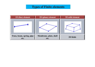
- The different types of analyses that can be done, including 1D, 2D, and 3D analysis
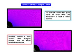
- The types of finite elements that can be used, such as beam, shell, and solid elements
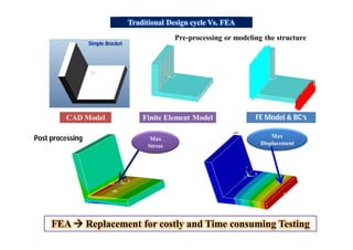
- How FEA can be used as a replacement for physical testing in the design process
- Key steps in pre-processing and post-processing FEA models
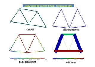
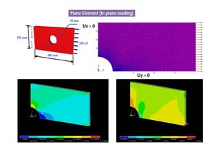
- Examples of how different elements model stresses, including axial, bending, torsional, and plane stresses


![THEORY OF STRUCTURES-I [B. ARCH.]](https://cdn.slidesharecdn.com/ss_thumbnails/theoryofstructures-ib-180903021950-thumbnail.jpg?width=640&height=640&fit=bounds)


