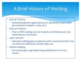
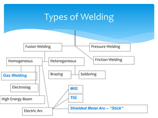
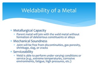
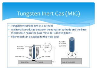
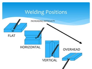
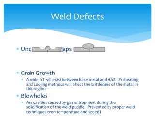
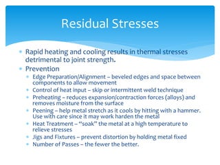
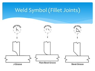
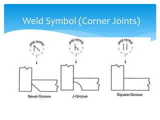
Welding Processes
 Late 19th Century
 Scientists/engineers apply advances in electricity to heat and/or
join metals (Le Chatelier, Joule, etc.)
 Early 20th Century
 Prior to WWI welding was not trusted as a method to join two
metals due to crack issues
 1930’s and 40’s
 Industrial welding gains acceptance and is used extensively in the
war effort to build tanks, aircraft, ships, etc.
 Modern Welding
 the nuclear/space age helps bring welding from an art to a
science
A Brief History of Welding
Types of Welding
Fusion Welding Pressure Welding
Homogeneous Heterogeneous
Brazing SolderingGas Welding
Electroslag
High Energy Beam
Electric Arc
MIG
TIG
Shielded Metal Arc – “Stick”
Friction Welding
 Metallurgical Capacity
 Parent metal will join with the weld metal without
formation of deleterious constituents or alloys
 Mechanical Soundness
 Joint will be free from discontinuities, gas porosity,
shrinkage, slag, or cracks
 Serviceability
 Weld is able to perform under varying conditions or
service (e.g., extreme temperatures, corrosive
environments, fatigue, high pressures, etc.)
Weldability of a Metal
 Base metal is melted
 Filler metal may be added
 Heat is supplied by various means
 Oxyacetylene gas
 Electric Arc
 Plasma Arc
 Laser
Fusion Welding Principles
Fusion Welding
BASE METAL
WELD
SOLIDIFIED SLAG
ARC POOL
WELDING ATMOSPHERE
CORE WIRE
ELECTRODE COATING
ARC STREAM
PENETRATION DEPTH
 During fusion welding, the molten metal in
the weld “puddle” is susceptible to oxidation
 Must protect weld puddle (arc pool) from the
atmosphere
 Methods
 Weld Fluxes
 Inert Gases
 Vacuum
Weld Metal Protection
 Typical fluxes
 SiO2, TiO2, FeO, MgO, Al2O3
 Produces a gaseous shield to prevent contamination
 Act as scavengers to reduce oxides
 Add alloying elements to the weld
 Influence shape of weld bead during solidification
Weld Fluxes
 Argon, helium, nitrogen, and carbon dioxide
 Form a protective envelope around the weld area
 Used in
 MIG
 TIG
 Shield Metal Arc
Inert Gases
 Produce high-quality welds
 Used in electron beam welding
 Nuclear/special metal applications
 Zr, Hf, Ti
 Reduces impurities by a factor of 20 versus other
methods
 Expensive and time-consuming
Vacuum
 Oxyacetylene Cutting/Welding
 Shielded Metal Arc (“Stick”)
 Metal Inert Gas (MIG)
 Tungsten Inert Gas (TIG)
Types of Fusion Welding
 Flame formed by burning a mix of acetylene
(C2H2) and oxygen
 Fusion of metal is achieved by passing the inner
cone of the flame over the metal
 Oxyacetylene can also be used for cutting metals
Oxyacetylene Welding
Inner Cone: 5000-6300 deg F Combustion Envelope 3800 deg
F
2300 deg FTORCH TIP
 An electric arc is generated between a coated
electrode and the parent metal
 The coated electrode carries the electric
current to form the arc, produces a gas to
control the atmosphere and provides filler
metal for the weld bead
 Electric current may be AC or DC. If the
current is DC, the polarity will affect the weld
size and application
Shielded Metal Arc (Stick)
 Process:
 Intense heat at the arc melts the tip of the
electrode
 Tiny drops of metal enter the arc stream and are
deposited on the parent metal
 As molten metal is deposited, a slag forms over the
bead which serves as an insulation against air
contaminants during cooling
 After a weld ‘pass’ is allowed the cool, the oxide
layer is removed by a chipping hammer and then
cleaned with a wirebrush before the next pass.
Shielded Metal Arc (con’t)
 For materials such as Al or Ti which quickly form oxide
layers, a method to place an inert atmosphere around
the weld puddle had to be developed
Inert Gas Welding
 Uses a consumable electrode (filler wire made of the
base metal)
 Inert gas is typically Argon
Metal Inert Gas (MIG)
BASE METAL PUDDLE
POWER
SOURCE
DRIVE WHEELS
CONSUMABLE
ELECTRODE
ARC COLUMNSHIELDING GAS
 Tungsten electrode acts as a cathode
 A plasma is produced between the tungsten cathode and the base
metal which heats the base metal to its melting point
 Filler metal can be added to the weld pool
Tungsten Inert Gas (MIG)
BASE METAL PUDDLE
POWER
SOURCE
ARC COLUMNSHIELDING GAS
TUNGSTEN
ELECTRODE
+ +
BASE METAL (ANODE)
TUNGSTEN
ELECTRODE
(CATHODE)
- - -
+ +
Welding Positions
FLAT
HORIZONTAL
VERTICAL
OVERHEAD
INCREASING DIFFICULTY
 Undercuts/Overlaps
 Grain Growth
 A wide T will exist between base metal and HAZ. Preheating
and cooling methods will affect the brittleness of the metal in
this region
 Blowholes
 Are cavities caused by gas entrapment during the
solidification of the weld puddle. Prevented by proper weld
technique (even temperature and speed)
Weld Defects
 Inclusions
 Impurities or foreign substances which are forced into the weld
puddle during the welding process. Has the same effect as a crack.
Prevented by proper technique/cleanliness.
 Segregation
 Condition where some regions of the metal are enriched with an
alloy ingredient and others aren’t. Can be prevented by proper heat
treatment and cooling.
 Porosity
 The formation of tiny pinholes generated by atmospheric
contamination. Prevented by keeping a protective shield over the
molten weld puddle.
Weld Defects
 Rapid heating and cooling results in thermal stresses
detrimental to joint strength.
 Prevention
 Edge Preparation/Alignment – beveled edges and space between
components to allow movement
 Control of heat input – skip or intermittent weld technique
 Preheating – reduces expansion/contraction forces (alloys) and
removes moisture from the surface
 Peening – help metal stretch as it cools by hitting with a hammer.
Use with care since it may work harden the metal
 Heat Treatment – “soak” the metal at a high temperature to
relieve stresses
 Jigs and Fixtures – prevent distortion by holding metal fixed
 Number of Passes – the fewer the better.
Residual Stresses
Joint Design
BUTT JOINT
STRAP JOINT
LAP JOINT
FILLET JOINT
CORNER JOINT
Generalized Welding Symbol
FAR SIDE DETAILS
ARROW SIDE DETAILS
Field weld symbol
Weld all-around for
pipes, etc.
L1-L2
L1-L2
D = Weld Depth (usually equal to plate thickness)
L1 = Weld Length
L2 = Distance between centers for stitched welds
The Field Weld Symbol is a guide for installation. Shipyards
normally do not use it, except in modular construction.
Electrode
Material
D
D
Weld Geometry
Example Welding Symbol
1/2” 1/2”
1/2
1/2
One-sided welds are max 80% efficient
Two sided are 100% efficient
Geometry symbol for V-groove
Weld Symbols (Butt Joints)
Backing
Weld Symbol (Fillet Joints)
Weld Symbol (Corner Joints)

Welding

  • 1.
  • 2.
     Late 19thCentury  Scientists/engineers apply advances in electricity to heat and/or join metals (Le Chatelier, Joule, etc.)  Early 20th Century  Prior to WWI welding was not trusted as a method to join two metals due to crack issues  1930’s and 40’s  Industrial welding gains acceptance and is used extensively in the war effort to build tanks, aircraft, ships, etc.  Modern Welding  the nuclear/space age helps bring welding from an art to a science A Brief History of Welding
  • 3.
    Types of Welding FusionWelding Pressure Welding Homogeneous Heterogeneous Brazing SolderingGas Welding Electroslag High Energy Beam Electric Arc MIG TIG Shielded Metal Arc – “Stick” Friction Welding
  • 4.
     Metallurgical Capacity Parent metal will join with the weld metal without formation of deleterious constituents or alloys  Mechanical Soundness  Joint will be free from discontinuities, gas porosity, shrinkage, slag, or cracks  Serviceability  Weld is able to perform under varying conditions or service (e.g., extreme temperatures, corrosive environments, fatigue, high pressures, etc.) Weldability of a Metal
  • 5.
     Base metalis melted  Filler metal may be added  Heat is supplied by various means  Oxyacetylene gas  Electric Arc  Plasma Arc  Laser Fusion Welding Principles
  • 6.
    Fusion Welding BASE METAL WELD SOLIDIFIEDSLAG ARC POOL WELDING ATMOSPHERE CORE WIRE ELECTRODE COATING ARC STREAM PENETRATION DEPTH
  • 7.
     During fusionwelding, the molten metal in the weld “puddle” is susceptible to oxidation  Must protect weld puddle (arc pool) from the atmosphere  Methods  Weld Fluxes  Inert Gases  Vacuum Weld Metal Protection
  • 8.
     Typical fluxes SiO2, TiO2, FeO, MgO, Al2O3  Produces a gaseous shield to prevent contamination  Act as scavengers to reduce oxides  Add alloying elements to the weld  Influence shape of weld bead during solidification Weld Fluxes
  • 9.
     Argon, helium,nitrogen, and carbon dioxide  Form a protective envelope around the weld area  Used in  MIG  TIG  Shield Metal Arc Inert Gases
  • 10.
     Produce high-qualitywelds  Used in electron beam welding  Nuclear/special metal applications  Zr, Hf, Ti  Reduces impurities by a factor of 20 versus other methods  Expensive and time-consuming Vacuum
  • 11.
     Oxyacetylene Cutting/Welding Shielded Metal Arc (“Stick”)  Metal Inert Gas (MIG)  Tungsten Inert Gas (TIG) Types of Fusion Welding
  • 12.
     Flame formedby burning a mix of acetylene (C2H2) and oxygen  Fusion of metal is achieved by passing the inner cone of the flame over the metal  Oxyacetylene can also be used for cutting metals Oxyacetylene Welding Inner Cone: 5000-6300 deg F Combustion Envelope 3800 deg F 2300 deg FTORCH TIP
  • 13.
     An electricarc is generated between a coated electrode and the parent metal  The coated electrode carries the electric current to form the arc, produces a gas to control the atmosphere and provides filler metal for the weld bead  Electric current may be AC or DC. If the current is DC, the polarity will affect the weld size and application Shielded Metal Arc (Stick)
  • 14.
     Process:  Intenseheat at the arc melts the tip of the electrode  Tiny drops of metal enter the arc stream and are deposited on the parent metal  As molten metal is deposited, a slag forms over the bead which serves as an insulation against air contaminants during cooling  After a weld ‘pass’ is allowed the cool, the oxide layer is removed by a chipping hammer and then cleaned with a wirebrush before the next pass. Shielded Metal Arc (con’t)
  • 15.
     For materialssuch as Al or Ti which quickly form oxide layers, a method to place an inert atmosphere around the weld puddle had to be developed Inert Gas Welding
  • 16.
     Uses aconsumable electrode (filler wire made of the base metal)  Inert gas is typically Argon Metal Inert Gas (MIG) BASE METAL PUDDLE POWER SOURCE DRIVE WHEELS CONSUMABLE ELECTRODE ARC COLUMNSHIELDING GAS
  • 17.
     Tungsten electrodeacts as a cathode  A plasma is produced between the tungsten cathode and the base metal which heats the base metal to its melting point  Filler metal can be added to the weld pool Tungsten Inert Gas (MIG) BASE METAL PUDDLE POWER SOURCE ARC COLUMNSHIELDING GAS TUNGSTEN ELECTRODE + + BASE METAL (ANODE) TUNGSTEN ELECTRODE (CATHODE) - - - + +
  • 18.
  • 19.
     Undercuts/Overlaps  GrainGrowth  A wide T will exist between base metal and HAZ. Preheating and cooling methods will affect the brittleness of the metal in this region  Blowholes  Are cavities caused by gas entrapment during the solidification of the weld puddle. Prevented by proper weld technique (even temperature and speed) Weld Defects
  • 20.
     Inclusions  Impuritiesor foreign substances which are forced into the weld puddle during the welding process. Has the same effect as a crack. Prevented by proper technique/cleanliness.  Segregation  Condition where some regions of the metal are enriched with an alloy ingredient and others aren’t. Can be prevented by proper heat treatment and cooling.  Porosity  The formation of tiny pinholes generated by atmospheric contamination. Prevented by keeping a protective shield over the molten weld puddle. Weld Defects
  • 21.
     Rapid heatingand cooling results in thermal stresses detrimental to joint strength.  Prevention  Edge Preparation/Alignment – beveled edges and space between components to allow movement  Control of heat input – skip or intermittent weld technique  Preheating – reduces expansion/contraction forces (alloys) and removes moisture from the surface  Peening – help metal stretch as it cools by hitting with a hammer. Use with care since it may work harden the metal  Heat Treatment – “soak” the metal at a high temperature to relieve stresses  Jigs and Fixtures – prevent distortion by holding metal fixed  Number of Passes – the fewer the better. Residual Stresses
  • 22.
    Joint Design BUTT JOINT STRAPJOINT LAP JOINT FILLET JOINT CORNER JOINT
  • 23.
    Generalized Welding Symbol FARSIDE DETAILS ARROW SIDE DETAILS Field weld symbol Weld all-around for pipes, etc. L1-L2 L1-L2 D = Weld Depth (usually equal to plate thickness) L1 = Weld Length L2 = Distance between centers for stitched welds The Field Weld Symbol is a guide for installation. Shipyards normally do not use it, except in modular construction. Electrode Material D D Weld Geometry
  • 24.
    Example Welding Symbol 1/2”1/2” 1/2 1/2 One-sided welds are max 80% efficient Two sided are 100% efficient Geometry symbol for V-groove
  • 25.
    Weld Symbols (ButtJoints) Backing
  • 26.
  • 27.