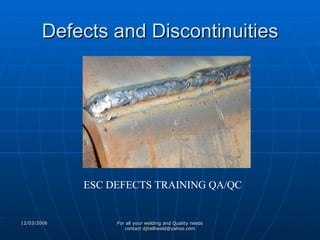
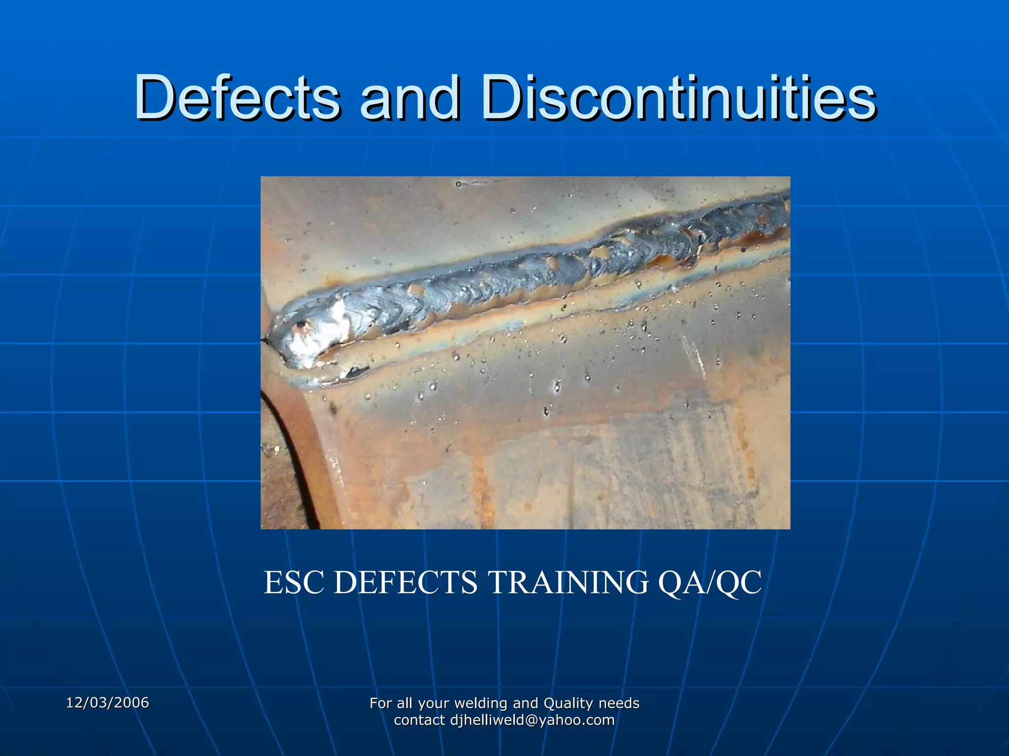
Defects and Discontinuities ESC DEFECTS TRAINING QA/QC
Defect A flaw or flaws that by nature or accumulated effect render a pile or product unable to meet minimum BS EN 288 acceptance standards or specifications. The term designates rejectability. Repair or in very worst situation scrap this should never be an option at ESC it is not cost effective!
Discontinuity An interruption of the typical structure of a material, such as a lack of evenness####### in its mechanical, metallurgical, or physical characteristics. A discontinuity is not necessarily a defect. E.g. To much reinforcement does not require repair it is not cost effective to over weld, but it is less so to repair over weld.
Weld Joint Discontinuities Inclusions Slag Wagon tracks Tungsten   Spatter Arc Craters Cracks Longitudinal Transverse Crater Throat Toe Root Cold or delayed Underbead and Heat-affected zone Hot Misalignment  (hi-lo) Undercut Underfill Concavity or Convexity Excessive reinforcement Improper reinforcement Overlap Burn-through Incomplete or Insufficient Penetration Incomplete Fusion Surface irregularity Overlap Arc Strikes Base Metal Discontinuities Lamellar tearing Laminations and Delaminations Laps and Seams Porosity Uniformly Scattered Cluster Linear Piping Heat-affected zone microstructure alteration Base Plate laminations Size or dimensions
Misalignment  (hi-lo) Definition:  Amount a joint is out of alignment at the root Cause:  Carelessness. Also due to joining different thicknesses (transition thickness) Prevention:  Workmanship. Transition angles not to exceed 2.5 to 1. Repair:  Grinding. Careful on surface finish and direction of grind marks. Inside of Pipe /Tube difficult.
Misalignment
Undercut Definition:  A groove cut at the toe of the weld and left unfilled. Cause:  High amperage, electrode angle, long arc length, rust Prevention:  Set machine on scrap metal to correct parameters. Clean metal before welding. Repair:  Weld with smaller electrode, sometimes must be low hydrogen with preheat. Sometimes must gouge first.
Undercut   Undercut typically has an allowable limit. Different codes and standards vary greatly in the allowable amount. Plate - the lesser of 0.8mm or 5% (norm) ESC EN BS288 allows up to 1mm anything deeper than this must be repaired!
Under Cut
Insufficient Fill or Under fill Definition: The weld surface is below the adjacent surfaces of the base metal  Cause: Improper welding techniques Prevention: Apply proper welding techniques for the weld type and position. Use stripper beads before the cover pass. Repair: Simply weld to fill. May require preparation by grinding.
Under fill
Insufficient Fill on the Root Side (suckback) Definition: The weld surface is below the adjacent surfaces of the base metal at the weld root. Cause: Typically improper joint preparation or excessive weld pool heat. Prevention: Correct cause. (see next slide) Repair: Backweld to fill. May requireremoval of weld section by grinding for access to the joint root.
Cause for Insufficient Fill at the Root Some liquids, like water or molten steel, try to cover as much surface area of whatever they are in contact with as possible. Welding a root pass too wide can also cause the bead to sag (overhead position).
 
 
Removing a root pass by grinding 1. Recreate the groove geometry as closely as possible. 2. Use a saw or die grinder and 1/16 - 1/8” cut off wheel to recreate root opening. Remember repairs are sometimes required to be made with a smaller electrode. 3. Open the groove angle. Be careful to leave the proper root face dimension.  4. Feather the start and stop to blend smoothly into and out of the existing weld.
 
Excessive Concavity or Convexity Definition:  Concavity or convexity of a fillet weld which exceeds the specified allowable limits  Cause:  Amperage and travel speed Prevention:  Observe proper parameters and techniques. Repair:  Grind off or weld on. Must blend smoothly into the base metal.
Concavity
Root Concavity
Convexity
Reinforcement Excessive  Insufficient  Improper contour The amount of a groove weld which extends beyond the surface of the plate Face Reinforcement Root Reinforcement
Excessive Reinforcement Definition: Specifically defined by the standard. Typically, Reinforcement should be flush to 1/16”(pipe) or flush to 1/8” (plate or structural shapes).  Cause: Travel speed too slow, amperage too low Prevention: Set amperage and travel speed on scrap plate. Repair: Remove excessive reinforcement and feather the weld toes to a smooth transition to the base plate.
Excessive Penetration
Definition: Specifically defined by the standard. Typically, Underfill may be up to 5% of metal thickness not to exceed 1/32” as long as the thickness is made up in the opposite reinforcement. Not applied to fillet welds. Cause: On root reinforcement - Too little filler metal will cause thinning of the filler metal. In OH position, too hot or too wide will cause drooping of the open root puddle. Prevention: Use proper welding technique. Use backing or consumable inserts. Use back weld or backing.  Repair: Possibly simply increase the face reinforcement. If backwelding is not possible, must remove and reweld. Insufficient Reinforcement
Definition: When the weld exhibits less than a 135 0  transition angle at the weld toe. Cause: Poor welding technique Prevention: Use proper techniques. A weave or whip motion can often eliminate the problem. Repair: The weld face must be feathered into the base plate. 135 0 Improper Weld Contour
Overlap Definition: When the face of the weld extends beyond the toe of the weld Cause: Improper welding technique. Typically, electrode angles and travel speed.  Prevention: Overlap is a contour problem. Proper welding technique will prevent this problem. Repair: Overlap must be removed to blend smoothly into the base metal. Be careful of deep grind marks that run transverse to the load. Also be careful of fusion discontinuities hidden by grinding. Use NDT to be sure.
Overlap Overlap is measured with a square edge such as a 6” rule. No amount of overlap is typically allowed.
Burn-through  (non-standard) Definition: When an undesirable open hole has been completely melted through the base metal. The hole may or may not be left open. Cause: Excessive heat input. Prevention: Reduce heat input by increasing travel speed, use of a heat sink, or by reducing welding parameters. Repair: Will be defined by standards. Filling may suffice. Otherwise, removal and rewelding may be required. Some standards may require special filler metal and/or PWHT.
Incomplete or Insufficient Penetration Definition: When the weld metal does not extend to the required depth into the joint root Cause: Low amperage, low preheat, tight root opening, fast travel speed, short arc length. Prevention: Correct the contributing factor(s). Repair: Back gouge and back weld or remove and reweld.
ICP
Incomplete Fusion Definition: Where weld metal does not form a cohesive bond with the base metal. Cause: Low amperage, steep electrode angles, fast travel speed, short arc gap, lack of preheat, electrode too small, unclean base metal, arc off seam. Prevention: Eliminate the potential causes. Repair: remove and reweld, being careful to completely remove the defective area. This is sometimes extremely difficult to find.
Lack of Side Wall Fusion
Arc Strike Definition: A localized coalescence outside the weld zone. Cause: Carelessness Prevention: In difficult areas, adjacent areas can be protected using fire blankets. Repair: Where applicable, arc strikes must be sanded smooth and tested for cracks. If found, they must be remove and repaired using a qualified repair procedure and inspected as any other weld.
Arc Strike
Weld Spatter Causes Prevention High arc power Reduce arc power Magnetic arc blow Reduce arc length or switch to AC power Incorrect settings for GMAW process Modify electrical settings (but be careful to maintain full fusion Damp electrodes Use dry electrodes
Inclusions Slag Wagontracks Tungsten
Definition: Slag entrapped within the weld Cause: Low amperage, improper technique, Trying to weld in an area that is too tight.  Slow travel in Vertical Down Prevention: Increase amperage or preheat, grind out tight areas to gain access to bottom of joint.  Repair: Remove by grinding. Reweld. Slag Inclusion
Slag Inclusion
Definition: Slang term for a groove left at the toe of a root pass which becomes filled with slag and is trapped in the weld. Cause: The contour of the root pass is too high, or the weld toe is not bonded to the base metal Prevention: Use proper technique to deposit the weld root. Repair: Best repaired before applying the hot pass. Carefully grind the root pass face flat. be careful not to gouge other areas on the weldment. Wagon Tracks  (non-standard)
Definition: A tungsten particle embedded in a weld. (Typically GTAW only) Cause: Tungsten electrode too small, amperage too high, AC balance on +, Upslope too high, electrode tip not snipped, electrode dipped into the weld pool or touched with the fill rod, electrode split. Prevention: Eliminate the cause Repair: Grind out and reweld Tungsten Inclusion
Inclusions fix when you see it. otherwise grind out & fix
Whiskers Unsightly Inhibits material flow in piping Are inclusions Can break off in pipes and damage equipment downline
Spatter Definition: Small particles of weld metal expelled from the welding operation which adhere to the base metal surface.  Cause: Long arc length, severe electrode angles, high amperages. Prevention: Correct the cause. Base metal can be protected with coverings or hi-temp paints. Repair: Remove by grinding or sanding. Sometimes must be tested as if it were a weld.
Arc Craters Definition: A depression left at the termination of the weld where the weld pool is left unfilled. Cause: Improper weld termination techniques Prevention: Repair: If no cracks exist, simply fill in the crater. Generally welding from beyond the crater back into the crater.
Cracks Longitudinal Transverse Crater Throat Toe Root Underbead and Heat-affected zone Hot Cold or delayed
Definition: A crack running in the direction of the weld axis. May be found in the weld or base metal. Cause: Preheat or fast cooling problem. Also caused by shrinkage stresses in high constraint areas. Prevention: Weld toward areas of less constraint. Also preheat to even out the cooling rates. Repair: Remove and reweld Longitudinal Crack
Definition: A crack running into or inside a weld, transverse to the weld axis direction. Cause: Weld metal hardness problem Prevention: Minimize heat input and monitor interpass temperature max 200 c Repair: Dependant on specification and matterial Transverse Crack
Definition: A crack, generally in the shape of an “X” which is found in a crater. Crater cracks are hot cracks. Cause: The center of the weld pool becomes solid before the outside of the weld pool, pulling the center apart during cooling Prevention: Use crater fill, fill the crater at weld termination and/or preheat to even out the cooling of the puddle Repair: Crater Crack
Definition: A longitudinal crack located in the weld throat area. Cause: Transverse Stresses, probably from shrinkage. Indicates inadequate filler metal selection or welding procedure. May be due to crater crack propagation. Prevention: Correct initial cause. Increasing preheat may prevent it. be sure not to leave a crater. Use a more ductile filler material. Repair: Remove and reweld using appropriate procedure. Be sure to correct initial problem first. Throat Crack
Definition: A crack in the base metal beginning at the toe of the weld Cause: Transverse shrinkage stresses. Indicates a HAZ brittleness problem. Prevention: Increase preheat if possible, or use a more ductile filler material. Repair:  Toe Crack
Toe Crack
Definition: A crack in the weld at the weld root. Cause: Transverse shrinkage stresses. Same as a throat crack.  Prevention: Same as a throat crack Repair: Root Crack
Root Crack
Definition: A crack in the unmelted parent metal of the HAZ. Cause:  Hydrogen embrittlement Prevention: Use Lo/Hi electrodes and/or preheat Repair: (only found using NDT).  Remove and reweld. Underbead Crack
Definition: A crack in the weld that occurs during solidification. Cause: Micro stresses from weld metal shrinkage pulling apart weld metal as it cools from liquid to solid temp. Prevention: Preheat or use a low tensil filler material. Repair: Hot Crack
Definition: A crack that occurs after the metal has completely solidified Cause: Shrinkage, Highly restrained welds, Discontinuities Prevention: Preheat, weld toward areas of less constraint, use a more ductile weld metal Repair: Remove and reweld, correct problem first, preheat may be necessary. Cold Crack
Cold Crack or Weld Metal Hydrogen Crack
Repairs to Cracks Determine the cause Correct the problem Take precautions to prevent reoccurrence Generally required to repair using a smaller electrode
Base Metal Discontinuities Lamellar tearing Laminations and Delaminations Laps and Seams
Lamellar Tearing
Laminations Base Metal Discontinuity May require repair prior to welding Formed during the milling process
Lamination effects can be reduced by joint design:
Laps and Seams A mill-induced discontinuity in which results from a lump of metal being squeezed over into the surface of the material.  If beyond acceptable limits, must be removed and repaired or discarded.
Porosity Single Pore Uniformly Scattered Cluster Linear Piping
Porosity
Single Pore Separated by at least their own diameter along the axis of the weld
Uniformly Scattered Porosity Typically judged by diameter and proximity to a start or stop often caused by low amperage or short arc gap or an unshielded weld start
Cluster Porosity Typically viewed as a single large discontinuity
Linear Porosity being linear greatly affects the severity of this discontinuity
Piping Porosity Generally has special allowable limits
Porosity  preheat will help eliminate may need an electrode with more deoxidizers Use run-on/run-off taps restart on top of previous weld and grind off lump
Heat-affected zone microstructure alteration add drawing of HAZ of groove weld with leaders to: grain refinement grain growth hardened areas softened areas precipitate suseptable areas.
Size or dimension If it renders the part unusable, it is a defect. If it is outside the allowable limit, it renders the part unusable. Things don’t have to be perfect, just within the acceptable tolerance. Working to perfection is too time consuming and costly
Hammer marks Stress risers Unsightly Unnecessary
REPAIR TECHNIQUES May involve: different process different procedure different preheat/PWHT different electrode smaller electrode
Only repair defects. Discontinuities are by definition  acceptable. Repair is therefore unnecessary and not cost effective.

Welding Defects

  • 1.
    Defects and DiscontinuitiesESC DEFECTS TRAINING QA/QC
  • 2.
    Defect A flawor flaws that by nature or accumulated effect render a pile or product unable to meet minimum BS EN 288 acceptance standards or specifications. The term designates rejectability. Repair or in very worst situation scrap this should never be an option at ESC it is not cost effective!
  • 3.
    Discontinuity An interruptionof the typical structure of a material, such as a lack of evenness####### in its mechanical, metallurgical, or physical characteristics. A discontinuity is not necessarily a defect. E.g. To much reinforcement does not require repair it is not cost effective to over weld, but it is less so to repair over weld.
  • 4.
    Weld Joint DiscontinuitiesInclusions Slag Wagon tracks Tungsten Spatter Arc Craters Cracks Longitudinal Transverse Crater Throat Toe Root Cold or delayed Underbead and Heat-affected zone Hot Misalignment (hi-lo) Undercut Underfill Concavity or Convexity Excessive reinforcement Improper reinforcement Overlap Burn-through Incomplete or Insufficient Penetration Incomplete Fusion Surface irregularity Overlap Arc Strikes Base Metal Discontinuities Lamellar tearing Laminations and Delaminations Laps and Seams Porosity Uniformly Scattered Cluster Linear Piping Heat-affected zone microstructure alteration Base Plate laminations Size or dimensions
  • 5.
    Misalignment (hi-lo)Definition: Amount a joint is out of alignment at the root Cause: Carelessness. Also due to joining different thicknesses (transition thickness) Prevention: Workmanship. Transition angles not to exceed 2.5 to 1. Repair: Grinding. Careful on surface finish and direction of grind marks. Inside of Pipe /Tube difficult.
  • 6.
  • 7.
    Undercut Definition: A groove cut at the toe of the weld and left unfilled. Cause: High amperage, electrode angle, long arc length, rust Prevention: Set machine on scrap metal to correct parameters. Clean metal before welding. Repair: Weld with smaller electrode, sometimes must be low hydrogen with preheat. Sometimes must gouge first.
  • 8.
    Undercut Undercut typically has an allowable limit. Different codes and standards vary greatly in the allowable amount. Plate - the lesser of 0.8mm or 5% (norm) ESC EN BS288 allows up to 1mm anything deeper than this must be repaired!
  • 9.
  • 10.
    Insufficient Fill orUnder fill Definition: The weld surface is below the adjacent surfaces of the base metal Cause: Improper welding techniques Prevention: Apply proper welding techniques for the weld type and position. Use stripper beads before the cover pass. Repair: Simply weld to fill. May require preparation by grinding.
  • 11.
  • 12.
    Insufficient Fill onthe Root Side (suckback) Definition: The weld surface is below the adjacent surfaces of the base metal at the weld root. Cause: Typically improper joint preparation or excessive weld pool heat. Prevention: Correct cause. (see next slide) Repair: Backweld to fill. May requireremoval of weld section by grinding for access to the joint root.
  • 13.
    Cause for InsufficientFill at the Root Some liquids, like water or molten steel, try to cover as much surface area of whatever they are in contact with as possible. Welding a root pass too wide can also cause the bead to sag (overhead position).
  • 14.
  • 15.
  • 16.
    Removing a rootpass by grinding 1. Recreate the groove geometry as closely as possible. 2. Use a saw or die grinder and 1/16 - 1/8” cut off wheel to recreate root opening. Remember repairs are sometimes required to be made with a smaller electrode. 3. Open the groove angle. Be careful to leave the proper root face dimension. 4. Feather the start and stop to blend smoothly into and out of the existing weld.
  • 17.
  • 18.
    Excessive Concavity orConvexity Definition: Concavity or convexity of a fillet weld which exceeds the specified allowable limits Cause: Amperage and travel speed Prevention: Observe proper parameters and techniques. Repair: Grind off or weld on. Must blend smoothly into the base metal.
  • 19.
  • 20.
  • 21.
  • 22.
    Reinforcement Excessive Insufficient Improper contour The amount of a groove weld which extends beyond the surface of the plate Face Reinforcement Root Reinforcement
  • 23.
    Excessive Reinforcement Definition:Specifically defined by the standard. Typically, Reinforcement should be flush to 1/16”(pipe) or flush to 1/8” (plate or structural shapes). Cause: Travel speed too slow, amperage too low Prevention: Set amperage and travel speed on scrap plate. Repair: Remove excessive reinforcement and feather the weld toes to a smooth transition to the base plate.
  • 24.
  • 25.
    Definition: Specifically definedby the standard. Typically, Underfill may be up to 5% of metal thickness not to exceed 1/32” as long as the thickness is made up in the opposite reinforcement. Not applied to fillet welds. Cause: On root reinforcement - Too little filler metal will cause thinning of the filler metal. In OH position, too hot or too wide will cause drooping of the open root puddle. Prevention: Use proper welding technique. Use backing or consumable inserts. Use back weld or backing. Repair: Possibly simply increase the face reinforcement. If backwelding is not possible, must remove and reweld. Insufficient Reinforcement
  • 26.
    Definition: When theweld exhibits less than a 135 0 transition angle at the weld toe. Cause: Poor welding technique Prevention: Use proper techniques. A weave or whip motion can often eliminate the problem. Repair: The weld face must be feathered into the base plate. 135 0 Improper Weld Contour
  • 27.
    Overlap Definition: Whenthe face of the weld extends beyond the toe of the weld Cause: Improper welding technique. Typically, electrode angles and travel speed. Prevention: Overlap is a contour problem. Proper welding technique will prevent this problem. Repair: Overlap must be removed to blend smoothly into the base metal. Be careful of deep grind marks that run transverse to the load. Also be careful of fusion discontinuities hidden by grinding. Use NDT to be sure.
  • 28.
    Overlap Overlap ismeasured with a square edge such as a 6” rule. No amount of overlap is typically allowed.
  • 29.
    Burn-through (non-standard)Definition: When an undesirable open hole has been completely melted through the base metal. The hole may or may not be left open. Cause: Excessive heat input. Prevention: Reduce heat input by increasing travel speed, use of a heat sink, or by reducing welding parameters. Repair: Will be defined by standards. Filling may suffice. Otherwise, removal and rewelding may be required. Some standards may require special filler metal and/or PWHT.
  • 30.
    Incomplete or InsufficientPenetration Definition: When the weld metal does not extend to the required depth into the joint root Cause: Low amperage, low preheat, tight root opening, fast travel speed, short arc length. Prevention: Correct the contributing factor(s). Repair: Back gouge and back weld or remove and reweld.
  • 31.
  • 32.
    Incomplete Fusion Definition:Where weld metal does not form a cohesive bond with the base metal. Cause: Low amperage, steep electrode angles, fast travel speed, short arc gap, lack of preheat, electrode too small, unclean base metal, arc off seam. Prevention: Eliminate the potential causes. Repair: remove and reweld, being careful to completely remove the defective area. This is sometimes extremely difficult to find.
  • 33.
    Lack of SideWall Fusion
  • 34.
    Arc Strike Definition:A localized coalescence outside the weld zone. Cause: Carelessness Prevention: In difficult areas, adjacent areas can be protected using fire blankets. Repair: Where applicable, arc strikes must be sanded smooth and tested for cracks. If found, they must be remove and repaired using a qualified repair procedure and inspected as any other weld.
  • 35.
  • 36.
    Weld Spatter CausesPrevention High arc power Reduce arc power Magnetic arc blow Reduce arc length or switch to AC power Incorrect settings for GMAW process Modify electrical settings (but be careful to maintain full fusion Damp electrodes Use dry electrodes
  • 37.
  • 38.
    Definition: Slag entrappedwithin the weld Cause: Low amperage, improper technique, Trying to weld in an area that is too tight. Slow travel in Vertical Down Prevention: Increase amperage or preheat, grind out tight areas to gain access to bottom of joint. Repair: Remove by grinding. Reweld. Slag Inclusion
  • 39.
  • 40.
    Definition: Slang termfor a groove left at the toe of a root pass which becomes filled with slag and is trapped in the weld. Cause: The contour of the root pass is too high, or the weld toe is not bonded to the base metal Prevention: Use proper technique to deposit the weld root. Repair: Best repaired before applying the hot pass. Carefully grind the root pass face flat. be careful not to gouge other areas on the weldment. Wagon Tracks (non-standard)
  • 41.
    Definition: A tungstenparticle embedded in a weld. (Typically GTAW only) Cause: Tungsten electrode too small, amperage too high, AC balance on +, Upslope too high, electrode tip not snipped, electrode dipped into the weld pool or touched with the fill rod, electrode split. Prevention: Eliminate the cause Repair: Grind out and reweld Tungsten Inclusion
  • 42.
    Inclusions fix whenyou see it. otherwise grind out & fix
  • 43.
    Whiskers Unsightly Inhibitsmaterial flow in piping Are inclusions Can break off in pipes and damage equipment downline
  • 44.
    Spatter Definition: Smallparticles of weld metal expelled from the welding operation which adhere to the base metal surface. Cause: Long arc length, severe electrode angles, high amperages. Prevention: Correct the cause. Base metal can be protected with coverings or hi-temp paints. Repair: Remove by grinding or sanding. Sometimes must be tested as if it were a weld.
  • 45.
    Arc Craters Definition:A depression left at the termination of the weld where the weld pool is left unfilled. Cause: Improper weld termination techniques Prevention: Repair: If no cracks exist, simply fill in the crater. Generally welding from beyond the crater back into the crater.
  • 46.
    Cracks Longitudinal TransverseCrater Throat Toe Root Underbead and Heat-affected zone Hot Cold or delayed
  • 47.
    Definition: A crackrunning in the direction of the weld axis. May be found in the weld or base metal. Cause: Preheat or fast cooling problem. Also caused by shrinkage stresses in high constraint areas. Prevention: Weld toward areas of less constraint. Also preheat to even out the cooling rates. Repair: Remove and reweld Longitudinal Crack
  • 48.
    Definition: A crackrunning into or inside a weld, transverse to the weld axis direction. Cause: Weld metal hardness problem Prevention: Minimize heat input and monitor interpass temperature max 200 c Repair: Dependant on specification and matterial Transverse Crack
  • 49.
    Definition: A crack,generally in the shape of an “X” which is found in a crater. Crater cracks are hot cracks. Cause: The center of the weld pool becomes solid before the outside of the weld pool, pulling the center apart during cooling Prevention: Use crater fill, fill the crater at weld termination and/or preheat to even out the cooling of the puddle Repair: Crater Crack
  • 50.
    Definition: A longitudinalcrack located in the weld throat area. Cause: Transverse Stresses, probably from shrinkage. Indicates inadequate filler metal selection or welding procedure. May be due to crater crack propagation. Prevention: Correct initial cause. Increasing preheat may prevent it. be sure not to leave a crater. Use a more ductile filler material. Repair: Remove and reweld using appropriate procedure. Be sure to correct initial problem first. Throat Crack
  • 51.
    Definition: A crackin the base metal beginning at the toe of the weld Cause: Transverse shrinkage stresses. Indicates a HAZ brittleness problem. Prevention: Increase preheat if possible, or use a more ductile filler material. Repair: Toe Crack
  • 52.
  • 53.
    Definition: A crackin the weld at the weld root. Cause: Transverse shrinkage stresses. Same as a throat crack. Prevention: Same as a throat crack Repair: Root Crack
  • 54.
  • 55.
    Definition: A crackin the unmelted parent metal of the HAZ. Cause: Hydrogen embrittlement Prevention: Use Lo/Hi electrodes and/or preheat Repair: (only found using NDT). Remove and reweld. Underbead Crack
  • 56.
    Definition: A crackin the weld that occurs during solidification. Cause: Micro stresses from weld metal shrinkage pulling apart weld metal as it cools from liquid to solid temp. Prevention: Preheat or use a low tensil filler material. Repair: Hot Crack
  • 57.
    Definition: A crackthat occurs after the metal has completely solidified Cause: Shrinkage, Highly restrained welds, Discontinuities Prevention: Preheat, weld toward areas of less constraint, use a more ductile weld metal Repair: Remove and reweld, correct problem first, preheat may be necessary. Cold Crack
  • 58.
    Cold Crack orWeld Metal Hydrogen Crack
  • 59.
    Repairs to CracksDetermine the cause Correct the problem Take precautions to prevent reoccurrence Generally required to repair using a smaller electrode
  • 60.
    Base Metal DiscontinuitiesLamellar tearing Laminations and Delaminations Laps and Seams
  • 61.
  • 62.
    Laminations Base MetalDiscontinuity May require repair prior to welding Formed during the milling process
  • 63.
    Lamination effects canbe reduced by joint design:
  • 64.
    Laps and SeamsA mill-induced discontinuity in which results from a lump of metal being squeezed over into the surface of the material. If beyond acceptable limits, must be removed and repaired or discarded.
  • 65.
    Porosity Single PoreUniformly Scattered Cluster Linear Piping
  • 66.
  • 67.
    Single Pore Separatedby at least their own diameter along the axis of the weld
  • 68.
    Uniformly Scattered PorosityTypically judged by diameter and proximity to a start or stop often caused by low amperage or short arc gap or an unshielded weld start
  • 69.
    Cluster Porosity Typicallyviewed as a single large discontinuity
  • 70.
    Linear Porosity beinglinear greatly affects the severity of this discontinuity
  • 71.
    Piping Porosity Generallyhas special allowable limits
  • 72.
    Porosity preheatwill help eliminate may need an electrode with more deoxidizers Use run-on/run-off taps restart on top of previous weld and grind off lump
  • 73.
    Heat-affected zone microstructurealteration add drawing of HAZ of groove weld with leaders to: grain refinement grain growth hardened areas softened areas precipitate suseptable areas.
  • 74.
    Size or dimensionIf it renders the part unusable, it is a defect. If it is outside the allowable limit, it renders the part unusable. Things don’t have to be perfect, just within the acceptable tolerance. Working to perfection is too time consuming and costly
  • 75.
    Hammer marks Stressrisers Unsightly Unnecessary
  • 76.
    REPAIR TECHNIQUES Mayinvolve: different process different procedure different preheat/PWHT different electrode smaller electrode
  • 77.
    Only repair defects.Discontinuities are by definition acceptable. Repair is therefore unnecessary and not cost effective.

Editor's Notes

  • #4 Maybe have picture of over reinforced but weld
  • #6 Carelessness = lazyness just sounds less aggressive? WORKMANSHIP= STUPID ####
  • #7 Explain about dogs and wedges and how to remove and repair!! If the weld is 100% pen no worries apart from ugly!!
  • #8 Reinforce about the correct settings!! The ER70S-6 has high silicon because Malaysia only uses co2 whish needs more deoxidants.
  • #13 This needs to be explained for on site bridge abutments