Downloaded 895 times


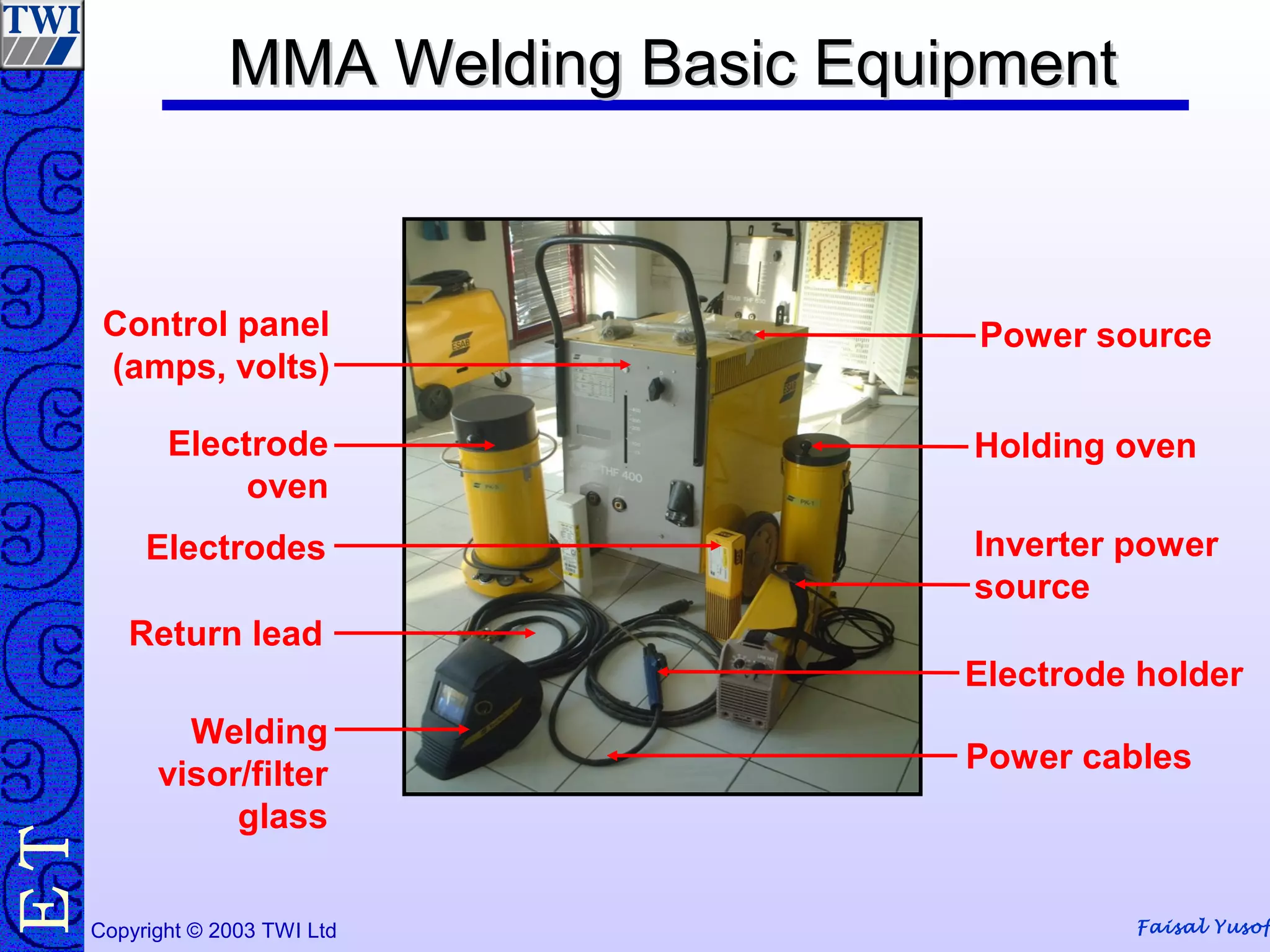


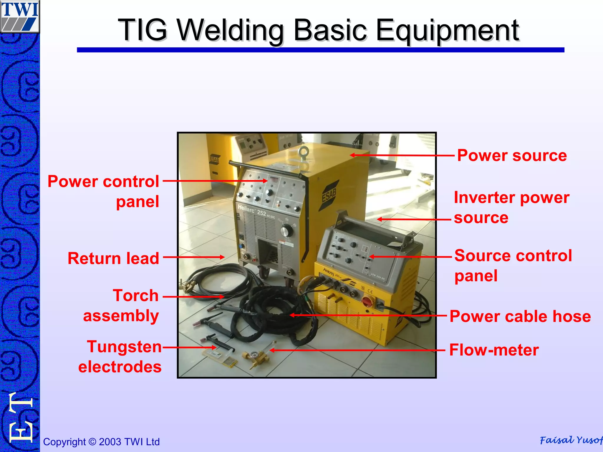

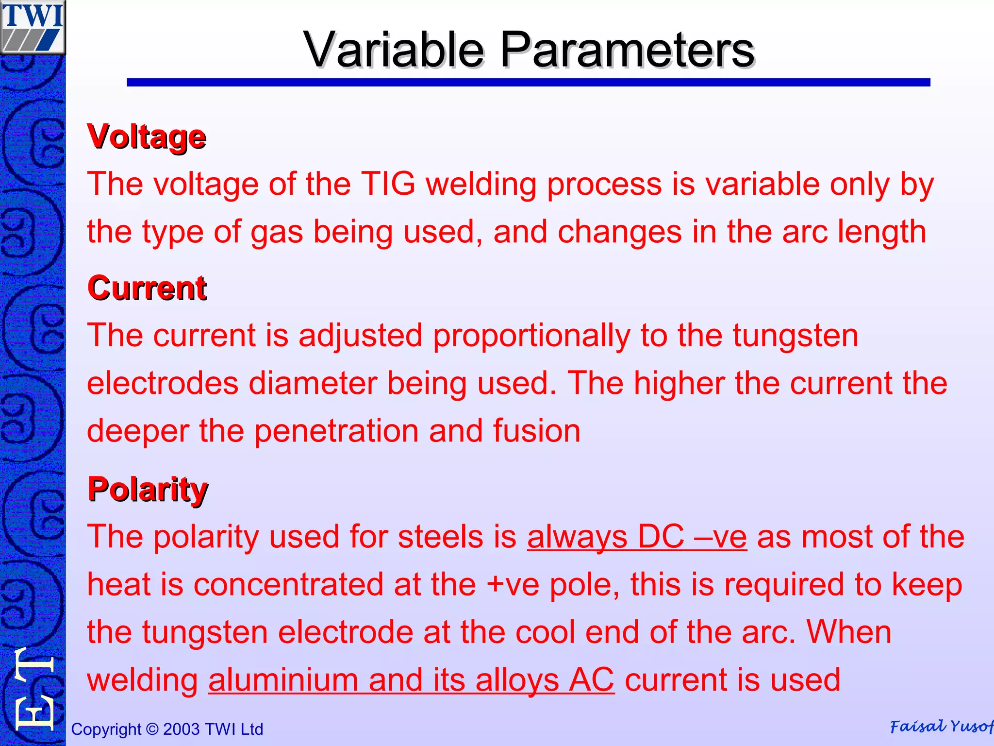
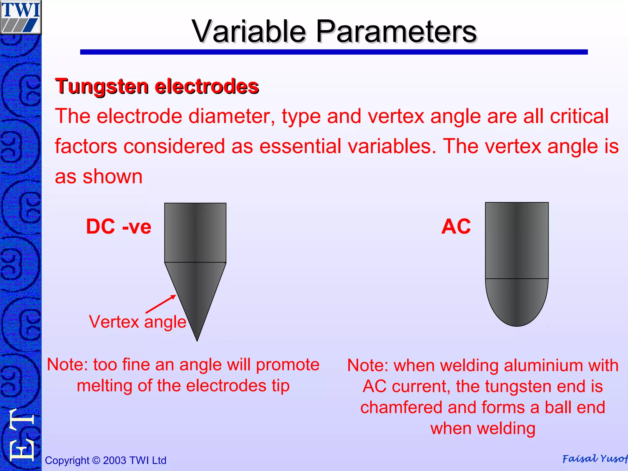


This document provides information on manual metal arc welding (MMA) and tungsten inert gas (TIG) welding processes. For MMA welding, it discusses electrode types, equipment, parameters like current and polarity, welding techniques, and advantages/disadvantages. For TIG welding, it describes the basic equipment, parameters including voltage, current, polarity and gas type/flow rate, torch components, techniques, and pros and cons. Safety considerations are also covered for both processes.


![Coded Agents – with UiPath SDK + LangGraph [Virtual Hands-on Workshop]](https://cdn.slidesharecdn.com/ss_thumbnails/codedagentsdeck-251215155422-5497c599-thumbnail.jpg?width=640&height=640&fit=bounds)


