Download as PDF, PPTX


![ Software-in-the-loop (all digitally simulated)
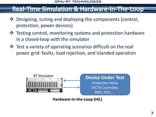
Hardware-in-the-loop
Projects
Real-Time Simulation of Phasor Measurement Unit
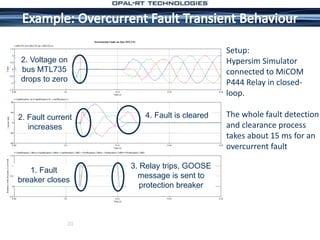
Emulation of an Over-Current Relay
Model Developed in SimPowerSystems (MATLAB/Simulink)
Real-Time Simulation on OPAL-RT Simulator
Validated with actual relay (SEL-487E) in HIL setup and comparison
with Stand Alone Testing System
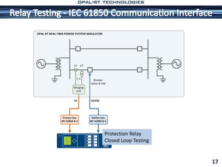
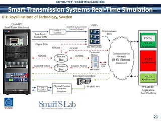
Power System Communication (Station & Process Bus
Implementation)- Real-Time HIL Setup [Opal-RT + ABB-RED 670]
PMU in HIL setup with development of graphical monitoring
interface
22](https://image.slidesharecdn.com/opalrtmodernpowersystems2013-140819145500-phpapp01/85/OPAL-RT-Modern-power-systems-22-320.jpg)
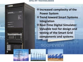

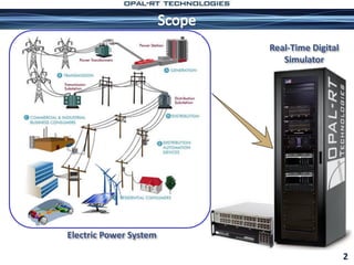
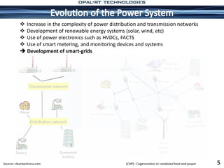
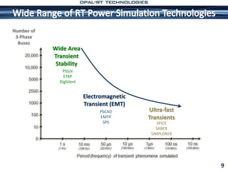
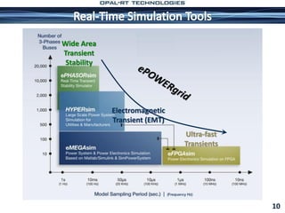
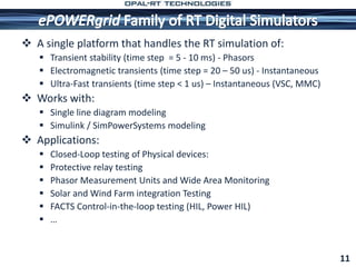
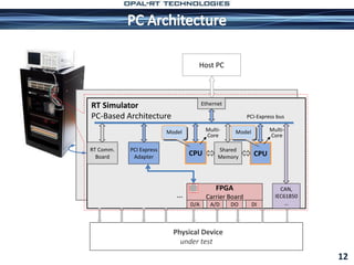
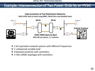
The document discusses the impact of decarbonization and increased electricity demands on electric power systems, emphasizing the need for real-time digital simulators to handle the complexities of modern power generation and distribution. It outlines applications of these simulators in testing various scenarios, such as control system validation and the integration of renewable energy sources. The paper highlights the role of smart grids and Hardware-in-the-Loop (HIL) testing in ensuring efficient and reliable power system operations.


![[Juan Martinez] Transient Analysis of Power Systems.pdf](https://cdn.slidesharecdn.com/ss_thumbnails/juanmartineztransientanalysisofpowersystems-220712220132-46430ea1-thumbnail.jpg?width=640&height=640&fit=bounds)