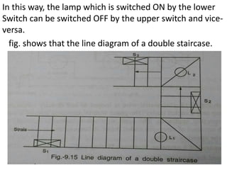
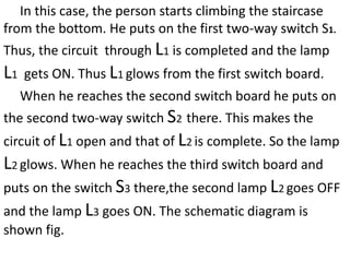
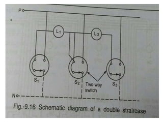
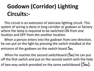
Simple control circuits in
domestic installations:-
For domestic appliances, Single-phase, 230V, 50Hz a.c.
supply is available. Lighting circuits and power circuits are
separately controlled. Lighting circuit consists of lamp, fan
and devices upto 5A. On the other hand, power circuit
mainly consists of loads which have more than 5A i.e. 15A
capacity. In this section, we will discuss the simple control
circuit for lighting purpose.
Control of one Lamp from
one point:-
Fig. indicates the control circuit of single lamp operated
from single point or switch.
In this case, the phase wire and neutral are made
available at the lamp terminals.
Phase wire is taken through single pole single throw
(SPST) switch and neutral is directly connected to the
lamp terminal.
Switch must be connected in the phase wire and never
in the neutral wire. Similarly the fuse is always connected
in the phase wire and not in the neutral wire. This
provides more safety to the operator. If the switch is
provided in the neutral, there is a potential between the
live wire and the earth, even with the switch in the off
position. This would cause the shock to the operator
repairing the lighting points with the switch in the off
position. If the switch is in the phase wire then open (off)
position of the switch makes the entire circuit dead and
the operator does not get the shock while repairing the
lighiting points with the switch in the off position.
Two way control of Lamps or
Staircase Wiring
The circuit used for staircase lighiting is shown in fig.
In this case, there are two two-way switches used. The
first two-way switch S1 is placed near the first step of the
staircase. The other two-way switch S2 is placed at the
upper storey where the stairs end. The light point is
provided at an adequate height between the first and last
stairs.
As shown in fig. when the two-way switch S1 is moved
from position 2 to 3,the lamp gets connected between
the phase and the neutral and thus glows. Path is P – (1-
3) – (1-2) – lamp.
Having reached the top of the staircase where S2 is
installed, the switch S2 is moved from 1 to 3. Thus,the
circuit through the lamp gets broken. The circuit is open
and hence the lamp becomes OFF> The circuit path P –
(1-3) – 1 only.
In this way, the lamp which is switched ON by the lower
Switch can be switched OFF by the upper switch and vice-
versa.
fig. shows that the line diagram of a double staircase.
In this case, the person starts climbing the staircase
from the bottom. He puts on the first two-way switch S1.
Thus, the circuit through L1 is completed and the lamp
L1 gets ON. Thus L1 glows from the first switch board.
When he reaches the second switch board he puts on
the second two-way switch S2 there. This makes the
circuit of L1 open and that of L2 is complete. So the lamp
L2 glows. When he reaches the third switch board and
puts on the switch S3 there,the second lamp L2 goes OFF
and the lamp L3 goes ON. The schematic diagram is
shown fig.
Godown (Corridor) Lighting
Circuits:-
This circuit is an extension of staircase lighting circuit. This
system of wiring is done in long corridor or godown or factory
where the lamp is required to be switched ON from one
location and OFF from the another location.
When a person enters into the godown from one direction,
he can put on the light by pressing the switch installed at the
entrance of the godown on the switch board SB1.
When he reaches the second switchboard (SB2) he can put
off the first switch and put on the second switch with the help
of two-way switch provided on the same switchboard (SB2).
Again when he reaches the third switchboard (SB3), he
can put off the previous light (L2) by a switch 2 and switch
on the next lamp by switch 1 installed on the same
switchboard (SB3).This process can be repeated so long as
it is required.
Fig. shows the schematic diagram of godown wiring.
From the schematic diagram, it can be seen that there are
2 two-way switches on the switchboarda SB2,SB3,SB4.
While moving in the godown, he can put lamp L1 by
operating the first two-way switch on the switch board SB1.
When he reaches the switchboards SB2, he can operate
the two-way switch 1 on SB2. Thus lamp L2 will be connected
between the phase and neutral and will become ON.L1 can be
brought to OFF by operating the two-way switch 2 on sB2.
Again when he reaches the switchboards SB3, he can
operate the switch 2 on SB3 to put L2 OFF and operate L3 by
operating the switch 1 on SB3 and so on.

Simple control circuits in domestic installations,ppt,eee

  • 1.
    Simple control circuitsin domestic installations:- For domestic appliances, Single-phase, 230V, 50Hz a.c. supply is available. Lighting circuits and power circuits are separately controlled. Lighting circuit consists of lamp, fan and devices upto 5A. On the other hand, power circuit mainly consists of loads which have more than 5A i.e. 15A capacity. In this section, we will discuss the simple control circuit for lighting purpose.
  • 2.
    Control of oneLamp from one point:- Fig. indicates the control circuit of single lamp operated from single point or switch.
  • 3.
    In this case,the phase wire and neutral are made available at the lamp terminals. Phase wire is taken through single pole single throw (SPST) switch and neutral is directly connected to the lamp terminal. Switch must be connected in the phase wire and never in the neutral wire. Similarly the fuse is always connected in the phase wire and not in the neutral wire. This provides more safety to the operator. If the switch is provided in the neutral, there is a potential between the live wire and the earth, even with the switch in the off position. This would cause the shock to the operator repairing the lighting points with the switch in the off position. If the switch is in the phase wire then open (off) position of the switch makes the entire circuit dead and the operator does not get the shock while repairing the lighiting points with the switch in the off position.
  • 4.
    Two way controlof Lamps or Staircase Wiring The circuit used for staircase lighiting is shown in fig.
  • 5.
    In this case,there are two two-way switches used. The first two-way switch S1 is placed near the first step of the staircase. The other two-way switch S2 is placed at the upper storey where the stairs end. The light point is provided at an adequate height between the first and last stairs. As shown in fig. when the two-way switch S1 is moved from position 2 to 3,the lamp gets connected between the phase and the neutral and thus glows. Path is P – (1- 3) – (1-2) – lamp. Having reached the top of the staircase where S2 is installed, the switch S2 is moved from 1 to 3. Thus,the circuit through the lamp gets broken. The circuit is open and hence the lamp becomes OFF> The circuit path P – (1-3) – 1 only.
  • 6.
    In this way,the lamp which is switched ON by the lower Switch can be switched OFF by the upper switch and vice- versa. fig. shows that the line diagram of a double staircase.
  • 7.
    In this case,the person starts climbing the staircase from the bottom. He puts on the first two-way switch S1. Thus, the circuit through L1 is completed and the lamp L1 gets ON. Thus L1 glows from the first switch board. When he reaches the second switch board he puts on the second two-way switch S2 there. This makes the circuit of L1 open and that of L2 is complete. So the lamp L2 glows. When he reaches the third switch board and puts on the switch S3 there,the second lamp L2 goes OFF and the lamp L3 goes ON. The schematic diagram is shown fig.
  • 9.
    Godown (Corridor) Lighting Circuits:- Thiscircuit is an extension of staircase lighting circuit. This system of wiring is done in long corridor or godown or factory where the lamp is required to be switched ON from one location and OFF from the another location. When a person enters into the godown from one direction, he can put on the light by pressing the switch installed at the entrance of the godown on the switch board SB1. When he reaches the second switchboard (SB2) he can put off the first switch and put on the second switch with the help of two-way switch provided on the same switchboard (SB2).
  • 10.
    Again when hereaches the third switchboard (SB3), he can put off the previous light (L2) by a switch 2 and switch on the next lamp by switch 1 installed on the same switchboard (SB3).This process can be repeated so long as it is required. Fig. shows the schematic diagram of godown wiring.
  • 12.
    From the schematicdiagram, it can be seen that there are 2 two-way switches on the switchboarda SB2,SB3,SB4. While moving in the godown, he can put lamp L1 by operating the first two-way switch on the switch board SB1. When he reaches the switchboards SB2, he can operate the two-way switch 1 on SB2. Thus lamp L2 will be connected between the phase and neutral and will become ON.L1 can be brought to OFF by operating the two-way switch 2 on sB2. Again when he reaches the switchboards SB3, he can operate the switch 2 on SB3 to put L2 OFF and operate L3 by operating the switch 1 on SB3 and so on.