Download as PDF, PPTX
![mGrid Controller HIL - 31
ERL 25 November 2015
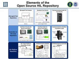
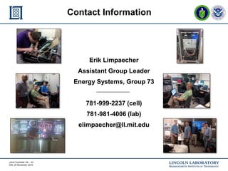
Demonstration against ORNL/EPRI
Microgrid Functional Use Cases
[UPDATE]
Functional Use Case Description Demonstration
F-1 Frequency Control Selection of grid-forming, -feeding,
and -supporting energy sources to
maintain stability; sub-second
control to maintain stable
frequency while islanded
The microgrid controller selects from
among the two gensets and battery
DERs.
F-2 Voltage Control Regulate voltage at the microgrid
point of common coupling
No demo
F-3 Intentional Islanding Planned disconnect from area
electric power system (AEPS)
Islanding will be initiated by the
microgrid controller
F-4 Unintentional Islanding Fast disconnect from AEPS upon
large disturbance to provide
continuous supply to loads
No demo due to battery and PV
inverter controller PLL instability
F-5 Transition from Islanded to
Grid-tied
Resynchronize and reconnect to
AEPS
Initiated by microgrid controller once
generators and grid synchronize](https://image.slidesharecdn.com/microgridcontrollerhildemonstrationplatformv16afinal-160111134911/85/Microgrid-Controller-HIL-Demonstration-Platform-31-320.jpg)
![mGrid Controller HIL - 32
ERL 25 November 2015
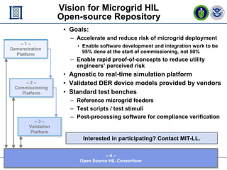
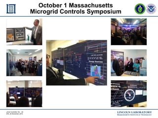
Demonstration against ORNL/EPRI
Microgrid Functional Use Cases (cont.)
[UPDATE]
Functional Use Case Description Demonstration
F-6(a) Energy Management: grid-
tied
Coordinate generation, load, &
storage dispatch, to participate in
utility operation and energy market
activities
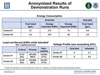
The microgrid controllers target a
power export value for a defined
period, and should also shave peak
demand.
F-6(b) Energy Management:
islanded
Coordinate generation, load, &
storage dispatch, to optimize
islanded operation (fuel
consumption, islanding duration)
Fuel consumption and service of
critical and priority loads are
measured during islanded operation.
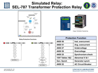
F-7 Microgrid Protection Configure protection devices for
different operating conditions
DER and relay protection are
implemented, but are not
configurable.
F-8 Ancillary Services:
regulation
Provide frequency regulation,
generation reserves, reactive
power support, and demand
response to AEPS
Demand response to hit a target
power export value;
Reactive power support to maintain
unity power factor at PCC
F-9 Microgrid Blackstart Restore islanded operation after a
complete shutdown
Likely limited by present genset
control capabilities
F-10 User Interface, Data
Collection
Organize, archive, and visualize
real-time and non-real-time data
Data collection and visualization
performed by MIT-LL, not mC](https://image.slidesharecdn.com/microgridcontrollerhildemonstrationplatformv16afinal-160111134911/85/Microgrid-Controller-HIL-Demonstration-Platform-32-320.jpg)
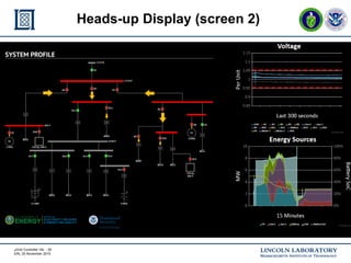

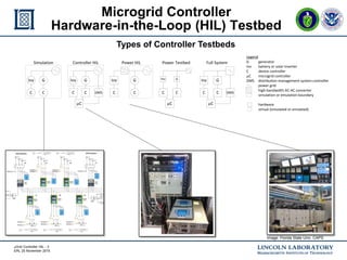
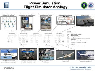
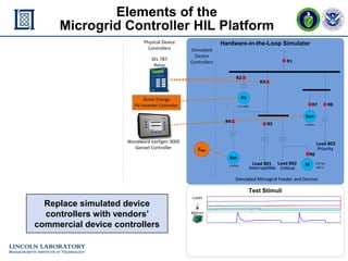
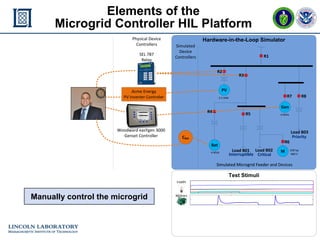
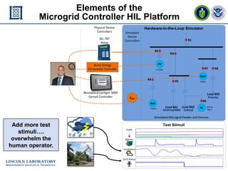
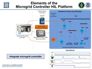
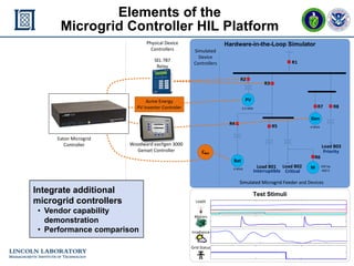
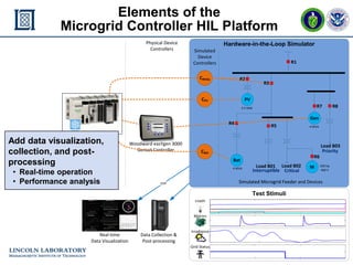
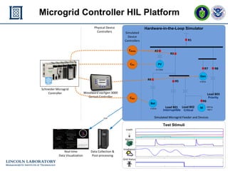
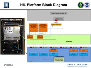
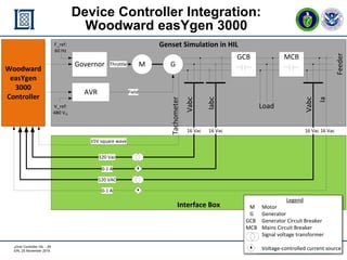
This document describes a microgrid controller hardware-in-the-loop (HIL) test platform that can be used to test microgrid controllers in a simulated environment before deployment. The platform uses real-time simulation and hardware devices to model a microgrid test feeder and distributed energy resources. It allows integration and testing of various commercial microgrid controllers to validate their performance under different operating conditions and stimuli in a controlled, low-risk environment.