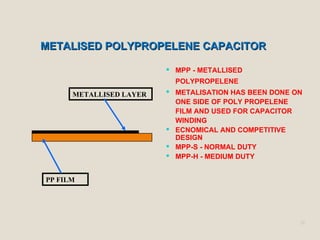
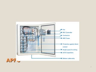
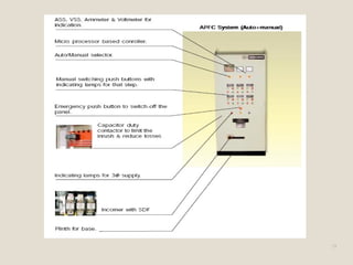
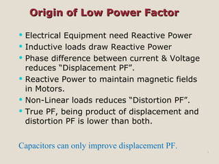
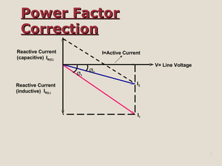
Power factor is the ratio of active power to apparent power. Low power factors are caused by inductive loads and non-linear loads which result in inefficient energy use and overloading of electrical equipment. Automatic power factor correction (APFC) systems automatically switch capacitor banks to maintain a target power factor under varying loads without manual intervention. Proper selection of capacitors, switching equipment, and harmonic filters is required when implementing APFC to prevent overloading and resonance issues.

![8
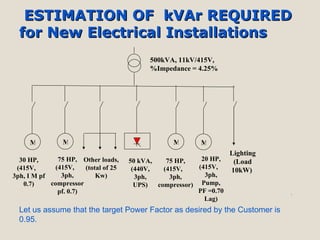
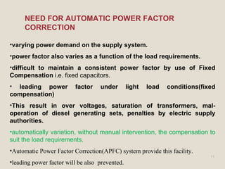
Kvar For The Supply Transformer-
For 500 kVA transformer, kVAr = 30 kVAr
Kvar For Induction Motor-
rating of motor = 200 HP x 0.746
= 150 kW
Kvar for motor = 150*[tan(cos-1
(0.95)- tan(cos-1
(0.99)]
= 104 Kvar
Kvar For UPS-
rating of UPS = 50 KVA* 0.7
= 35 Kw
Kvar for UPS = 35 [tan(cos-1
(0.70)- tan(cos-1
(0.99)]
= 25 Kvar
Kvar For Others & lighting load-
Kvar for UPS = 24 [tan(cos-1
(0.70)- tan(cos-1
(0.99)]
= 17 Kvar
Total kvar requirement = (30+104+35+25+17)kvar =211 Kvar
Assuming 15% design assumption and contigency = 221*0.15=31.65 Kvar
Total kvar = 242.65 kvar
Kavr recommended= 250 kvar
Capacitor req. (c) = Qc/V2
(2πf)
Hence Capacitor req. for UPF=106
*250/(2302
*100π)
= 150.51µF.](https://image.slidesharecdn.com/apfcpanel-191222142037/85/Apfc-panel-8-320.jpg)
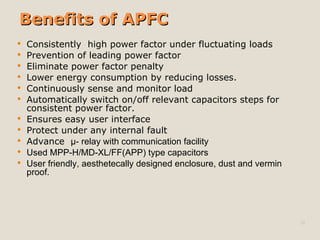
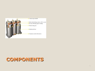
![Specification of capacitors in APFCSpecification of capacitors in APFC
Qkvar
Degree Of Protection IP20
Ambient temperature
Voltage rise should be≤ 3.0% [% Vc = (Q kvar
*%X)/(kva)]
Voltage rise due to series reactor and harmonics
Size of individual capacitor banks (step requirement)
Directly connected Discharge Device(Resistor, VT)
to discharge the capacitor to reduce voltage to 50
volts within one minute
16](https://image.slidesharecdn.com/apfcpanel-191222142037/85/Apfc-panel-16-320.jpg)