This document provides an overview of a senior design project to create a prototype wireless body area network (WBAN) consisting of a custom body sensor unit (BSU) and an Android-based body control unit (BCU). The BSU hardware prototype measures motion data from an accelerometer and gyroscope, timestamps the data, transmits it to the BCU via Bluetooth, and stores 30 minutes of data locally. The BCU is an Android phone running a custom app that receives the data, stores 8 hours of data locally, and allows the user to view the data. The project aimed to design compact, lightweight, long-lasting devices to monitor patients and help reduce healthcare costs through remote monitoring.


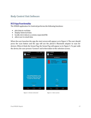
![Final WBAN Report 7
modem; its modular capabilities; and the attached SMA port, which allows for
interchangeable 2.4GHz antennas per the request of Dr. Li.
In order to stay within specified volume, integrated technologies are important. The
MPU6050 Breakout Board meets all four previously mentioned requirements and is
compatible with the chosen microcontroller. Its use of the MPU6050 combines a 3-channel
gyroscope and a 3-channel accelerometer onto a single silicon die together with an
onboard Digital Motion Processor and eliminates the need for two separate gyroscope and
accelerometer sensors. In effect, the combination of these sensors reduces size and cost by
removing the need to purchase separate components. The implementation of the chip onto
a breakout board introduces further modularity of design and use while the low operating
voltage satisfies the calculated power constraints of the project.
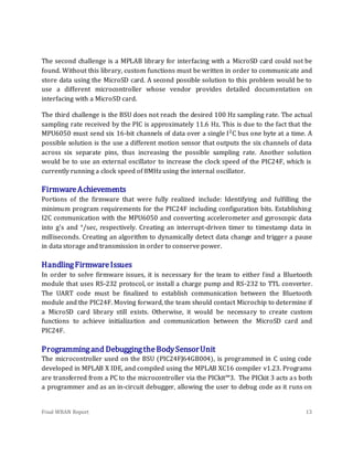
One of the overall project specifications is that the device locally stores at least 30 minutes
of time-stamped motion data. As seen in the calculations below, any external on-board
storage device must have a storage capacity of at least 2.4 MB. By taking into consideration
the design constraints, it is apparent that the storage device must be small, low energy
consuming, and capable of holding greater than 2.4 MB. Because today’s manufacturers
don’t make secure digital cards any smaller than 4GB, the removable Apacer 4GB MicroSD
Card is the cheapest, most reliable choice and possesses a sufficient theoretical storage
capacity of over 800 hours of data.
Equation 1:
{(
6 channel
sample
∗
16 bits
channel
) + (
18 bits
timestamp
)} ∗ [
60 seconds
minute
∗ 30 minutes ∗
100 samples
second
]
= 20,520,000 bits =̃ 2.5MB
Equation 2:
4GB ∗ [
1024MB
1GB
∗
30 minutes
2.5MB
∗
1 hour
60 minutes
] ≅ 800 hours
Due to discrepancies between nominal voltages and actual voltages, in addition to
variations in voltage levels, a rechargeable power source with an output above that of our
component with the largest operating voltage is essential. The 3.6V lithium-ion](https://image.slidesharecdn.com/977cf260-bfcd-4411-826c-f9b6c8546dc9-150710203920-lva1-app6892/85/WBAN-11-320.jpg)


![Final WBAN Report 19
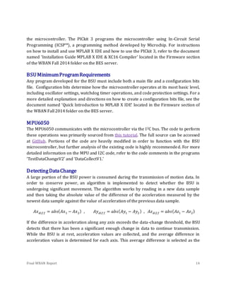
public void onItemSelected(AdapterView<?> parent, View view,
int pos, long id) {
// An item was selected. You can retrieve the selected item
using
// parent.getItemAtPosition(pos)
selected = parent.getItemAtPosition(pos).toString();
if (selected.equals("Accelerometer")){
RTPlot.setTitle("Accelerometer");
RTPlot.setRangeLabel("Acceleration (G)");
}
else if (selected.equals("Gyroscope")){
RTPlot.setTitle("Gyroscope");
RTPlot.setRangeLabel("Deg/s");
}
}
void updatePlot(String uuidStr, dataPoint point) {
double[] d = point.getDatac();
if (selected.equals("Accelerometer")){
for (int i = 0; i < 3; i++) {
RTSeries[i].addFirst(null, d[i]);
}
}
else if (selected.equals("Gyroscope")){
for (int i = 0; i < 3; i++) {
RTSeries[i].addFirst(null, d[i+3]);](https://image.slidesharecdn.com/977cf260-bfcd-4411-826c-f9b6c8546dc9-150710203920-lva1-app6892/85/WBAN-23-320.jpg)
![Final WBAN Report 20
}
}
as well as in res/values/strings.xml
<!-- populate the spinner list -->
<string-array name="sensor_array">
<item>Accelerometer</item>
<item>Gyroscope</item>
</string-array>
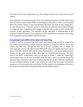
ReceivingData
The following code shows how data is received in DeviceActivity.java. The data is pulled in
from BluetoothLeService as an EXTRA. It is then put in a byte array called value along with
three other “dummy” values that are meant to simulate an additional sensor. The current
time is then found and then both the data and timestamp are stored together as a dataPoint
object. The convert() method is then called, which converts the raw value into G’s (Note
that this conversion factor will be different when using a sensor other than the sensorTag).
The updatePlot and saveData methods are then called.
byte[] tmp =
intent.getByteArrayExtra(BluetoothLeService.EXTRA_DATA);
// 64, 0, -64 are dummy data for an additional sensor
byte[] value = {tmp[0], tmp[1], tmp[2], 64, 0, -64};
r = value.length;
Date date1 = getTimeStamp();
dataPoint myPoint = new dataPoint(value, date1);
myPoint.convert();
updatePlot(uuidStr, myPoint);](https://image.slidesharecdn.com/977cf260-bfcd-4411-826c-f9b6c8546dc9-150710203920-lva1-app6892/85/WBAN-24-320.jpg)
![Final WBAN Report 21
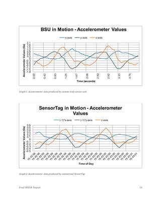
saveData(myPoint);
SavingData
Saving data is done with the saveData method, which initilizes a CSVWriter object and
writes the current sensor sample to a comma-separated file called ‘wbandata.csv’. This
method also adds the current sample to a list object so that it can be retrieved quickly when
the user wants to display historical data.
PlottingData
Plots are created using the library Androidplot. The code for the real time plot and the
history plot is in res/layout/plot.xml along with the other UI widgets. Plotting is done with
the updatePlot method, which takes the current data point and adds it to RTSeries.
RTSeries is an object that stores data and it is associated with RTPlot as shown in the
following code:
RTSeries[0] = new SimpleXYSeries("X");
RTSeries[1] = new SimpleXYSeries("Y");
RTSeries[2] = new SimpleXYSeries("Z");
RTPlot.addSeries(RTSeries[0],
new LineAndPointFormatter(Color.rgb(200,0,0),Color.rgb(100,0,0),
null, null));
RTPlot.addSeries(RTSeries[1],
new LineAndPointFormatter(Color.rgb(0,200,0),Color.rgb(0,100,0),
null, null));
RTPlot.addSeries(RTSeries[2],
new LineAndPointFormatter(Color.rgb(0,0,200),Color.rgb(0,0,100),
null, null));
Most of the WBAN app’s action takes place within DeviceActivity.java, as opposed to being
split up logically between several activities. This is done by setting the visibility of UI
elements to VISIBLE or INVISIBLE depending on whether they should be displayed.](https://image.slidesharecdn.com/977cf260-bfcd-4411-826c-f9b6c8546dc9-150710203920-lva1-app6892/85/WBAN-25-320.jpg)


