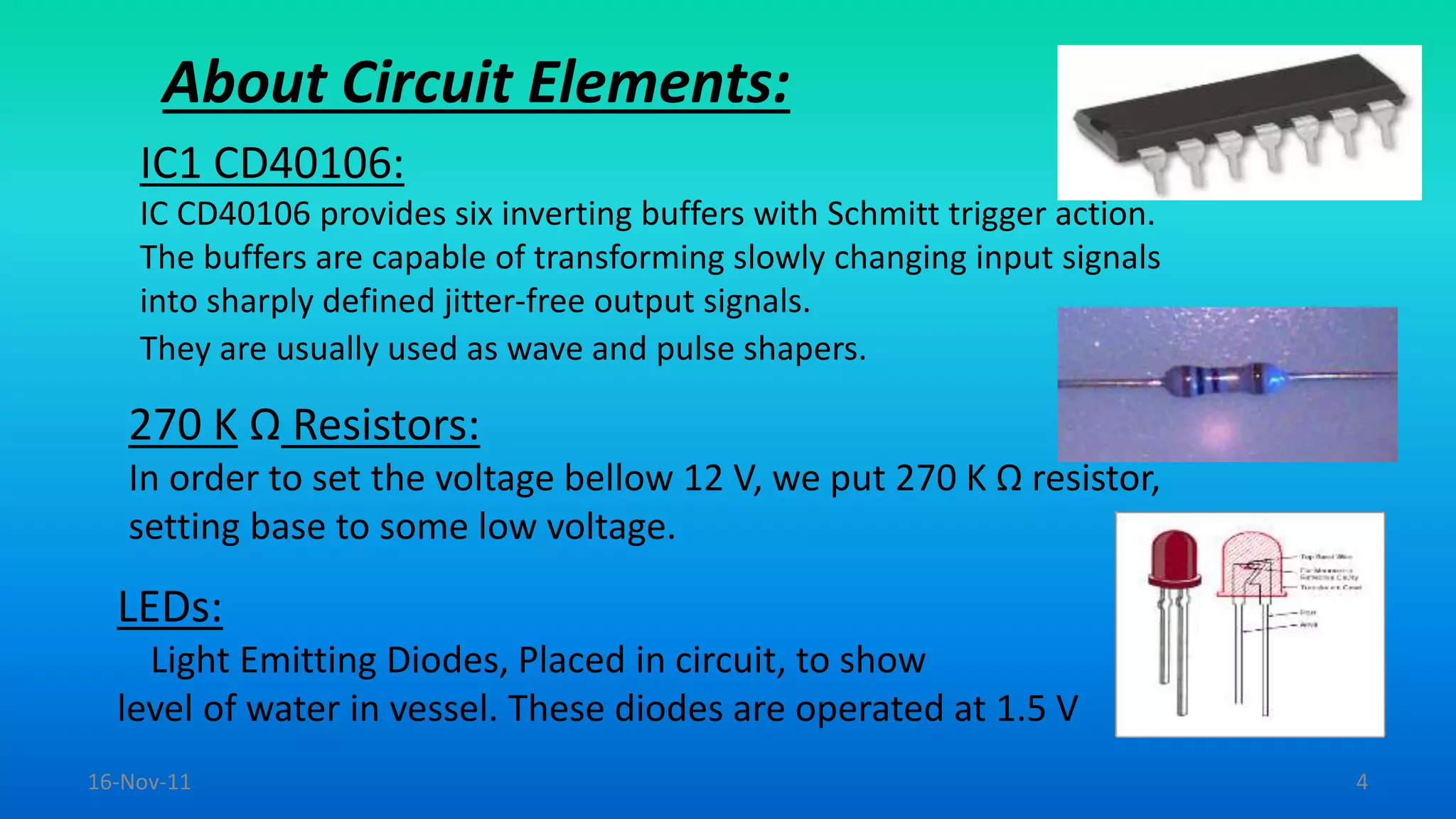
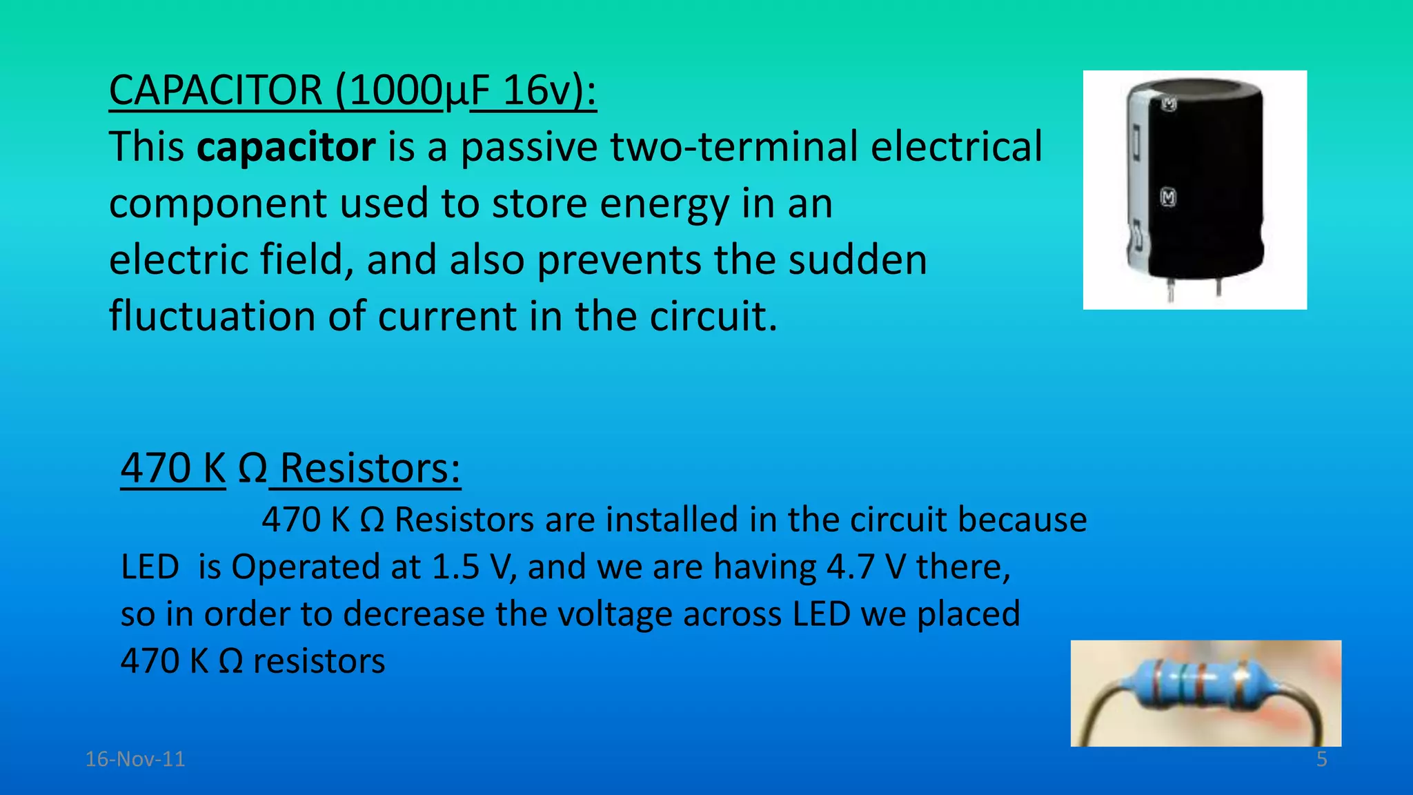
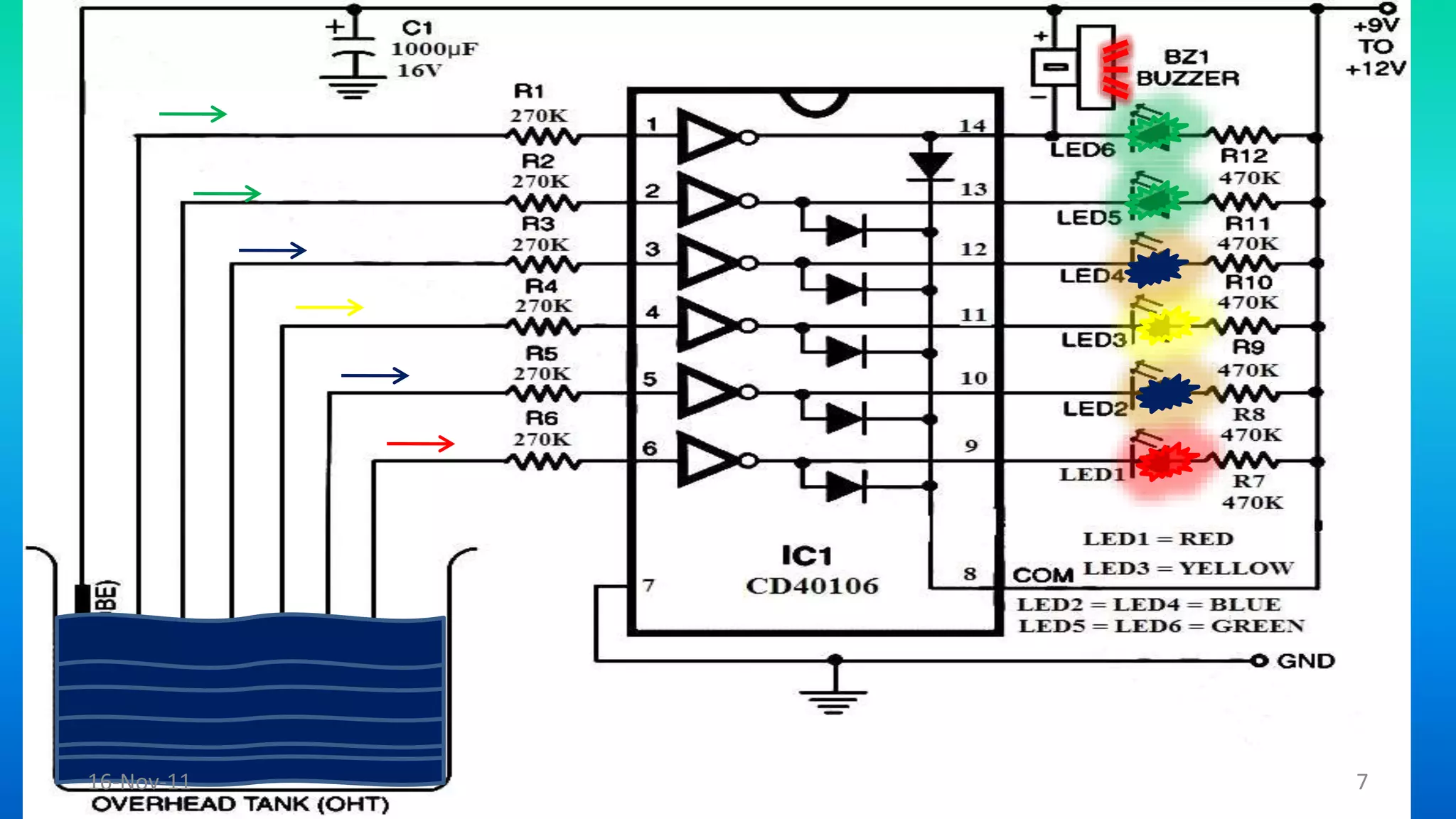
A presentation by:
Sajeed Mahaboob
2011ME1111
Guided by:
Dr. Ranjana Sodhi
16-Nov-11 1
Introduction:
This circuit is designed to indicate the level of water in
any type of vessel (tank) to prevent the over flow of
water and many other uses.
As the water level increases from the base of the tank, the number
of glowing LEDs with different colors increases subsequently.
Amount of water present in a water tank can be easily measured.
16-Nov-11 2
Components List:
Circuit elements used are as follow:
IC1 CD40106.
470 K Ω Resistor.
270 K Ω Resistor.
Sound Buzzer.
Capacitor 1000 µF 16V.
Battery (9V).
LEDs 2Red,2Green,1Yellow,2Blue.
14 Pin IC Socket.16-Nov-11 3
About Circuit Elements:
IC1 CD40106:
IC CD40106 provides six inverting buffers with Schmitt trigger action.
The buffers are capable of transforming slowly changing input signals
into sharply defined jitter-free output signals.
They are usually used as wave and pulse shapers.
270 K Ω Resistors:
In order to set the voltage bellow 12 V, we put 270 K Ω resistor,
setting base to some low voltage.
LEDs:
Light Emitting Diodes, Placed in circuit, to show
level of water in vessel. These diodes are operated at 1.5 V
16-Nov-11 4
CAPACITOR (1000µF 16v):
This capacitor is a passive two-terminal electrical
component used to store energy in an
electric field, and also prevents the sudden
fluctuation of current in the circuit.
470 K Ω Resistors:
470 K Ω Resistors are installed in the circuit because
LED is Operated at 1.5 V, and we are having 4.7 V there,
so in order to decrease the voltage across LED we placed
470 K Ω resistors
16-Nov-11 5
Working of Circuit:
• When any wire is dipped in water that wire will be
connected to wire N (common probe) through water,
establishing a negative voltage across the base of diode.
Current begins to flow from circuit. In this way, LED
glows.
• After successive connections of wires with N,
respective LEDs will glow, and when wire F will be
connected to N , then there will be sound alarming you
that water has attained maximum level and after this
water will flow over.16-Nov-11 6
16-Nov-11 7
Applications of Circuit:
This Circuit has a number of practical uses in daily life.
Now the circuit is ready to indicate the level of water in tank.
Can be used to measure underground storage of water.
This water level Indicator works to maintain a constant water
level.
Alarm starts ringing as soon as tank becomes full.
It helps to check overflow and wastage of water
by warning the person when the vessel is about to brim.
It can also be used to calculate incoming and out going water
in large reservoirs also.
It is used to predict the arrival of floods.16-Nov-11 8

Water Level Indicator (Mini project)

  • 1.
    A presentation by: SajeedMahaboob 2011ME1111 Guided by: Dr. Ranjana Sodhi 16-Nov-11 1
  • 2.
    Introduction: This circuit isdesigned to indicate the level of water in any type of vessel (tank) to prevent the over flow of water and many other uses. As the water level increases from the base of the tank, the number of glowing LEDs with different colors increases subsequently. Amount of water present in a water tank can be easily measured. 16-Nov-11 2
  • 3.
    Components List: Circuit elementsused are as follow: IC1 CD40106. 470 K Ω Resistor. 270 K Ω Resistor. Sound Buzzer. Capacitor 1000 µF 16V. Battery (9V). LEDs 2Red,2Green,1Yellow,2Blue. 14 Pin IC Socket.16-Nov-11 3
  • 4.
    About Circuit Elements: IC1CD40106: IC CD40106 provides six inverting buffers with Schmitt trigger action. The buffers are capable of transforming slowly changing input signals into sharply defined jitter-free output signals. They are usually used as wave and pulse shapers. 270 K Ω Resistors: In order to set the voltage bellow 12 V, we put 270 K Ω resistor, setting base to some low voltage. LEDs: Light Emitting Diodes, Placed in circuit, to show level of water in vessel. These diodes are operated at 1.5 V 16-Nov-11 4
  • 5.
    CAPACITOR (1000µF 16v): Thiscapacitor is a passive two-terminal electrical component used to store energy in an electric field, and also prevents the sudden fluctuation of current in the circuit. 470 K Ω Resistors: 470 K Ω Resistors are installed in the circuit because LED is Operated at 1.5 V, and we are having 4.7 V there, so in order to decrease the voltage across LED we placed 470 K Ω resistors 16-Nov-11 5
  • 6.
    Working of Circuit: •When any wire is dipped in water that wire will be connected to wire N (common probe) through water, establishing a negative voltage across the base of diode. Current begins to flow from circuit. In this way, LED glows. • After successive connections of wires with N, respective LEDs will glow, and when wire F will be connected to N , then there will be sound alarming you that water has attained maximum level and after this water will flow over.16-Nov-11 6
  • 7.
  • 8.
    Applications of Circuit: ThisCircuit has a number of practical uses in daily life. Now the circuit is ready to indicate the level of water in tank. Can be used to measure underground storage of water. This water level Indicator works to maintain a constant water level. Alarm starts ringing as soon as tank becomes full. It helps to check overflow and wastage of water by warning the person when the vessel is about to brim. It can also be used to calculate incoming and out going water in large reservoirs also. It is used to predict the arrival of floods.16-Nov-11 8