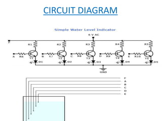
ELECTRON DEVICES MINI 
PROJECT 
WATER LEVEL INDICATOR 
BY:- 
L RAGHAV SAI 
M VENKAT SAI 
SIVA REDDY
COMPONENTS REQUIRED 
• TRANSISTORS(2N222) 
• RESISTORS(22K,2.2K) 
• LEDS(3) 
• AC TRANSFORMER
CIRCUIT DIAGRAM
WORKING 
• Transistor acting as a switch is the basic 
application of this experiment. 
• The areas for transistors to act as a switch are in 
its cut off region (off state) and saturation region 
(on state). 
• In cut off region the input and base are grounded. 
• Base emitter junction is reverse biased and base 
collector is also reverse biased. 
• No collector current flows.
• In saturation region input and base are given 
some voltage. 
• Base emitter junction is forward biased and 
base collector is also forward biased. 
• When the BRASS strip touches the water level 
the base gets the current and the led glows up 
and the water level is indicated.
THE END

Water level indicator -MINI PROJECT

  • 1.
    ELECTRON DEVICES MINI PROJECT WATER LEVEL INDICATOR BY:- L RAGHAV SAI M VENKAT SAI SIVA REDDY
  • 2.
    COMPONENTS REQUIRED •TRANSISTORS(2N222) • RESISTORS(22K,2.2K) • LEDS(3) • AC TRANSFORMER
  • 3.
  • 4.
    WORKING • Transistoracting as a switch is the basic application of this experiment. • The areas for transistors to act as a switch are in its cut off region (off state) and saturation region (on state). • In cut off region the input and base are grounded. • Base emitter junction is reverse biased and base collector is also reverse biased. • No collector current flows.
  • 5.
    • In saturationregion input and base are given some voltage. • Base emitter junction is forward biased and base collector is also forward biased. • When the BRASS strip touches the water level the base gets the current and the led glows up and the water level is indicated.
  • 6.