Downloaded 478 times


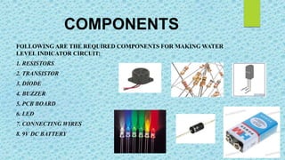
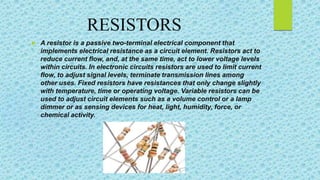


The document describes a water level indicator project aimed at detecting and indicating the water level in overhead tanks to prevent overflow and save resources. It details the components used, such as resistors, transistors, and buzzers, along with the operation conditions of the system. The project also highlights the importance of the water level indicator in various applications, including reducing water wastage and potential flood predictions.


![5G Explained! A High Level Overview [Introduction]](https://cdn.slidesharecdn.com/ss_thumbnails/5gexplainedahighleveloverview-260119165306-cc137a3e-thumbnail.jpg?width=640&height=640&fit=bounds)


