Presentation on smoke detector using arduino UNO .pptx
1.
WATER LEVEL
INDICATOR
SUBMITTED TO:- SUBMITTED BY :
Electronics and Communication Engineering
( 3rd
year )
MR. GHANSHYAM SINGH
Dept. of
Electronics and communication engineering
2.
Water Level IndicatorWith
Alarm
The Water Level Indicator employs a simple
mechanism to detect and indicate the water level in
an overhead tank or any other water container. The
sensing is done by using a set of seven probes
which are placed at seven different levels on the
Tank walls (with probe 7 to probe 1 placed in
increasing order of height, common probe (i.e. a
supply carrying probe) is placed at the base of the
tank). The level 7 represents the “tank full”
condition while level 1 represents the “tank empty”
condition.
3.
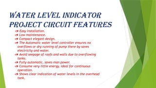
Water level indicator
projectcircuit features
Easy installation.
Low maintenance.
Compact elegant design.
The Automatic water level controller ensures no
overflows or dry running of pump there by saves
electricity and water.
Avoid seepage of roofs and walls due to overflowing
tanks.
Fully automatic, saves man power.
Consume very little energy, ideal for continuous
operation.
Shows clear indication of water levels in the overhead
tank.
Resistors:
A resistoris an electrical component
that limits or regulates the flow of
electrical current in an electronic
circuit. Resistors can also be used to
provide a specific voltage for an
active device such as a transistor .
7.
Tranisters:
A transistoris a semiconductor device used to
amplify and switch electronic signals and
electrical power . It is composed of semiconductor
material with at least three terminals for
connection to an external circuit. A voltage or
current applied to one pair of the transistor's
terminals changes the current through another pair
of terminals. Because the controlled (output) power
can be higher than the controlling (input) power,
a transistor can amplify a signal. Today, some
transistors are packaged individually, but many
more are found embedded in integrated circuits .
8.
LEDs:
Stands for"Light-Emitting Diode." An LED is
an electronic device that emits light when
an electrical current is passed through it.
Early LEDs produced only red light, but
modern LEDs can produce several different
colors, including red, green, and blue ( RGB )
light. Recent advances in LED technology
have made it possible for LEDs to produce
white light as well.
LEDs are commonly used for indicator lights
(such as power on/off lights) on electronic
devices
9.
Diodes:
A diodeis a specialized electronic
component with two electrodes called
the anode and thecathode. Most diodes are
made with semiconductor materials such as
silicon, germanium, or selenium. Some diodes
are comprised of metal electrodes in a
chamber evacuated or filled with a pure
elemental gas at low pressure. Diodes can be
used as rectifiers, signal limiters, voltage
regulators, switch es, signal modulators,
Signal mixers, signal demodulators, and
oscillators.
10.
Water level indicator
description
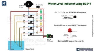
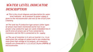
This is the circuit diagram and description for water
level indicator. A constant 5v power supply is
given to the microcontroller and rest of the circuit from
a battery.
The tank has 9 conductive type sensors (other types
of sensors have been mentioned earlier but in our
project only conductive type are used) embedded into it
and 8 wires of sensors out of 9 are connected to
transistors and the 9th is connected to 5v+ supply.
The use of transistor is it acts as inverter (i.e. in on
state gives low voltage at output and in non conducting
state gives high voltage at its output), all transistors
outputs are connected to 1,2,3,4,5,6,7,8 pins (PORTB) of
microcontroller.
11.
Seven segmentdisplay is connected to pin no. 33 to 40 (PORTA). It is connected
in common cathode fashion. The Output for the 7th level is not only shown in seven
segment display but also indicated with a discontinuous buzzer sound.
Output for the 8th level (i.e. tank full condition) is not only
shown in seven segment display but also indicated with a continuous
buzzer sound.
12.
Working of waterlevel
indicator with alarm
The operation of this project is very
simple and can be understood easily. In
our project “water level indicator” there
are 3 main conditions:
There is no water available in the source
tank.
Intermediate level i.e. either of 3rd to
7th level.
There is ample amount of water available
in the source tank.
So let us discuss on the more about these
3 conditions
13.
Condition 1:Water isnot
Available
When the tank is empty there is no conductive path
between any of the 8 indicating probes and the
common probe (which is connected to 5v+ supply) so
the transistor base emitter region will not have
sufficient biasing voltage hence it remains in cut
off region and the output across its collector will
be Vc approximately 4.2v. As in this case the
microcontroller is used in the active low region
(which means it considers 0-2 volts for HIGH and 3-
5 volts for LOW) now the output of transistor which
is 4.2v approximately will be considered as LOW by
the microcontroller and hence the default value
given by microcontroller to the seven segment
display is 1 which indicates as the tank is empty.
14.
Condition 2: intermediate
levels
Now as the water starts filling in the tank a
conductive path is established between the sensing
probes and the common probe and the corresponding
transistors get sufficient biasing at their base,
they starts conducting and now the outputs will be
Vce (i.e. 1.2v-1.8v) approximately which is given
to microcontroller. Here the microcontroller is
programmed as a priority encoder which detects the
highest priority input and displays corresponding
water level in the seven segment display. In this
project while the water level reaches the 7th level
i.e. last but one level along with display in seven
segment a discontinuous buzzer is activated which
warns user that tank is going to be full soon.
15.
Condition 3:Water full
When the tank becomes full, the top
level probe gets the conductive path
through water and the corresponding
transistor gets into conduction whose
output given to microcontroller with
this input microcontroller not only
displays the level in seven segment
display but also activates the
continuous buzzer by which user can
understand that tank is full and can
switch off the motor and save water.
16.
Applications of waterlevel
indicator :
Automatic Water level Controller can be used in
Hotels, Factories, Homes Apartments, Commercial
Complexes, Drainage, etc., It can be fixed for single
phase motor, Single Phase Submersibles, Three Phase
motors. (For 3Æ and Single Phase Submersible Starter
is necessary) and open well, Bore well and Sump. We
can control two motor and two sumps and two overhead
tanks by single unit.
Automatic water level controller will automatically
START the pump set as soon as the water level falls
below the predetermined level (usually 1/2 tank) and
shall SWITCH OFF the pump set as soon as tank is full.
Fuel level indicator in vehicles.
Liquid level indicator in the huge containers in the
companies.