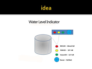
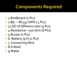
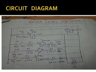
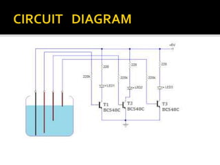
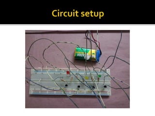
 GROUP MEMBERS
 Tanmoy Das (13-23395-1)
 ARIF ABUL AHSAN (13-23350-1)
 ALAM, S. M. NUR (13-23467-1)
 SubmittedTO======>
 Overflow Problems
 To PreventWastage Of Energy
 To PreventWastageOfWater
 Attention
 Observation
 Automatic Switch Off
 1.Bredboard (1 Pcs)
 2.Bjt ---BC547 NPN ( 4 Pcs)
 3.LED of different color (3 Pcs)
 4.Resistence—220 ohm (6 Pcs)
 5.Buzzer (1 Pcs)
 6. Battery (9V) (1 Pcs)
 7. ConnectingWire
 8.A Bowl
 9.Water
 Here’s a SIMPLE WATER LEVEL INDICATOR
CIRCUIT. It is best suited for overhead water
tanks to display the amount of water.The
circuit consisting of 3 LED’s used to indicate
minimum, medium and maximum levels. It is
possible to increase the count of indicator
LED’s and make it more convenient.The
circuit is powered by a 9V battery and it
consumes only very less current.
 The circuit consisting of 5 sensing probes which is
dipped in water to sense the level of water.The probe
A is connected as common to other three, which
should be at the bottom most part of the water tank,
also it act as a reference level.The probes B, C,D, and
E are set as minimum, middle and maximum level
respectively. Assemble the circuit on a general
purpose PCB and enclose it in a casing and mount it
with the indicator LED’s pointing out of the box. A
short length three, 18 SWG copper wires can be used
as sensing probes and for common sensor ProbeA, a
bare copper wire can be used.
 When water in the tank touches the probe A
and B both, a small current flows from A to B
through water and to the base of transistorT1
via a 220Ω resistor. As a result the transistor
conducts causing the LED1 to glow. Similarly,
when water touches sensor C, LED2 glow and
indicates that the tank is half-filled. Finally,
when the water touches sensor D, LED3
glows and indicates the tank is completely
filled
 Breadboard==250Tk =============220
 Led =====2TK(per piece)====2*3===6
 Bjt=====4TK(per piece)====4*4====16
 Battery (9V)====================40
 Resistance=====================10
 Buzzer========================20
 ConnectingWire================10
Total============322
 Water level indicator is used in applications like
storage,tanks,boilers e.t.c. to indicate level of
water inside.
 Easily indicate when water level is full in tank
with beep Sound
 It can be used to measure any liquid which are
electricity sensative
 No extra sensor need.Copper wire can be used
as sensor.
 To save energy
 To save water
 Low Cost
 Digital Fundamentals-Thomas L.Floyd(8th
Edition)
 www.electronicsforyou.com
 https://www.youtube.com/watch?v=uQj8GK
QgQxg
 www.mycircuits9.com

Water level-indiator

  • 1.
     GROUP MEMBERS Tanmoy Das (13-23395-1)  ARIF ABUL AHSAN (13-23350-1)  ALAM, S. M. NUR (13-23467-1)  SubmittedTO======>
  • 4.
     Overflow Problems To PreventWastage Of Energy  To PreventWastageOfWater  Attention  Observation  Automatic Switch Off
  • 5.
     1.Bredboard (1Pcs)  2.Bjt ---BC547 NPN ( 4 Pcs)  3.LED of different color (3 Pcs)  4.Resistence—220 ohm (6 Pcs)  5.Buzzer (1 Pcs)  6. Battery (9V) (1 Pcs)  7. ConnectingWire  8.A Bowl  9.Water
  • 8.
     Here’s aSIMPLE WATER LEVEL INDICATOR CIRCUIT. It is best suited for overhead water tanks to display the amount of water.The circuit consisting of 3 LED’s used to indicate minimum, medium and maximum levels. It is possible to increase the count of indicator LED’s and make it more convenient.The circuit is powered by a 9V battery and it consumes only very less current.
  • 9.
     The circuitconsisting of 5 sensing probes which is dipped in water to sense the level of water.The probe A is connected as common to other three, which should be at the bottom most part of the water tank, also it act as a reference level.The probes B, C,D, and E are set as minimum, middle and maximum level respectively. Assemble the circuit on a general purpose PCB and enclose it in a casing and mount it with the indicator LED’s pointing out of the box. A short length three, 18 SWG copper wires can be used as sensing probes and for common sensor ProbeA, a bare copper wire can be used.
  • 10.
     When waterin the tank touches the probe A and B both, a small current flows from A to B through water and to the base of transistorT1 via a 220Ω resistor. As a result the transistor conducts causing the LED1 to glow. Similarly, when water touches sensor C, LED2 glow and indicates that the tank is half-filled. Finally, when the water touches sensor D, LED3 glows and indicates the tank is completely filled
  • 13.
     Breadboard==250Tk =============220 Led =====2TK(per piece)====2*3===6  Bjt=====4TK(per piece)====4*4====16  Battery (9V)====================40  Resistance=====================10  Buzzer========================20  ConnectingWire================10 Total============322
  • 14.
     Water levelindicator is used in applications like storage,tanks,boilers e.t.c. to indicate level of water inside.  Easily indicate when water level is full in tank with beep Sound  It can be used to measure any liquid which are electricity sensative  No extra sensor need.Copper wire can be used as sensor.  To save energy  To save water  Low Cost
  • 15.
     Digital Fundamentals-ThomasL.Floyd(8th Edition)  www.electronicsforyou.com  https://www.youtube.com/watch?v=uQj8GK QgQxg  www.mycircuits9.com