Downloaded 230 times
![REFERENCES…
[1] RUSSELL C.HIBBELER, Mechanics of materials, 9th edition.
[2] Woong Lim & Ho-Kyung Kim, Design and development of a miniaturised tensile testing machine, Global Journal of
Engineering Education, Volume 15, Number 1, 2013
[3] Shigley, Mechanical Engineering Design, Richard G. Budynas
[4] Machine Design by V L. Maleev and Hartman
[5] https://en.wikipedia.org/wiki/Tensile_testing
[6] https://en.wikipedia.org/wiki/Linear_encoder
[7] http://www.ipaindia.com/products/double-s-load-cell/
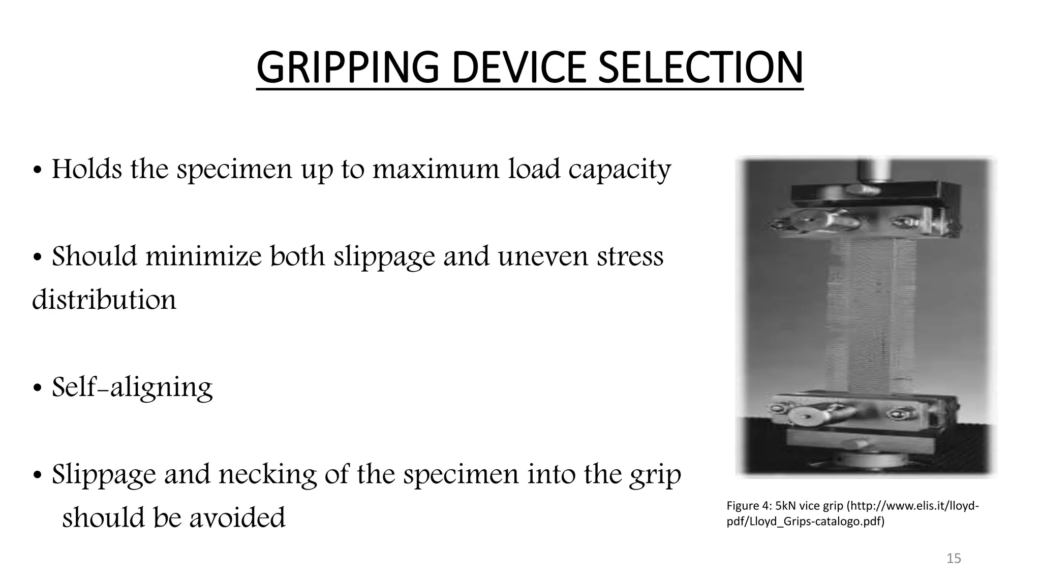
[8] http://www.elis.it/lloyd-pdf/Lloyd_Grips-catalogo.pdf
[9] http://www.motionusa.com.s3-website-us-east-1.amazonaws.com/nook/BallScrews/PowerTrac_Full_Catalog.pdf
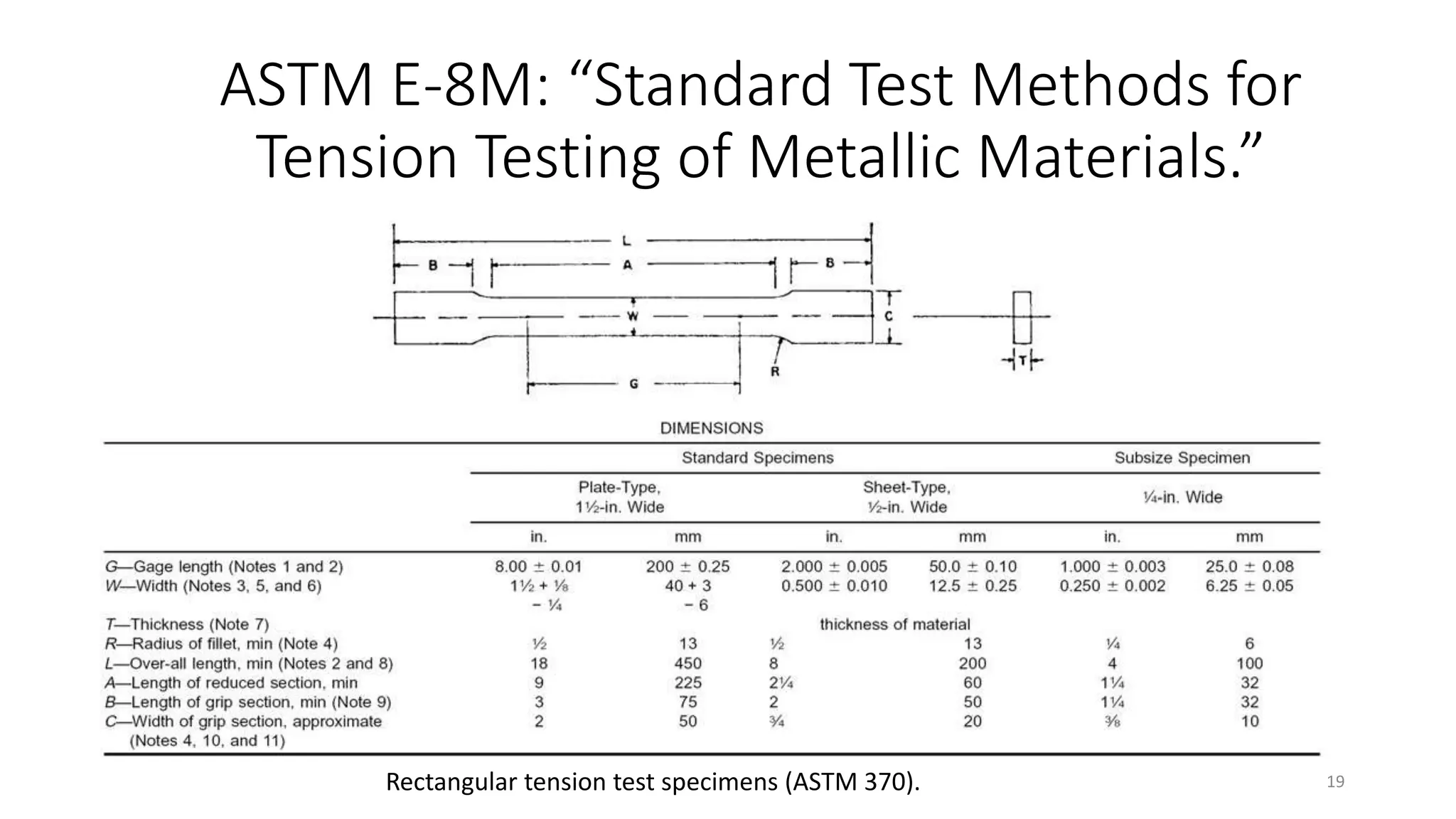
[10] http://www.festo.com/net/SupportPortal/Files/10257/Festo_10_Tips_servos_steppers.pdf
[11] https://simple.wikipedia.org/wiki/File:Nema_17_Stepper_Motor.jpg
[12] ASTM E-8M: “Standard Test Methods for Tension Testing of Metallic Materials.”
http://compass.astm.org/EDIT/html_annot.cgi?E8+15a
21](https://image.slidesharecdn.com/designanddevelopmentofhorizontaltensiletestingmachinecpp302-160513053639/75/Design-and-development-of-horizontal-tensile-testing-machine-5kN-21-2048.jpg)


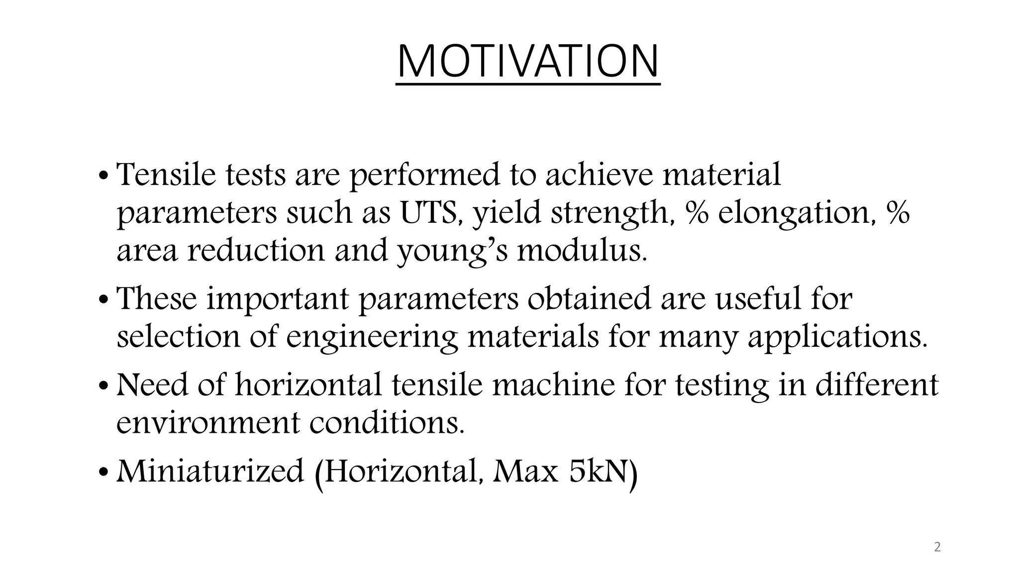
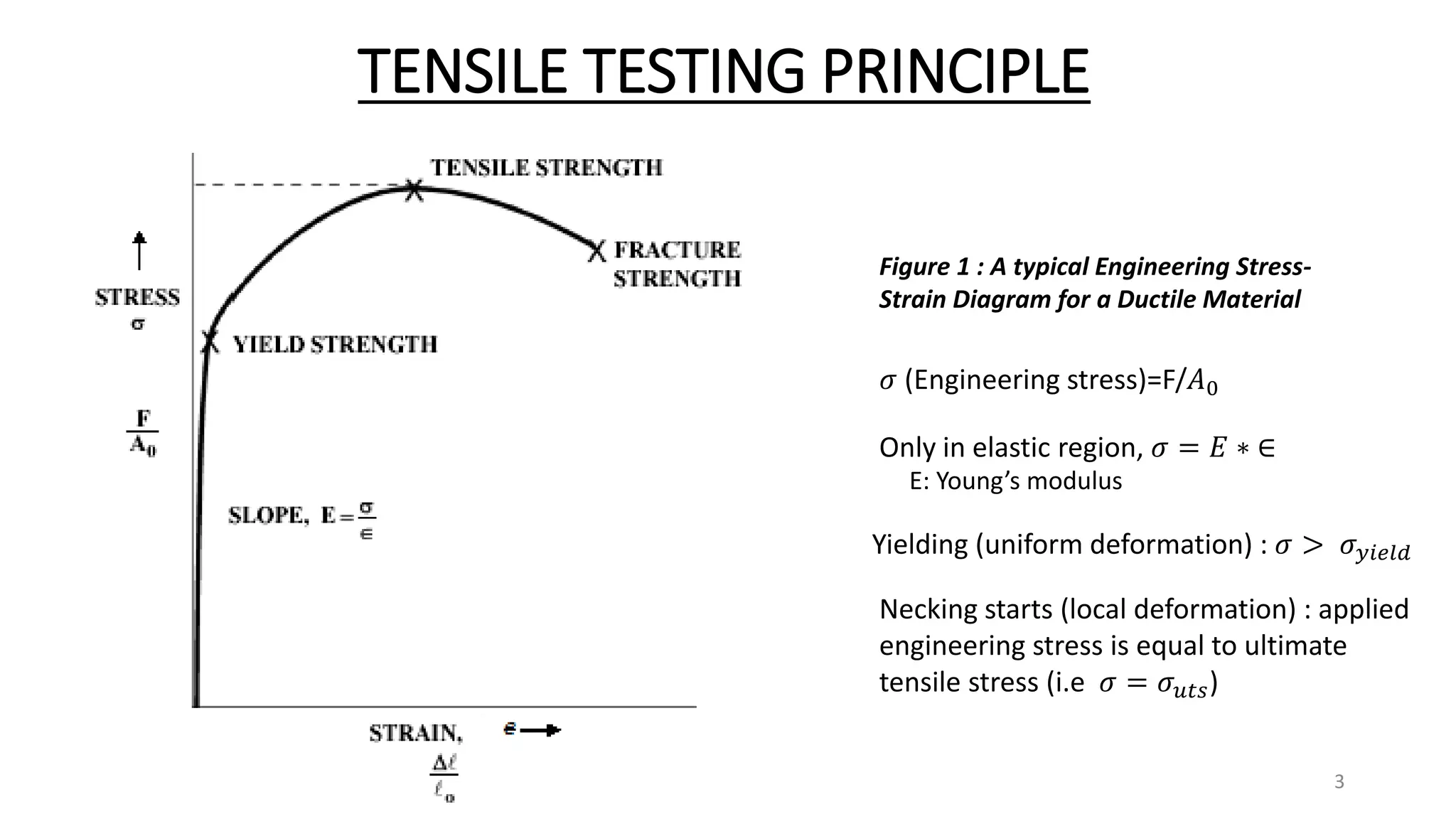
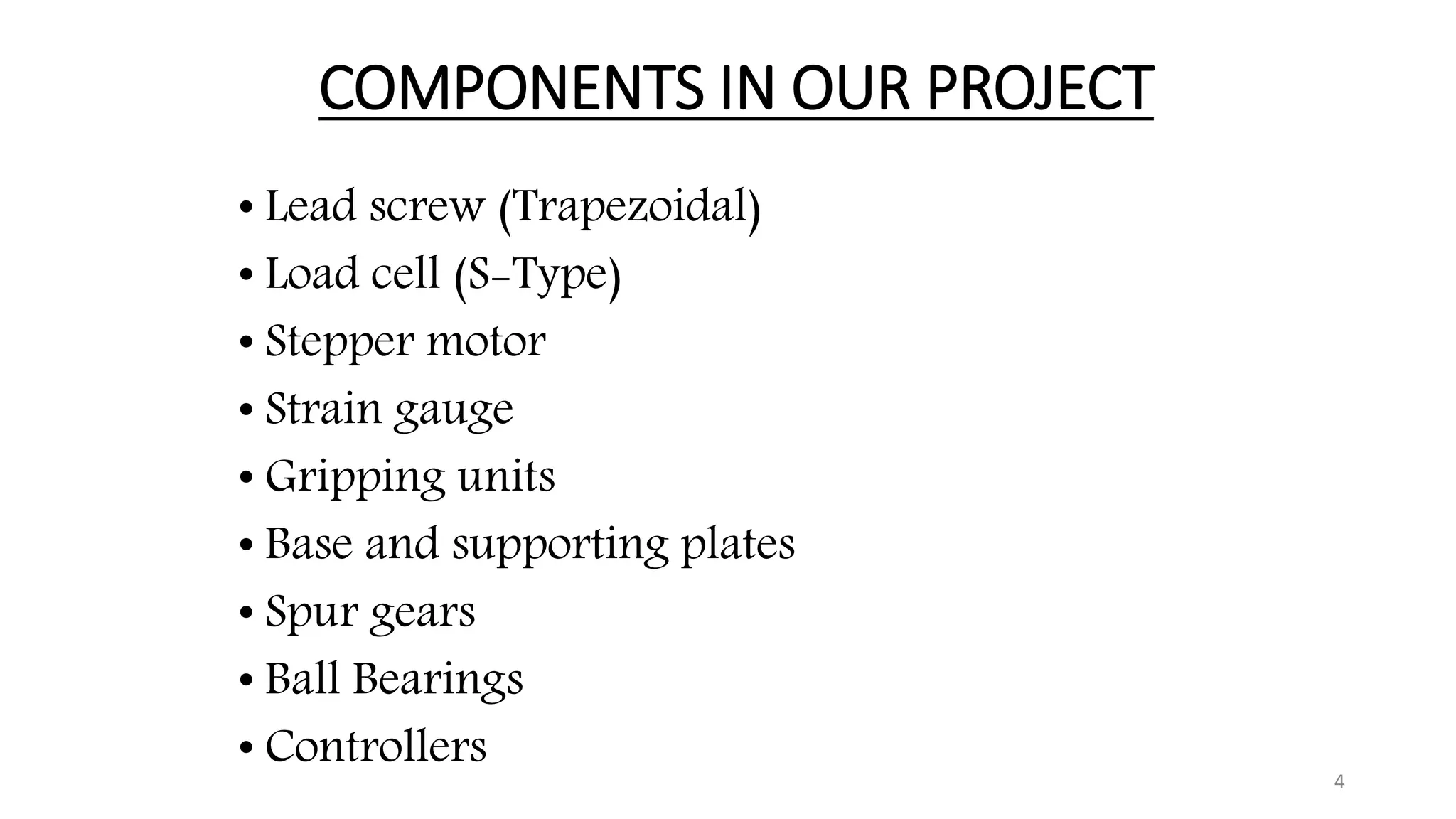
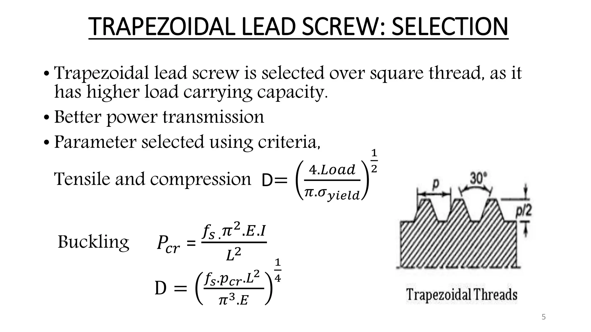
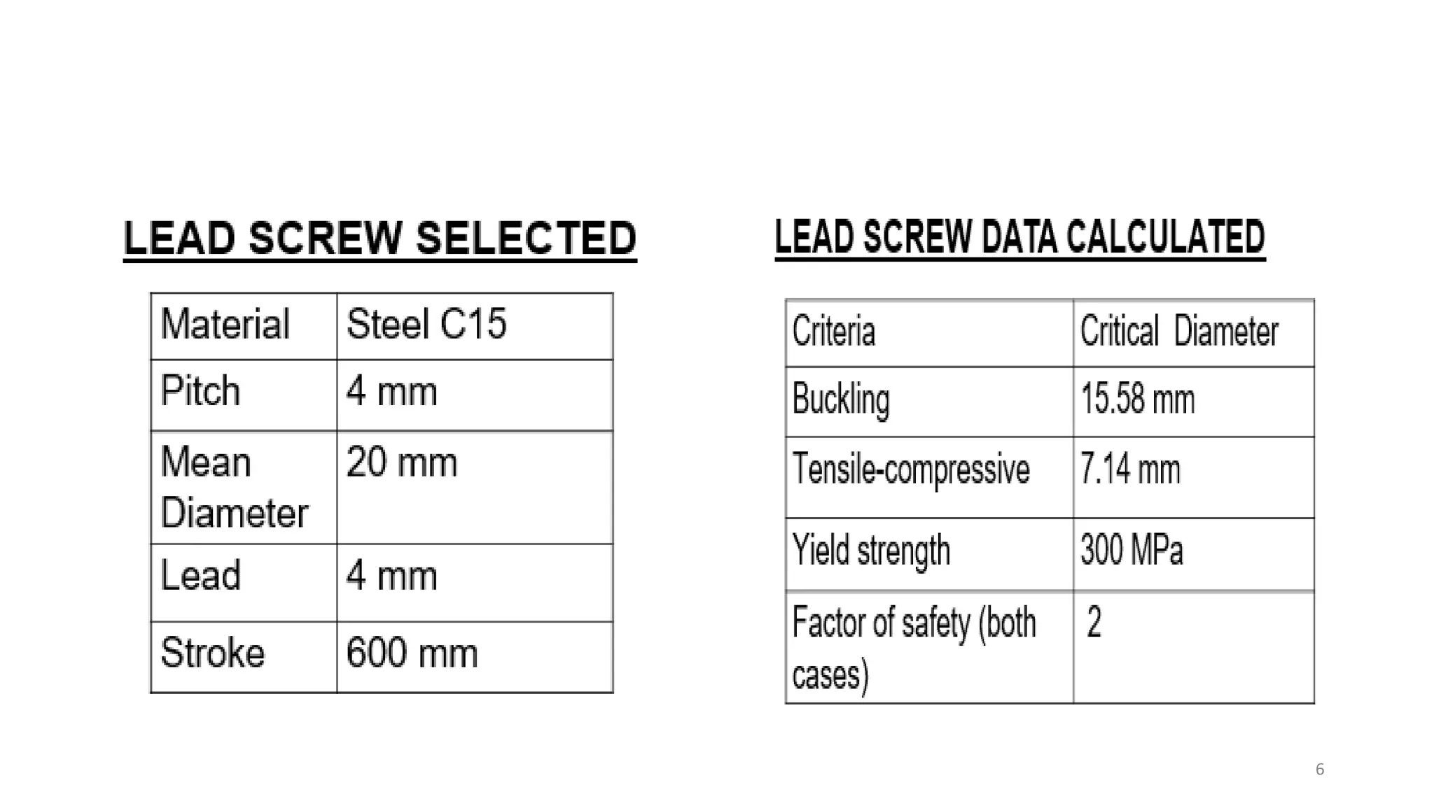
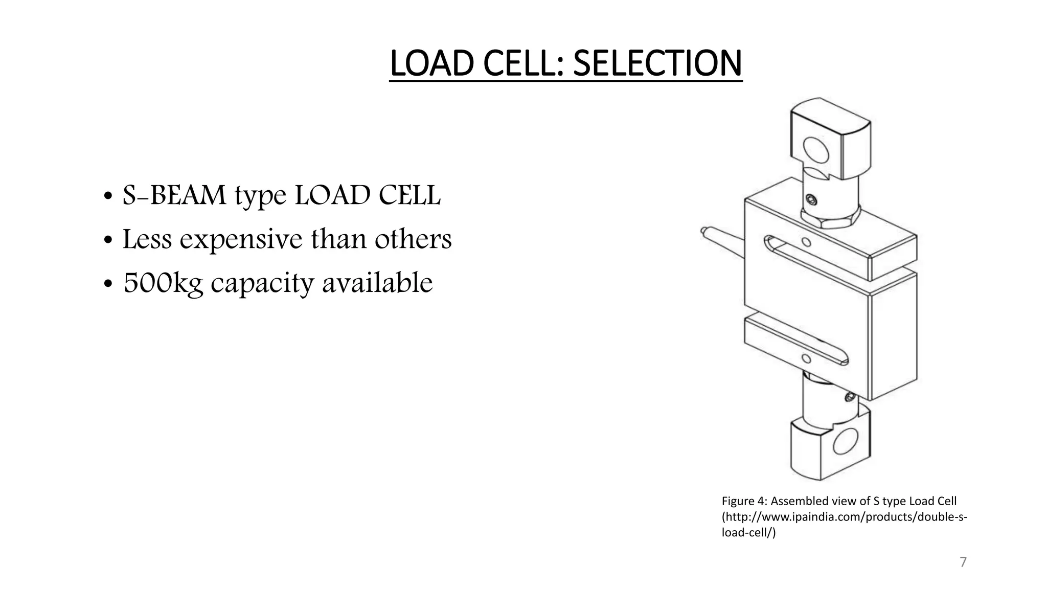
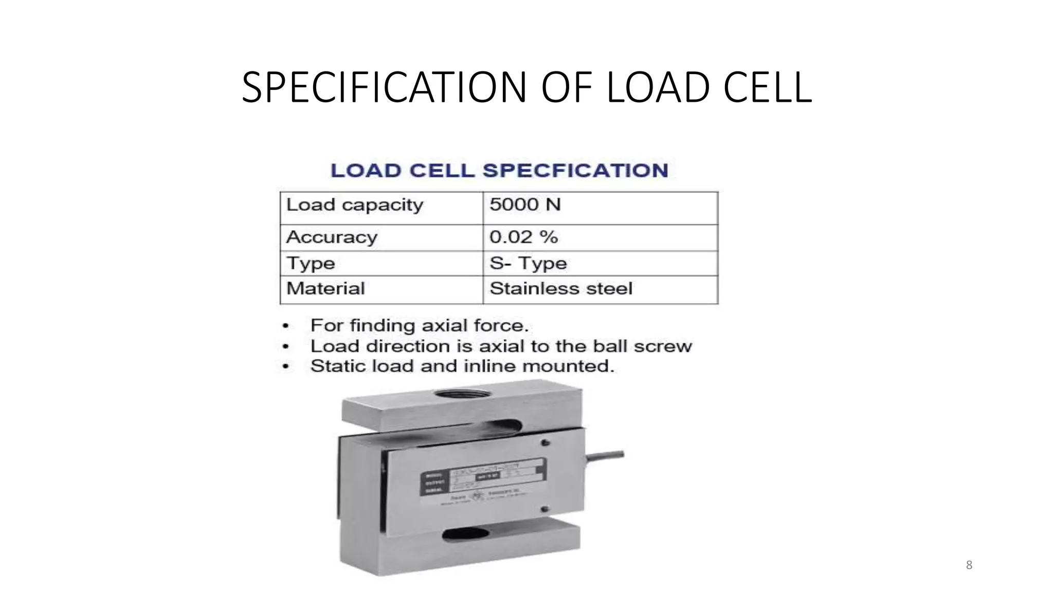
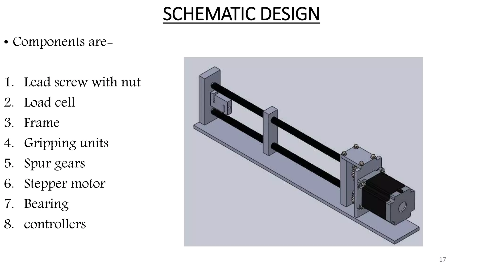
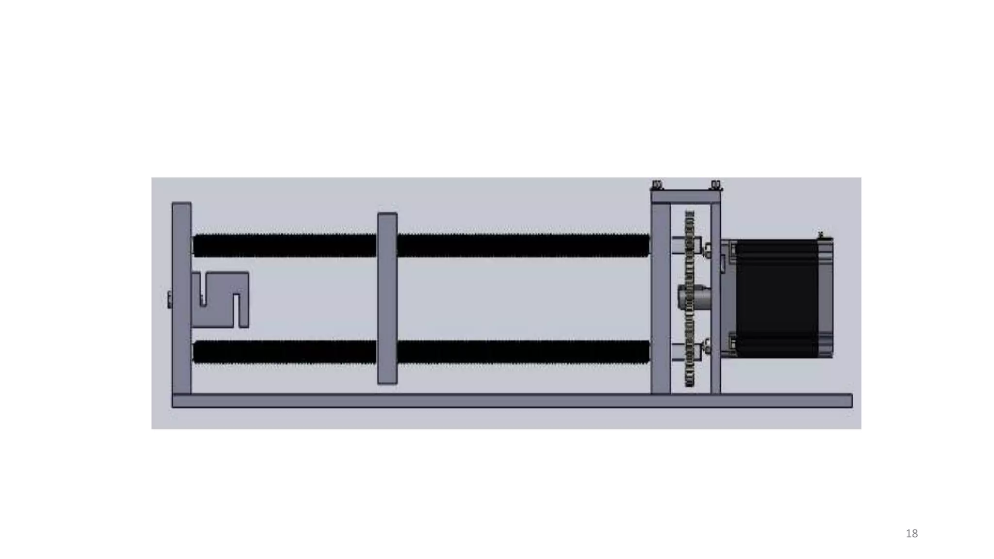
The document presents the design and development of a horizontal tensile testing machine capable of applying a maximum force of 5kN, outlining the motivation, components, and specifications for the project. Key features include a trapezoidal lead screw, an S-type load cell, and a stepper motor, all selected for their efficiency and cost-effectiveness. The machine aims to achieve essential material properties for engineering applications through standardized tension testing methods.


![Final report[1]](https://cdn.slidesharecdn.com/ss_thumbnails/finalreport1-170515065010-thumbnail.jpg?width=640&height=640&fit=bounds)


