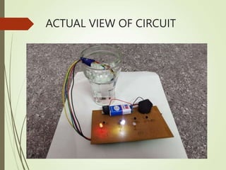
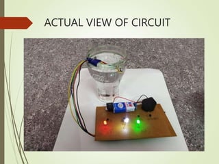
WATER LEVEL
INDICATOR USING
LEDs AND BUZZER
PRESENTED BY,
S.PAVITHRA(512518105006),
N.JAYAKODI(512518105005),
Shri sapthagiri institute of
technology,Ocheri.
ABSTRACT
 A Water Level Indicator is used to detect and indicate
the water level in an overhead tank or any other
water container.
 In this paper, we investigated the design of a water level
sensor device using LED’s , Transistor & buzzer, that
can detect the level of water in a water storage system.
INTRODUCTION
 In India, water crisis is increasing day by day and also on
another part water is wasted on many basis and one of this
includes the overflow of tank.
 So, here we are going to solve this issue in a simple manner.
 The circuit not only indicates the amount of water but also
indicates by giving an alarm when the tank is about 90%
filled.
 When the water in the tank is empty, wires in the tank are
open circuited and the resistor pulls the switch low and hence
opening the switch and led are OFF.
 As the water starts filling up, first the wire in tank connected
to low indication wire and +supply are shorted by water.
 This closes the switch low indication wire and turn the LED1
ON. As the water continues to fill the tank, LED1 & 3 lights up
gradually and when the tank is about 90% filled the buzzer
will ON.

EXISTING METHOD
 The water level indicator basically employs a simple
mechanism to detect and indicate the water level in an
overhead tank or any other water container .
 This method usually contains only LED’s or some other
methods which only visually knowing the level of water.
PROPOSED METHOD
 But here, we are knowing the level of water which is
audible.
 Because we are using an electric buzzer which
automatically gives an alarm when the overhead tank or
any other container when it is 90% filled or according to
our customs.
CIRCUIT DIAGRAM
CIRCUIT DIAGRAM EXPLANATION
 The Collector part of Transistor T1 is connected to the –ve
side of electric buzzer.
 The collector part of Transistors T2 , T3, T4 is connected to the
resistor of 1kΩ and –ve side of LED3 , LED2 & LED1 in series.
 The Emitter part of transistors T1, T2, T3 & T4 is connected to
the –ve part of 9 V DC battery.
 The +ve side of buzzer & the +ve side of LED3, LED2 & LED1
is connected to the +ve part of battery through the swtich.
 The Emitter part of transistors T1& T2 are kept in top level of
the overhead tank or container .
 The Emitter part of transistors T3 & T4 are kept in Medium &
Low level of over head tank or container respectively.
 The positive side of battery through the switch, positive side
of LED & positive side of buzzer are kept in corresponding
position through the connecting wire in the container.
HARDWARE PARTS
 LED(Light emitting diode)
 Resistance
 Buzzer
 PCB(Printed circuit board)
 Switch
 Connecting Wires
LED
 A Light emitting diode(LED) is an electronic light
source.
 LEDs are used as indicator lamps in many kinds of
electronics and increasingly for lighting.
 LEDs work by the effect of
“ELECTROLUMINESCENCE”.
 When the diode is forward biased (switching on),
electrons are able to recombine with holes and
energy id released in the form of light.
 The effect is called “ELECTROLUMINESCENCE”.
RESISTANCE
 The electrical resistance of an object is a measure of its
opposition to the passage of a steady current.
 It is discovered by GEORGE OHM in the late of 1820s.
 The SI unit of the electrical resistance is Ohm(Ω ).
 The resistance of a resistive object determines the
amount of current through the object for a given
potential difference V across the object, in accordance
with the Ohm’s law;
 I=V/R
 Where R is the resistance of the object, measure in
Ohms, equivalent to J.(s/c^2).
TRANSISTOR(BC547)
 A transistor is a semiconductor device commonly used
to amplify or switch electronic signals.
 A transistor is made of a solid piece of semiconductor
material, with atleast three terminals for connection to
an external circuit.
 This is a NPN transistor.
ELECTRIC BUZZER
 A piezoelectric buzzer consists of an electric ceramic
plate which has electrodes of both sides and a metal
plate.
 An electric ceramic plate is attached to a metal plate
with adhesives.
 Applying D.C voltage between electrodes of a
piezoelectric ceramic plate causes mechanical
distortion due to piezoelectric effect.
PRINTED CIRCUIT BOARD
 A printed circuit board, or PCB, is used to
mechanically support and electrically connect
electronic components using conductive
pathways, tracks or traces, etched from copper
sheets laminated on to a non-conductive
substrate.
WORKING PRINCIPLE
 One electrode wire is with 9V battery is placed
at the bottom of tank.
 Next wires are placed step by step above the
bottom probe.
 When the water comes in contact with the
electrode tip, a conductive path is established
between the sense electrode and the tank
wall/reference electrode, which in turn makes the
transistors conduct to glow LED and indicate the
level of water.
ACTUAL VIEW OF CIRCUIT
SOLDERING
 Soldering is a process in which two or more metal items
are joined together by melting and flowing a filler metal
into a joint, the filler metal having a relatively low
melting point.
 After the metal cools, the resulting joints are not as
strong as the base metal, but have adequate strength,
electrical conductivity, and water-tightness for many
uses.
ADVANTAGES
 It is more economic.
 Cost is comparatively low.
 No more wastage of water.
 Easy installation and monitoring.
DRAWBACKS
 Electronics are built separately.
 May not work with agitated liquids.
 The rust, foul and deteriorate.
FUTURE SCOPE & ENANCHEMENT
 Now there is no need to look the water
levrl.
 It shows the water level in your place like it
quarter tank, or half tank of full tank.
 Alarm starts ringing as soon as the tank is
90% filled.
 It is suitable for every tank.
REFERENCE
 Social media
Youtube
Channel Name : Top 10 tamil
THANK YOU

518821613-Water-Level-Indicator-1bsjsjsj.ppt

  • 1.
    WATER LEVEL INDICATOR USING LEDsAND BUZZER PRESENTED BY, S.PAVITHRA(512518105006), N.JAYAKODI(512518105005), Shri sapthagiri institute of technology,Ocheri.
  • 2.
    ABSTRACT  A WaterLevel Indicator is used to detect and indicate the water level in an overhead tank or any other water container.  In this paper, we investigated the design of a water level sensor device using LED’s , Transistor & buzzer, that can detect the level of water in a water storage system.
  • 3.
    INTRODUCTION  In India,water crisis is increasing day by day and also on another part water is wasted on many basis and one of this includes the overflow of tank.  So, here we are going to solve this issue in a simple manner.  The circuit not only indicates the amount of water but also indicates by giving an alarm when the tank is about 90% filled.  When the water in the tank is empty, wires in the tank are open circuited and the resistor pulls the switch low and hence opening the switch and led are OFF.  As the water starts filling up, first the wire in tank connected to low indication wire and +supply are shorted by water.  This closes the switch low indication wire and turn the LED1 ON. As the water continues to fill the tank, LED1 & 3 lights up gradually and when the tank is about 90% filled the buzzer will ON. 
  • 4.
    EXISTING METHOD  Thewater level indicator basically employs a simple mechanism to detect and indicate the water level in an overhead tank or any other water container .  This method usually contains only LED’s or some other methods which only visually knowing the level of water.
  • 5.
    PROPOSED METHOD  Buthere, we are knowing the level of water which is audible.  Because we are using an electric buzzer which automatically gives an alarm when the overhead tank or any other container when it is 90% filled or according to our customs.
  • 6.
  • 7.
    CIRCUIT DIAGRAM EXPLANATION The Collector part of Transistor T1 is connected to the –ve side of electric buzzer.  The collector part of Transistors T2 , T3, T4 is connected to the resistor of 1kΩ and –ve side of LED3 , LED2 & LED1 in series.  The Emitter part of transistors T1, T2, T3 & T4 is connected to the –ve part of 9 V DC battery.  The +ve side of buzzer & the +ve side of LED3, LED2 & LED1 is connected to the +ve part of battery through the swtich.  The Emitter part of transistors T1& T2 are kept in top level of the overhead tank or container .  The Emitter part of transistors T3 & T4 are kept in Medium & Low level of over head tank or container respectively.  The positive side of battery through the switch, positive side of LED & positive side of buzzer are kept in corresponding position through the connecting wire in the container.
  • 8.
    HARDWARE PARTS  LED(Lightemitting diode)  Resistance  Buzzer  PCB(Printed circuit board)  Switch  Connecting Wires
  • 9.
    LED  A Lightemitting diode(LED) is an electronic light source.  LEDs are used as indicator lamps in many kinds of electronics and increasingly for lighting.  LEDs work by the effect of “ELECTROLUMINESCENCE”.  When the diode is forward biased (switching on), electrons are able to recombine with holes and energy id released in the form of light.  The effect is called “ELECTROLUMINESCENCE”.
  • 10.
    RESISTANCE  The electricalresistance of an object is a measure of its opposition to the passage of a steady current.  It is discovered by GEORGE OHM in the late of 1820s.  The SI unit of the electrical resistance is Ohm(Ω ).  The resistance of a resistive object determines the amount of current through the object for a given potential difference V across the object, in accordance with the Ohm’s law;  I=V/R  Where R is the resistance of the object, measure in Ohms, equivalent to J.(s/c^2).
  • 11.
    TRANSISTOR(BC547)  A transistoris a semiconductor device commonly used to amplify or switch electronic signals.  A transistor is made of a solid piece of semiconductor material, with atleast three terminals for connection to an external circuit.  This is a NPN transistor.
  • 12.
    ELECTRIC BUZZER  Apiezoelectric buzzer consists of an electric ceramic plate which has electrodes of both sides and a metal plate.  An electric ceramic plate is attached to a metal plate with adhesives.  Applying D.C voltage between electrodes of a piezoelectric ceramic plate causes mechanical distortion due to piezoelectric effect.
  • 13.
    PRINTED CIRCUIT BOARD A printed circuit board, or PCB, is used to mechanically support and electrically connect electronic components using conductive pathways, tracks or traces, etched from copper sheets laminated on to a non-conductive substrate.
  • 14.
    WORKING PRINCIPLE  Oneelectrode wire is with 9V battery is placed at the bottom of tank.  Next wires are placed step by step above the bottom probe.  When the water comes in contact with the electrode tip, a conductive path is established between the sense electrode and the tank wall/reference electrode, which in turn makes the transistors conduct to glow LED and indicate the level of water.
  • 15.
  • 16.
  • 17.
  • 18.
  • 19.
    SOLDERING  Soldering isa process in which two or more metal items are joined together by melting and flowing a filler metal into a joint, the filler metal having a relatively low melting point.  After the metal cools, the resulting joints are not as strong as the base metal, but have adequate strength, electrical conductivity, and water-tightness for many uses.
  • 20.
    ADVANTAGES  It ismore economic.  Cost is comparatively low.  No more wastage of water.  Easy installation and monitoring.
  • 21.
    DRAWBACKS  Electronics arebuilt separately.  May not work with agitated liquids.  The rust, foul and deteriorate.
  • 22.
    FUTURE SCOPE &ENANCHEMENT  Now there is no need to look the water levrl.  It shows the water level in your place like it quarter tank, or half tank of full tank.  Alarm starts ringing as soon as the tank is 90% filled.  It is suitable for every tank.
  • 23.
  • 24.