This document discusses different types of flowmeters used to measure volumetric and mass flow rates. It begins by introducing key terms and concepts, such as the relationship between volumetric and mass flow rates given fluid density. There are two broad categories of flowmeters: end-line flowmeters which measure flow at the outlet, and in-line flowmeters which are placed within a pipe.
Common in-line flowmeters include obstruction flowmeters like orifice plates, flow nozzles, and Venturi meters which create a pressure drop to measure flow. Positive displacement meters fill and empty a known volume over time. Turbine and rotary meters rely on spinning components, while other technologies use magnetic, optical, or acoustic effects
![Volume and Mass Flow Rate Measurement, Page 1
Volume and Mass Flow Rate Measurement
Author: John M. Cimbala, Penn State University
Latest revision: 09 December 2009
Introduction and notation
• In many engineering applications, either mass flow rate or volume flow rate must be measured.
• Notation used in this learning module:
o Velocity V and volume V are distinguished either by adding a bar through the V to indicate volume ( V )
or by using a different font (V).
o Mass flow rate and volume flow rate are indicated by adding an overdot on m or V respectively.m V
o Some authors use Q for volume flow rate, but this gets confused with heat transfer – I prefer .V
• If the density ρ of the fluid is known, mass flow rate and volume flow rate are related by m ρ= V .
• In all the examples used in this learning module, we consider only incompressible flow. Special care must be
taken when the flow is compressible, such as the flow of air or natural gas through a pipeline.
• Most of the instruments discussed here measure volume flow rate; other instruments measure mass flow rate.
Mass flow rate measurements are more common in gases [gas density varies more than does liquid density].
• Instruments that measure volume flow rate are called flowmeters.
• There are two broad categories of flowmeter:
o An end-line flowmeter, also called a discharge flowmeter, is used at the
outlet or discharge of the flow – at the end of the line.
To measure volume flow rate, we measure how much time Δt it takes
to fill up a container of known volume, and calculate / t= ΔV V .
A simple example of an end-line flowmeter is measurement of the
volume flow rate through a garden hose using a bucket and
stopwatch, as sketched to the right.
There are some variations of the bucket and stop-watch approach –
for example, we may weigh the fluid instead, and calculate the mass
flow rate instead of the volume flow rate.
End-line flow measurement is extremely accurate, and is often used to calibrate in-line flowmeters.
• An in-line flowmeter is a device that is placed in line with the pipe or duct rather than at the outlet.
o An in-line flowmeter is necessary when the outlet or discharge is not available or splits into many
separate outlets. For example, the water company must measure the volume of water used in your home
or apartment. Obviously, an end-line technique would not work here.
o There are five main categories of in-line flowmeters:
Obstruction flowmeters – measure the pressure drop across an obstruction placed in the flow.
Positive displacement flowmeters – fill up a known volume and then pass it on down the line.
Turbine flowmeters or paddlewheel flowmeters – spin a shaft and measure its rpm.
Rotameters – raise an object due to aerodynamic drag, and measure its height.
Miscellaneous flowmeters – use magnetic, optical, sonic, ultrasonic, vortex shedding, or various
other means to measure volume flow rate.
o We discuss each of these types of end-line flowmeters individually in the notes below.
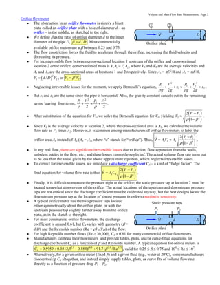
Obstruction flowmeters
• The operating principle of an obstruction flowmeter is as follows:
o A pressure drop is created in the pipe or duct by adding some kind of obstruction, as sketched below.
Obstruction D VV
o The pressure drop associated with the obstruction is measured.
o The volume flow rate is calibrated as a function of measured pressure drop.
• All obstruction flowmeters cause a pressure drop (irreversible head loss) in the piping system – this pressure
drop is called a minor loss.
• There are three main types of obstruction flowmeter – orifice, flow nozzle, and Venturi. All work on the
same principle, but have different performance characteristics.
• We develop the equations for the orifice flowmeter – the equations for the flow nozzle and Venturi
flowmeters are the same, but with a different discharge coefficient.](https://image.slidesharecdn.com/volumeflowratemeasurement-151129053213-lva1-app6891/85/Volume-flow-rate_measurement-1-320.jpg)

![Volume and Mass Flow Rate Measurement, Page 4
Venturi flowmeter
• A Venturi flowmeter (usually called simply a Venturi meter) works under the same operating principle as
the other two obstruction flowmeters – pressure drop through
an obstruction.
dV D
Diffuser
P2P1
Static pressure taps
• The obstruction in a Venturi meter is not only rounded on the
upstream side, as in a flow nozzle, but also has a gradual
expansion (a diffuser) on the downstream side from throat
diameter d to pipe inner diameter D, as sketched to the right.
• The flow is efficiently guided through the opening, just as in
the flow nozzle flowmeter, and thus the discharge coefficient
is similar to but slightly larger than that of a flow nozzle.
• To maximize sensitivity, the downstream (low pressure) pressure tap is located in the smallest diameter
portion of the Venturi meter – the throat, where the pressure is a minimum and the velocity is a maximum.
• For high Reynolds number flows (Re > 30,000), 0.98dC = for a well designed Venturi flowmeter; Reynolds
number correction is typically not necessary since Cd is so large and nearly constant.
• The most significant improvement in the Venturi meter compared to the flow nozzle is in the minor loss
(irreversible loss). Because of the gradual diffuser in the Venturi meter, the highly turbulent mixing zone that
is present downstream of the nozzle is eliminated, and the pressure recovery is much greater, thereby
reducing the irreversible losses significantly.
• Venturi flowmeters are more expensive than orifice flow meters or flow nozzle flowmeters because of their
more complicated geometry, but have maximum sensitivity due to the larger value of the discharge
coefficient, and contribute the smallest minor loss of the three to the overall pipe or duct system.
• In applications where large pressure drops cannot be tolerated, the Venturi meter is a wise choice.
Laminar flow element
• A laminar flow element (also called a laminar
flowmeter or flow element) works under the same
operating principle as all obstruction flowmeters –
pressure drop through an obstruction.
• However, the distinguishing factor here is that the
flow through the pipe or duct is distributed through
hundreds or thousands of small diameter tubes, as
illustrated in the diagram to the right. [Note that the tubes need not be round in cross section.]
d
V D
P2P1
Axial view
Static pressure taps
Side view
V
L
• The Reynolds number is pipeRe
VD
=
ρ
μ
for the pipe flow itself, where ρ is the fluid density, V is the average
velocity through the pipe or duct, D is the pipe’s inner diameter, and μ is the viscosity of the fluid.
• However, the Reynolds number through each individual tube is tubeRe
c
Vd A
A
=
ρ
μ
, where d is the inner
diameter of the tube, A = πD2
/4 is the cross-sectional area of the pipe, and Ac is the open cross-sectional area
as seen looking down the pipe (the axial view in the above sketch).
• Since the tubes have small but finite wall thickness, Ac is smaller than A (sometimes by a factor approaching
2 for very small tubes). The average velocity through an individual tube is VA/Ac, which is larger than V.
• As is known from your study of fluid mechanics, the flow through one of the small tubes remains laminar
provided that Retube is less than about 2000. Thus, if sized properly, the flow through each individual small
tube is laminar, even though the flow through the pipe itself may be turbulent.
• Since tube length is large compared to tube diameter (L/d >> 1), entrance losses are small compared to the
so-called major loss through the tube, and the pressure drop ΔP = P1 – P2 for laminar flow through the tube
is nearly linearly proportional to volume flow rate.
• The main advantage of the laminar flow element is that volume flow rate is proportional to ΔP, unlike other
obstruction flowmeters (orifice, flow nozzle, and Venturi), in which volume flow rate is proportional to the
square root of ΔP. This allows the laminar flow element to operate over a wider range of volume flow rates
without compromising the accuracy – after calibration, accuracies can be as good as ±0.25%.
• Some disadvantages of the laminar flow element: The blockage (a so-called minor loss) is large compared to
that of other obstruction flowmeters. Large volume flow rates require tiny diameter tubes to keep the flow
laminar. If the flow is dirty, the tubes can become clogged and may need occasional cleaning.](https://image.slidesharecdn.com/volumeflowratemeasurement-151129053213-lva1-app6891/85/Volume-flow-rate_measurement-4-320.jpg)


