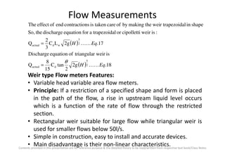
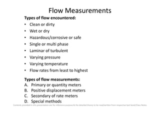
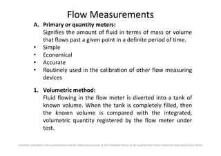
Flow Measurements
Types of flow encountered:
• Clean or dirty
• Wet or dry
• Hazardous/corrosive or safe
• Single or multi phase
• Laminar of turbulent
• Varying pressure
Contents provided in this presentation are for reference purpose & the detailed theory to be read/written from respective text book/Class Notes
• Varying pressure
• Varying temperature
• Flow rates from least to highest
Types of flow measurements:
A. Primary or quantity meters
B. Positive displacement meters
C. Secondary of rate meters
D. Special methods
Flow Measurements
A. Primary or quantity meters:
Signifies the amount of fluid in terms of mass or volume
that flows past a given point in a definite period of time.
• Simple
• Economical
• Accurate
• Routinely used in the calibration of other flow measuring
devices
Contents provided in this presentation are for reference purpose & the detailed theory to be read/written from respective text book/Class Notes
devices
1. Volumetric method:
Fluid flowing in the flow meter is diverted into a tank of
known volume. When the tank is completely filled, then
the known volume is compared with the integrated,
volumetric quantity registered by the flow meter under
test.
Flow Measurements
2. Gravimetric method:
Fluid flowing in the flow meter is diverted into a vessel
which can be weighted either continuously or in the
vessel after a pre-determined time. The weight of the
liquid collected is compared with the gravimetric quantity
registered by the flow meter under test.
B. Positive Displacement Meters:
Liquid flows through a meter and moves the measuring
Contents provided in this presentation are for reference purpose & the detailed theory to be read/written from respective text book/Class Notes
Liquid flows through a meter and moves the measuring
element that seals the measuring chamber into a series of
measuring compartments each holding a definite volume.
Each element is successively filled from the flow at the
inlet and emptied at the outlet of the meter. In other
words these meters chop the flow into number of pieces
of known size and then count the number of pieces.
Flow Measurements
Features:
• Widely used in low flow rate metering applications where
high accuracy & repeatability are required.
• Easy to install
• Moderate cost
• Due to moving parts involved, wear of the components may
alter the accuracy.
• Suitable to clean fluids only.
Contents provided in this presentation are for reference purpose & the detailed theory to be read/written from respective text book/Class Notes
• Suitable to clean fluids only.
• These devices are flow totalizes and generally and do not
give the instantaneous rate of flow.
• Cause pressure loss in the fluid system whose flow is being
metered.
Flow Measurements
1. Nutating Disc Meters:
Contents provided in this presentation are for reference purpose & the detailed theory to be read/written from respective text book/Class Notes
Flow Measurements
Working:
• Liquid enters the left side of the meter, alternately above &
below the disc, forcing it to rock in a circular path while
rotating about its own axis.
• A small spindle attached to the sphere traces a circular path
and is used to drive the counter, which can be calibrated in
terms of liquid discharge.
Features:
Contents provided in this presentation are for reference purpose & the detailed theory to be read/written from respective text book/Class Notes
Features:
• Simple & rugged construction
• Low pressure drop
• Low cost
• High accuracy of the order of ±1%.
• Widely used as a domestic water meter
Flow Measurements
2. Sliding Vane Type Meters:
Contents provided in this presentation are for reference purpose & the detailed theory to be read/written from respective text book/Class Notes
Flow Measurements
Working:
• Liquid entering at inlet revolves the rotor and the vanes
around cam causing the vanes to move radially.
• Vane nearest to the inlet port begins to move outwards &
becomes fully extended at point A. While vane ahead at
point B is already fully extended, so a measuring chamber
of known volume is formed.
• A continuous series of chambers at the rate of four per
Contents provided in this presentation are for reference purpose & the detailed theory to be read/written from respective text book/Class Notes
• A continuous series of chambers at the rate of four per
revolution are formed.
Features:
• Low pressure drop
• High accuracy of the order of ±0.2% of measured values.
• Can be used as a positive displacement pump which can
cause the flow and measure it simultaneously.
Flow Measurements
3. Lobed Impeller Meters:
Contents provided in this presentation are for reference purpose & the detailed theory to be read/written from respective text book/Class Notes
Flow Measurements
Working:
• The incoming fluid is trapped between the two rotors and is
conveyed to outlet as a result of the rotor rotations.
• For every rotation of each rotor, the swept volume
corresponding to twice the area A is passed through meter.
• Number of revolutions of the rotor gives and indication of
volumetric flow.
• Rotation of lobed impellers can be monitored by magnetic
Contents provided in this presentation are for reference purpose & the detailed theory to be read/written from respective text book/Class Notes
• Rotation of lobed impellers can be monitored by magnetic
or photo-electric pick up.
Features:
• Available for pressures up to 60 atm and flow range 10 to
10,000 m3/hr.
• High accuracy of the order of ±1% of rated capacity.
• Low pressure drop of the order of 50 mm of Hg.
• Relatively expensive.
• Applicable to clean fluids like gas metering.
Flow Measurements
C. Secondary or Rate Meters:
• Also termed as inferential type of flow measuring devices.
• They do not measure flow directly but instead measure
another physical quantity which is related to flow.
• Two categories:
Flow rate meters
Velocity meters or Anemometers
Contents provided in this presentation are for reference purpose & the detailed theory to be read/written from respective text book/Class Notes
Flow Measurements
1. Variable Head Meters:
Features:
• Generally termed as obstruction type flow meters.
• The main forms of obstructions are: Venturi, orifice plate
and nozzle.
• The position of minimum pressure is located slightly
downstream from the restriction at a point where the
Contents provided in this presentation are for reference purpose & the detailed theory to be read/written from respective text book/Class Notes
downstream from the restriction at a point where the
stream is narrowest and is called vena- contracta.
• Beyond this point the pressure the pressure again rises but
does not return to upstream value and thus there is
permanent pressure loss.
• No moving parts & so require no maintenance practically.
• Major disadvantage is square root relationship between
flow and head.
• Not suitable for flow below 20% of rated meter capacity.
Flow Measurements
a) Venturi Meter:
Contents provided in this presentation are for reference purpose & the detailed theory to be read/written from respective text book/Class Notes
Flow Measurements
b) Orifice Meter:
Contents provided in this presentation are for reference purpose & the detailed theory to be read/written from respective text book/Class Notes
Flow Measurements
c) Nozzle Meter:
Contents provided in this presentation are for reference purpose & the detailed theory to be read/written from respective text book/Class Notes
Flow Measurements
Eqhg
AA
AA
solvingBy
Eqh
EqslliFromBernou
Eq
General
4.2Q:3&2Eq.1,
3.
g
p-p
:manometeratprdiffThe
2.
2
V
p
2
V
p:Eq.'
1.VAVAQ:dischargeofRate
:flowofrateforexpression
2
2
2
1
21
ideal
21
2
2
2
2
1
1
2211
∆
−
=
∆=
+=+
==
KK
KK
KK
KK
ρ
ρρ
Contents provided in this presentation are for reference purpose & the detailed theory to be read/written from respective text book/Class Notes
g
AA
AA
EqhK
Eqhg
AA
AA
tCoefficien
practiceInactual
2KWhere
6.CQOr
5.2CQ
dischargeof
Q
Q
C
:soflow,actualthanmorealwaysisQ
2
2
2
1
21
dactual
2
2
2
1
21
dactual
ideal
actual
d
ideal
21
−
=
∆=
∆
−
=∴
==
KK
KK
Flow Measurements
Coefficient of discharge depends on:
• Type of flow
• Obstruction type configuration
• Reynolds number
Venturimeter Features:
• Best accuracy
• Least head loss as compared to orifice & nozzle meters
Contents provided in this presentation are for reference purpose & the detailed theory to be read/written from respective text book/Class Notes
• Least head loss as compared to orifice & nozzle meters
• Due to low value of losses coefficient of discharge is high
• Can be used with dirty fluids also
• Relatively expensive
• Occupies substantial space
Flow Measurements
Nozzle Flow meter Features:
• Offers all the advantages of venturimeter but to a lesser
extent
• Occupies less space
• Nozzle is difficult to install and the installation is limited to
small to moderate pipe sizes
Orifice Flow meter Features:
Contents provided in this presentation are for reference purpose & the detailed theory to be read/written from respective text book/Class Notes
Orifice Flow meter Features:
• Simple geometry, so cost is low
• Easy to install
• Takes almost no space
• Susceptible to inaccuracies due to erosion, corrosion,
clogging etc.
• Suffers from a head loss of the order of 30-40%
Flow Measurements2. Variable Area Meters: Features:
• In variable area meters the
area of restriction can be
altered to maintain the steady
pressure difference.
• Common variable area meter
is rotameter.
• The float will rise to a point in
the tube where the drag force
Contents provided in this presentation are for reference purpose & the detailed theory to be read/written from respective text book/Class Notes
the tube where the drag force
(Up) & Buoyant force (Up) is
balance by the weight of the
float.
• The position of the float in
the tube is taken as an
indication of flow rate.
• It is also called as variable
area flow meter.
Flow Measurements
)p-p()(
floatoffacesupward&downwardat thepressuresthearep&p
floattheofvolumetheisV
lyrespectivefluidflowingandfloattheofdensitiestheare&Where
7.)(
A
V
)p-p(
gVgV)p-(pA
FFF
:isfloattheofforequationbalanceforceThe
ud
f
fff
fff
f
f
ud
fffffudf
weightbuoyancydrag
AAA
Eqg
Or
KK
−
−=∴
=+
=+
ρρ
ρρ
ρρ
Contents provided in this presentation are for reference purpose & the detailed theory to be read/written from respective text book/Class Notes
10.)(Q:Then,1
)(
If
9.
)(
A
V
2
)(
1
)(
CQ:8&Eq.7From
float&tubeebetween thareaannularmintheis)(
levelfloatattubetheofareatheisA
8.
)p-p(
2
)(
)(
CQ:earlierEq.6From
actual
ff
fff
f
f
2
2dactual
t
ff
ud
22dactual
EqAAK
A
AA
Eqg
A
AA
AA
AA
Where
Eq
g
g
AAA
AAA
ft
t
ft
t
ft
ft
ft
ftt
ftt
KK
KK
KK
−=<<
−
−
−
−
−
=
−
−−
−
=
ρ
ρρ
ρ
Flow Measurements
inletatdiaisandinletrespect toithposition wfloattheisyWhere
11.tan
24
)tan(
4
thensmall),veryis(WhichistaperofangletheIf
constantrotametertheisKWhere
2
2
D
EqyDDAOr
yDA
i
iit
it
KK+=
+=
θ
ππ
θ
π
θ
Contents provided in this presentation are for reference purpose & the detailed theory to be read/written from respective text book/Class Notes
scale.linearaonfloattheofreadingdirectagivesrotameterThus
float&rotametertheofshapeon thedependingconstantsareK&Where
13.Q
12.)
4
(tan
2
Q
)tan
24
(Q
11&Eq.10From
21
21actual
2
actual
2
actual
K
EqKyK
EqADKyDK
AyDDK
fii
fii
KK
KK
+=
−+=
−+=
π
θ
π
θ
ππ
Flow Measurements
Rotameter Features:
• Rotameter tube is made of high strength borosilicate glass
to allow direct observation of the float position.
• Main advantage is that they give direct visual indication on
linear scale.
• Can be used for wide ranges (from 0.1 ml/min to several
hundred lpm)
Contents provided in this presentation are for reference purpose & the detailed theory to be read/written from respective text book/Class Notes
hundred lpm)
• Accuracy is generally ±1% of max flow rate, but up to ±5%
of rated capacity for very cheaper units.
• Can handle wide variety of fluids including corrosive ones.
• The disadvantage is that it can only be mounted in vertical
direction.
• Can be subjected to oscillations in pulsating flows.
Flow Measurements
3. Variable Head & Variable Area flow Meters:
Contents provided in this presentation are for reference purpose & the detailed theory to be read/written from respective text book/Class Notes
Flow Measurements
dyy2gLCQ
H,to0fromequationabovethegIntegratin
14.dyL2gyClayerthinthefromdischargeactualAnd
dyL2gylayerthintheofDischarge
2gyfluidoflayerofVelocity
:levelwatertheofsurfacetopthefromyofdepthaat
dythicknessfluidoflayeragconsiderin,correctionendhoutr weir witrectangulaaFor
H
wd
w
EqKK
=
=
=∴
=
∫
Contents provided in this presentation are for reference purpose & the detailed theory to be read/written from respective text book/Class Notes
( )
[ ] ( ) 16.2g2.0LC
3
2
Q
sides.bothon0.1Hofcontactionend
toduelengthcrestactualthat thelessisweirtheoflengthcresteffectivepracticeIn
15.2gLC
3
2
Q
dyy2gLCQ
2
3
wdactual
2
3
wdactual
0
wdactual
EqHH
EqH
KK
KK
−=∴
=
= ∫
Flow Measurements
Weir type Flow meters Features:
• Variable head variable area flow meters.
( )
( ) 18.2g
2
tanC
15
8
Q
isr weirtriangulaofequationDischarge
17.2gLC
3
2
Q
:isweircipollettioraltrapezoidaforequationdischargetheSo,
shapeinezoidalweir trapthemakingbyofcaretakenisnscontractioendofeffectThe
2
5
dactual
2
3
wdactual
EqH
EqH
KK
KK
θ
=
=
Contents provided in this presentation are for reference purpose & the detailed theory to be read/written from respective text book/Class Notes
• Variable head variable area flow meters.
• Principle: If a restriction of a specified shape and form is placed
in the path of the flow, a rise in upstream liquid level occurs
which is a function of the rate of flow through the restricted
section.
• Rectangular weir suitable for large flow while triangular weir is
used for smaller flows below 50l/s.
• Simple in construction, easy to install and accurate devices.
• Main disadvantage is their non-linear characteristics.
Flow Measurements
4. Linear Resistance Element flow Meters:
Contents provided in this presentation are for reference purpose & the detailed theory to be read/written from respective text book/Class Notes
Flow Measurements
Features:
• Principle: Based on Hagen- Poiseuille equation for laminar flow.
Where Q is the flow rate, D is the inside diameter of the tube, L is
length of tube, µ is the coefficient of viscosity and is the
pressure drop along the length of tube.
• Used for very small flow rates of highly viscous flows.
( )21
4
128
pp
L
D
Q −=
µ
π
( )21 pp −
Contents provided in this presentation are for reference purpose & the detailed theory to be read/written from respective text book/Class Notes
• Used for very small flow rates of highly viscous flows.
• Flow rate is directly proportional to pressure drop (Linear
characteristics)
• Main disadvantage is that metering element is subjected to
plugging if fluid is not clean.
• Relatively expensive.
• High pressure losses.
Flow Measurements
5. Pitot Static Tube:
Contents provided in this presentation are for reference purpose & the detailed theory to be read/written from respective text book/Class Notes
Flow Measurements
Features:
• Principle: Variable head velocity measuring device.
• Consists of two concentrically arranged tubes bent at right
angle.
• Inner tube faces the flow impingement and hence measures
static and dynamic pressures while outer tube measures the
static pressure.
Contents provided in this presentation are for reference purpose & the detailed theory to be read/written from respective text book/Class Notes
( )
pressure.staticis
andpressurestagnationisdensity,fluidisvelocity,flowisVWhere
2
2
:EqsBernoulli'By
flow,fluidssfrictionleandibleincompressl,dimensionaoneaFor
2
statstag
statstag
stagstat
pp
pp
V
pVp
ρ
ρ
ρρ
−
=∴
=+
Flow Measurements
Advantages of Pitot tube:
• Simple & low cost device
• No appreciable pressure loss
• Easy installation
• Useful in measuring flow velocities
Limitations of Pitot tube:
• Not suitable for measuring low velocities i.e. below 5 m/s
• Sensitive to misalignment of the probe with respect to free
Contents provided in this presentation are for reference purpose & the detailed theory to be read/written from respective text book/Class Notes
• Sensitive to misalignment of the probe with respect to free
stream velocity.
• Not suitable for measuring highly fluctuating velocities.
• Not commonly used in industrial applications as numerous Pitot
tube traverses are required for velocity distribution data which is
quite tedious & time consuming.
Flow Measurements
6. Target Flow Meter:
Contents provided in this presentation are for reference purpose & the detailed theory to be read/written from respective text book/Class Notes
Flow Measurements
Features:
• Principle: The drag force onto a suitably shaped body into a flow
stream can be a measure of the flow rate after suitable
calibration.
)m(insectioncrossofAreaA
dragoftCoefficienWhere
2
1
2
2
=
=
= ρ
d
dd
C
AgVCF
Contents provided in this presentation are for reference purpose & the detailed theory to be read/written from respective text book/Class Notes
velocityFluidV
)kg/m(indensityFluid
)m(insectioncrossofAreaA
3
=
=
=
ρ
• Main advantage is its very good dynamic response.
• Overall accuracy is ±0.5%
• Applications: Highly viscous flows of tar, oils or slurries at high
pressures of the order of 100 bars.
Flow Measurements
7. Turbine Flow Meter:
Contents provided in this presentation are for reference purpose & the detailed theory to be read/written from respective text book/Class Notes
Flow Measurements
Features:
• Principle: Turbine meters are inferential measurement devices
that measure a flow rate indirectly by using the natural kinetic
energy of the flow as it passes through the angled blades of the
turbine rotor. This causes the turbine to spin and as the blades
pass by a close pre positioned magnetic (Or other
technology)“pick up” coil. The resulting interruption of the coils
magnetic field by each blade results in a pulse being produced.
Contents provided in this presentation are for reference purpose & the detailed theory to be read/written from respective text book/Class Notes
magnetic field by each blade results in a pulse being produced.
The frequency of this pulse is directly proportional to the point
velocity reading it is taking. From this point velocity and cross
sectional area of the pipe a rough volumetric flow rate can be
calculated.
Q = k X n
Where k = Constant for any given meter
n = rotor angular velocity
Flow Measurements
Features:
• These meters have linear relationship between volume flow rate
and the angular velocity of the rotor.
• Accuracy of instruments is ±1%
• Commercially available for flow rates ranging from 0.5 to 150000
LPM (for liquids) and from 5 to 100000 LPM (For air).
• Bearing maintenance is a problem and accuracy drops off greatly
Contents provided in this presentation are for reference purpose & the detailed theory to be read/written from respective text book/Class Notes
• Bearing maintenance is a problem and accuracy drops off greatly
at low flow rates.
Flow Measurements
8. Vortex Shedding Flow Meter:
Contents provided in this presentation are for reference purpose & the detailed theory to be read/written from respective text book/Class Notes
Flow Measurements
Features:
• Principle: If a bluff body or an obstruction is placed in a fluid
stream, vortices are shed alternately on each side of the bluff
body. The vortex shedding frequency of the bluff body is a
measure of the average flow velocity of the fluid flow.
• Strouhal number S governs the operation of vortex shedding
flow meter:
Contents provided in this presentation are for reference purpose & the detailed theory to be read/written from respective text book/Class Notes
flow meter:
numberStrouhalS
flowtheofvelocityAverageV
bodyblufftheoflengthsticcharacteriorDiameterD
frequencysheddingVortexWhere
=
=
=
=
=
s
s
f
V
Df
S
Flow Measurements
• h= height of the bluff body, generally the ratio of height to the
pipe dia should not be less than 0.2
• L=Length of shedder taken approx 1.3h
• Value of Strouhal number S for triangular wedge shaped body
remains nearly constant value of 0.88±0.01 over a wide range of
Reynolds number.
1.136D)(V
88.0
s
s
for
Df
V
=
=∴
Contents provided in this presentation are for reference purpose & the detailed theory to be read/written from respective text book/Class Notes
)1.136D(
4
Q
sheddertheofdownstreamflowofVelocity
sheddertheofupstreamflowofVelocityWhere
44
Q
:asevaluatedbecanmeterflowvortexin therateFlow
1.136D)(V
2
22
s
d
u
du
s
fhDD
V
V
VhDDVD
for






−=∴
=
=






−==
=
π
ππ
Measurement of vortex shedding frequency is done by monitoring the alternating
strain signals from the strain gauge.
Flow Measurements
Advantages of Vortex shedding Flow meter:
• No moving parts and causes very low pressure loss
• Linear characteristics with respect to the shedding frequency
• Calibration constant is same for all fluids
• Calibration constant is not affected by the changes in the fluid
properties.
• Accuracy is of the order of ±0.5%
Contents provided in this presentation are for reference purpose & the detailed theory to be read/written from respective text book/Class Notes
• Accuracy is of the order of ±0.5%
• Main disadvantage is inability to give accurate results for
Reynolds number <103 and > 107
Flow Measurements
D. Special Methods
1. Ultrasonic Flow Meters:
Travel time difference
method (Single Transmitter-
Receiver System)
Fig.1
Contents provided in this presentation are for reference purpose & the detailed theory to be read/written from respective text book/Class Notes
Travel time difference
method (Twin Transmitter-
Receiver System)
Fig.2
Flow Measurements
Oscillating Loop Method
Fig.3
Contents provided in this presentation are for reference purpose & the detailed theory to be read/written from respective text book/Class Notes
fluidin thesoundof
receiver&ansmitterbetween trdistanceWhere
t
:bygivenisreceivertheto
ertransmittthefrompulsetheoftimetransit tthevelocity,flowzeroWith
0
0
VelocityV
l
V
l
s
s
=
=
=
Flow Measurements
( )
1
V
t
,VgConsiderin
1.
V
V
or t
V
t
:becomestimetransit tthe,Vcitywith velofluidmovingaIn
s
22
s
s
s
s
V
Vl
V
Eq
V
Vl
V
l






−=
>>>
−
−
=
+
=
KK
Contents provided in this presentation are for reference purpose & the detailed theory to be read/written from respective text book/Class Notes
)(as3.tor
-tt
Eq.2From
2.1or t
1
V
t
02
00
0
s
ss
s
s
s
V
l
tEq
V
lV
V
V
tt
Eq
V
V
t
V
==∆






==∆






−=




−=
KK
KK
Flow Measurements
VV
-tt
:directionfloweagainst thimetransit tistanddirectionflow
inimetransit ttheistIfprovided.is(Fig.2)systemreceiver
-ertransmittofsetadditionalanHence(Fig.1),tarrangemen
presentin theprovidednotisoftmeasurementheSince
ss
12
2
1
0
V
l
V
l
tThen
t
+
−
−
==∆
Contents provided in this presentation are for reference purpose & the detailed theory to be read/written from respective text book/Class Notes
4.
V
2
t
VSince
V
2
tor
VV
2
s
s
22
s
ss
Eq
lV
V
V
lV
VV
KK=∆∴
>>>
−
=∆
+−
Flow Measurements
time.acousticaltheequalsperiodtimepath whoseeachinpulsesof
trainageneratesThission.retransmisforrtransduceingtransmitttheback to
fedouslyinstantaneandamplifiedispulseThis.tafter timeRtransducer
receivingby thereceivedisandTrtransduceingtransmittby theemitted
ispulseamethod,In thismethod.differencefrequencythecalledalso
(Fig.3),systemloopgoscillatintheistechniquein thisapproachAnother
.Vtodependentstronglyisconstantncalibratioehowever th
,VconstantforVinlinearisttoalproportionsignaloutputtheThus
11
1
s
s∆
Contents provided in this presentation are for reference purpose & the detailed theory to be read/written from respective text book/Class Notes
5.
2
or
VV
-
V1
V1
:areflowfluideagainst thandalongsfrequencierepetitionThe
ss
12
s
2
2
s
1
1
Eq
l
V
f
l
V
l
V
fffThen
l
V
t
f
l
V
t
f
KK=∆
−
−
+
==∆
−
==
+
==
Flow Measurements
Advantages of Ultrasonic Flow meter:
• Negligible resistance to metering fluid system
• Reasonably good Accuracy of the order of ±2%
• Is suitable for both liquids and gases
• Output read out can easily be either analog or digital
• Has a linear relationship between the velocity and output
Contents provided in this presentation are for reference purpose & the detailed theory to be read/written from respective text book/Class Notes
Flow Measurements
2. Electromagnetic Flow Meters:
Contents provided in this presentation are for reference purpose & the detailed theory to be read/written from respective text book/Class Notes
Flow Measurements
Features:
• Suitable for electrically conducting fluids
• Principle: Faraday’s law of electromagnetic induction for solid
conductors. It states that whenever a conductor cuts lines of
magnetic field, an induced emf is generated and the magnitude
of this emf is proportional to the rate at which these lines are
cut and the emf is perpendicular to the plane of conductor and
magnetic field. The direction of induced emf is given by the
Contents provided in this presentation are for reference purpose & the detailed theory to be read/written from respective text book/Class Notes
magnetic field. The direction of induced emf is given by the
Fleming’s right hand rule.
cm/s)(inconductortheofVelocityv
cm)(inconductiontheof
)s/cm-V(indensityfluxMagneticB
voltageInducedWhere
Volts10X
2
0
8
0
=
=
=
=
= −
Lengthl
E
BlvE
Flow Measurements
.Eemfinducedthetoalproportiondirectlyisrateflowthat theshowsThis
Volts10X
d
4B
Qor
4
Q
:asgivenpipeiscircularfor therateflowVolume
0
8
2
−
=
=
Q
vd
π
π
• This type of flow meter causes no obstruction to the flow
line of metered fluid
Contents provided in this presentation are for reference purpose & the detailed theory to be read/written from respective text book/Class Notes
line of metered fluid
• Device is quite accurate and has wider range with good
transient response
• Can be used for dirty, corrosive, cement slurries etc flows
• These meters are expensive and their use is limited to fluids
having conductivity at least of the order of 1 X 10⁻⁶
Flow Measurements
3. Hot Wire Anemometer:
Contents provided in this presentation are for reference purpose & the detailed theory to be read/written from respective text book/Class Notes
Flow Measurements
Features:
• Used for measuring mean and fluctuating velocities
• Flow sensing element is a Platinum- Tungsten wire
• Principle: When a heated probe is introduced in the fluid
stream, it tends to get cooled by the instantaneous velocity and
consequently there is a decrease in its resistance. If the same is
connected by a Wheatstone bridge then the instrument
response is the direct measure of the flow velocity and hence
Contents provided in this presentation are for reference purpose & the detailed theory to be read/written from respective text book/Class Notes
response is the direct measure of the flow velocity and hence
the flow.
• The velocity measurement is done in two ways:
1. Constant current method: In this method, the sensing element
is feed constant current, the knowledge of this current and the
resistance of the wire defines the power being fed to the wire,
which is a function of the flow velocity. This method can be
used at higher frequencies and relatively small signals.
Flow Measurements
2. Constant resistance or constant temperature method: In this
method, the current to the hot wire is continuously adjusted
by means of a suitable servo system to maintain the resistance
of wire and hence the wire temperature at a contant value
throughout the range of hot wire operation. The current or
voltage is then the measure of the heat transfer rates and
hence the fluid velocity.
Contents provided in this presentation are for reference purpose & the detailed theory to be read/written from respective text book/Class Notes
hot wireofDiaD
fluidtheofviscosityoftCoefficien
streamfluidtheofvelocityv
fluidtheofDensity
hot wireoftyconductiviThermalk
ferheat transoftcoefficienfilmConvectivehWhere
1.5.030.0
:lawsKing'onbasedisoperationhot wiretheofequationgoverningbasicThe
2
1
=
=
=
=
=
=






+=
µ
ρ
µ
ρ
Eq
VD
k
hD
KK
Flow Measurements
:followsaswrittenbealsocanEq.1
hot wireofDiaD
fluidtheofviscosityoftCoefficien
streamfluidtheofvelocityv
fluidtheofDensity
hot wireoftyconductiviThermalk
ferheat transoftcoefficienfilmConvectivehWhere
1.5.030.0
:lawsKing'onbasedisoperationhot wiretheofequationgoverningbasicThe
2
1
=
=
=
=
=
=






+= Eq
VD
k
hD
KK
µ
ρ
µ
ρ
Contents provided in this presentation are for reference purpose & the detailed theory to be read/written from respective text book/Class Notes
( )
fluidflowingtheofeTemperaturT
retemperatuHot wireT
areaferHeat transA
powerthermaltoelectricalfromfactorK
wiretheofResistanceR
hot wirein theflowingCurrentIWhere
3.
:hot wireofconditionmequilibriuUnder the
2.
:followsaswrittenbealsocanEq.1
f
w
c
w
2
21
=
=
=
=
=
=
=
+=
Conversion
Eq-TThAKRI
EqVcch
fwcw KK
KK
Flow Measurements
( )( )
( )
( )
theandconstantisfactortheoperation,resistanceconstantFor
6.
RR
:5&Eq.4
5.RR
material.Tungsten-Platinumfor thedifferenceetemperatur
thetoalproportiondirectlyistwtotffromresistancein
4.:3&Eq.2From
21
fw
3
2
3fw
21
2
R
EqVcc
AK
CRI
From
Eq-TTC
Change
EqVcc-TTAKRI
w
c
w
fw
fwcw
KK
KK
KK
+=
−
=−∴
+=
Contents provided in this presentation are for reference purpose & the detailed theory to be read/written from respective text book/Class Notes
7.:eq.6from
I.to
alproportiondirectlyiswhichEwithreplacedbecanIcurrenthot wireofvalue
theandconstantis
RR
factortheoperation,resistanceconstantFor
21
2
fw
EqVBAE
Rw
KK+=∴
−
Flow Measurements
( ) 2
1
0
2
0
2
9.4
2
1
2
:getweating,Differentivelocity.zeroatemftheis
8.
:aswrittenbealsocan7Eq
EqEdE
V
BdV
dVVBEdE
EWhere
EqVBEE
=
=∴
+=
−
KK
KK
Contents provided in this presentation are for reference purpose & the detailed theory to be read/written from respective text book/Class Notes
2
0
2
2
0
2
2
0
2
4
isleveleturbulenctheHence
4
4:9&8eqFrom
EE
Ee
EE
EdE
V
dV
EdE
V
dV
V
EE
V
−
=
−
=
=
−
Flow Measurements
Advantages of hot wire anemometer:
• Negligible resistance/disturbance to metering fluid system
• Excellent accuracy of the order of ±0.1% in the measurement of
mean velocities and ±2% in the measurement of turbulence
levels
• Exhibits excellent dynamic characteristics
• Output read out can easily be either analog or digital
Contents provided in this presentation are for reference purpose & the detailed theory to be read/written from respective text book/Class Notes
• Output read out can easily be either analog or digital
• Measuring range can be from very low velocities to supersonic
velocities
• Shown on next slide are the Typical forms of hot wire film
anemometer probes used for liquid flows
Flow Measurements
Contents provided in this presentation are for reference purpose & the detailed theory to be read/written from respective text book/Class Notes
Flow Measurements
4. Laser Doppler Anemometer:
Contents provided in this presentation are for reference purpose & the detailed theory to be read/written from respective text book/Class Notes
Flow Measurements
Features:
• It is an optical type of velocity meter
• Principle: Operating principle of this device is based on the
Doppler shift in frequency of the light scattered by an object
moving relative to the radiating source. The technique basically
consists of focusing laser beams at the point in the fluid where
the velocity is to be measured. At this focal point, the laser light
scattered from the fluid or fluid particles entrained in the fluid is
Contents provided in this presentation are for reference purpose & the detailed theory to be read/written from respective text book/Class Notes
scattered from the fluid or fluid particles entrained in the fluid is
sensed by a photo-detector. Signal processing of the photo-
detector output yields the magnitude of Doppler frequency shift
which is directly proportional to the instantaneous velocity of
the flow.
2
sin
2 θ
λ
v
f =∆
NOTE: Refer the detailed theory of Laser Doppler Anemometer from text book.

Flow measurement pdf

  • 1.
    Flow Measurements Types offlow encountered: • Clean or dirty • Wet or dry • Hazardous/corrosive or safe • Single or multi phase • Laminar of turbulent • Varying pressure Contents provided in this presentation are for reference purpose & the detailed theory to be read/written from respective text book/Class Notes • Varying pressure • Varying temperature • Flow rates from least to highest Types of flow measurements: A. Primary or quantity meters B. Positive displacement meters C. Secondary of rate meters D. Special methods
  • 2.
    Flow Measurements A. Primaryor quantity meters: Signifies the amount of fluid in terms of mass or volume that flows past a given point in a definite period of time. • Simple • Economical • Accurate • Routinely used in the calibration of other flow measuring devices Contents provided in this presentation are for reference purpose & the detailed theory to be read/written from respective text book/Class Notes devices 1. Volumetric method: Fluid flowing in the flow meter is diverted into a tank of known volume. When the tank is completely filled, then the known volume is compared with the integrated, volumetric quantity registered by the flow meter under test.
  • 3.
    Flow Measurements 2. Gravimetricmethod: Fluid flowing in the flow meter is diverted into a vessel which can be weighted either continuously or in the vessel after a pre-determined time. The weight of the liquid collected is compared with the gravimetric quantity registered by the flow meter under test. B. Positive Displacement Meters: Liquid flows through a meter and moves the measuring Contents provided in this presentation are for reference purpose & the detailed theory to be read/written from respective text book/Class Notes Liquid flows through a meter and moves the measuring element that seals the measuring chamber into a series of measuring compartments each holding a definite volume. Each element is successively filled from the flow at the inlet and emptied at the outlet of the meter. In other words these meters chop the flow into number of pieces of known size and then count the number of pieces.
  • 4.
    Flow Measurements Features: • Widelyused in low flow rate metering applications where high accuracy & repeatability are required. • Easy to install • Moderate cost • Due to moving parts involved, wear of the components may alter the accuracy. • Suitable to clean fluids only. Contents provided in this presentation are for reference purpose & the detailed theory to be read/written from respective text book/Class Notes • Suitable to clean fluids only. • These devices are flow totalizes and generally and do not give the instantaneous rate of flow. • Cause pressure loss in the fluid system whose flow is being metered.
  • 5.
    Flow Measurements 1. NutatingDisc Meters: Contents provided in this presentation are for reference purpose & the detailed theory to be read/written from respective text book/Class Notes
  • 6.
    Flow Measurements Working: • Liquidenters the left side of the meter, alternately above & below the disc, forcing it to rock in a circular path while rotating about its own axis. • A small spindle attached to the sphere traces a circular path and is used to drive the counter, which can be calibrated in terms of liquid discharge. Features: Contents provided in this presentation are for reference purpose & the detailed theory to be read/written from respective text book/Class Notes Features: • Simple & rugged construction • Low pressure drop • Low cost • High accuracy of the order of ±1%. • Widely used as a domestic water meter
  • 7.
    Flow Measurements 2. SlidingVane Type Meters: Contents provided in this presentation are for reference purpose & the detailed theory to be read/written from respective text book/Class Notes
  • 8.
    Flow Measurements Working: • Liquidentering at inlet revolves the rotor and the vanes around cam causing the vanes to move radially. • Vane nearest to the inlet port begins to move outwards & becomes fully extended at point A. While vane ahead at point B is already fully extended, so a measuring chamber of known volume is formed. • A continuous series of chambers at the rate of four per Contents provided in this presentation are for reference purpose & the detailed theory to be read/written from respective text book/Class Notes • A continuous series of chambers at the rate of four per revolution are formed. Features: • Low pressure drop • High accuracy of the order of ±0.2% of measured values. • Can be used as a positive displacement pump which can cause the flow and measure it simultaneously.
  • 9.
    Flow Measurements 3. LobedImpeller Meters: Contents provided in this presentation are for reference purpose & the detailed theory to be read/written from respective text book/Class Notes
  • 10.
    Flow Measurements Working: • Theincoming fluid is trapped between the two rotors and is conveyed to outlet as a result of the rotor rotations. • For every rotation of each rotor, the swept volume corresponding to twice the area A is passed through meter. • Number of revolutions of the rotor gives and indication of volumetric flow. • Rotation of lobed impellers can be monitored by magnetic Contents provided in this presentation are for reference purpose & the detailed theory to be read/written from respective text book/Class Notes • Rotation of lobed impellers can be monitored by magnetic or photo-electric pick up. Features: • Available for pressures up to 60 atm and flow range 10 to 10,000 m3/hr. • High accuracy of the order of ±1% of rated capacity. • Low pressure drop of the order of 50 mm of Hg. • Relatively expensive. • Applicable to clean fluids like gas metering.
  • 11.
    Flow Measurements C. Secondaryor Rate Meters: • Also termed as inferential type of flow measuring devices. • They do not measure flow directly but instead measure another physical quantity which is related to flow. • Two categories: Flow rate meters Velocity meters or Anemometers Contents provided in this presentation are for reference purpose & the detailed theory to be read/written from respective text book/Class Notes
  • 12.
    Flow Measurements 1. VariableHead Meters: Features: • Generally termed as obstruction type flow meters. • The main forms of obstructions are: Venturi, orifice plate and nozzle. • The position of minimum pressure is located slightly downstream from the restriction at a point where the Contents provided in this presentation are for reference purpose & the detailed theory to be read/written from respective text book/Class Notes downstream from the restriction at a point where the stream is narrowest and is called vena- contracta. • Beyond this point the pressure the pressure again rises but does not return to upstream value and thus there is permanent pressure loss. • No moving parts & so require no maintenance practically. • Major disadvantage is square root relationship between flow and head. • Not suitable for flow below 20% of rated meter capacity.
  • 13.
    Flow Measurements a) VenturiMeter: Contents provided in this presentation are for reference purpose & the detailed theory to be read/written from respective text book/Class Notes
  • 14.
    Flow Measurements b) OrificeMeter: Contents provided in this presentation are for reference purpose & the detailed theory to be read/written from respective text book/Class Notes
  • 15.
    Flow Measurements c) NozzleMeter: Contents provided in this presentation are for reference purpose & the detailed theory to be read/written from respective text book/Class Notes
  • 16.
    Flow Measurements Eqhg AA AA solvingBy Eqh EqslliFromBernou Eq General 4.2Q:3&2Eq.1, 3. g p-p :manometeratprdiffThe 2. 2 V p 2 V p:Eq.' 1.VAVAQ:dischargeofRate :flowofrateforexpression 2 2 2 1 21 ideal 21 2 2 2 2 1 1 2211 ∆ − = ∆= +=+ == KK KK KK KK ρ ρρ Contents providedin this presentation are for reference purpose & the detailed theory to be read/written from respective text book/Class Notes g AA AA EqhK Eqhg AA AA tCoefficien practiceInactual 2KWhere 6.CQOr 5.2CQ dischargeof Q Q C :soflow,actualthanmorealwaysisQ 2 2 2 1 21 dactual 2 2 2 1 21 dactual ideal actual d ideal 21 − = ∆= ∆ − =∴ == KK KK
  • 17.
    Flow Measurements Coefficient ofdischarge depends on: • Type of flow • Obstruction type configuration • Reynolds number Venturimeter Features: • Best accuracy • Least head loss as compared to orifice & nozzle meters Contents provided in this presentation are for reference purpose & the detailed theory to be read/written from respective text book/Class Notes • Least head loss as compared to orifice & nozzle meters • Due to low value of losses coefficient of discharge is high • Can be used with dirty fluids also • Relatively expensive • Occupies substantial space
  • 18.
    Flow Measurements Nozzle Flowmeter Features: • Offers all the advantages of venturimeter but to a lesser extent • Occupies less space • Nozzle is difficult to install and the installation is limited to small to moderate pipe sizes Orifice Flow meter Features: Contents provided in this presentation are for reference purpose & the detailed theory to be read/written from respective text book/Class Notes Orifice Flow meter Features: • Simple geometry, so cost is low • Easy to install • Takes almost no space • Susceptible to inaccuracies due to erosion, corrosion, clogging etc. • Suffers from a head loss of the order of 30-40%
  • 19.
    Flow Measurements2. VariableArea Meters: Features: • In variable area meters the area of restriction can be altered to maintain the steady pressure difference. • Common variable area meter is rotameter. • The float will rise to a point in the tube where the drag force Contents provided in this presentation are for reference purpose & the detailed theory to be read/written from respective text book/Class Notes the tube where the drag force (Up) & Buoyant force (Up) is balance by the weight of the float. • The position of the float in the tube is taken as an indication of flow rate. • It is also called as variable area flow meter.
  • 20.
    Flow Measurements )p-p()( floatoffacesupward&downwardat thepressuresthearep&p floattheofvolumetheisV lyrespectivefluidflowingandfloattheofdensitiestheare&Where 7.)( A V )p-p( gVgV)p-(pA FFF :isfloattheofforequationbalanceforceThe ud f fff fff f f ud fffffudf weightbuoyancydrag AAA Eqg Or KK − −=∴ =+ =+ ρρ ρρ ρρ Contentsprovided in this presentation are for reference purpose & the detailed theory to be read/written from respective text book/Class Notes 10.)(Q:Then,1 )( If 9. )( A V 2 )( 1 )( CQ:8&Eq.7From float&tubeebetween thareaannularmintheis)( levelfloatattubetheofareatheisA 8. )p-p( 2 )( )( CQ:earlierEq.6From actual ff fff f f 2 2dactual t ff ud 22dactual EqAAK A AA Eqg A AA AA AA Where Eq g g AAA AAA ft t ft t ft ft ft ftt ftt KK KK KK −=<< − − − − − = − −− − = ρ ρρ ρ
  • 21.
    Flow Measurements inletatdiaisandinletrespect toithpositionwfloattheisyWhere 11.tan 24 )tan( 4 thensmall),veryis(WhichistaperofangletheIf constantrotametertheisKWhere 2 2 D EqyDDAOr yDA i iit it KK+= += θ ππ θ π θ Contents provided in this presentation are for reference purpose & the detailed theory to be read/written from respective text book/Class Notes scale.linearaonfloattheofreadingdirectagivesrotameterThus float&rotametertheofshapeon thedependingconstantsareK&Where 13.Q 12.) 4 (tan 2 Q )tan 24 (Q 11&Eq.10From 21 21actual 2 actual 2 actual K EqKyK EqADKyDK AyDDK fii fii KK KK += −+= −+= π θ π θ ππ
  • 22.
    Flow Measurements Rotameter Features: •Rotameter tube is made of high strength borosilicate glass to allow direct observation of the float position. • Main advantage is that they give direct visual indication on linear scale. • Can be used for wide ranges (from 0.1 ml/min to several hundred lpm) Contents provided in this presentation are for reference purpose & the detailed theory to be read/written from respective text book/Class Notes hundred lpm) • Accuracy is generally ±1% of max flow rate, but up to ±5% of rated capacity for very cheaper units. • Can handle wide variety of fluids including corrosive ones. • The disadvantage is that it can only be mounted in vertical direction. • Can be subjected to oscillations in pulsating flows.
  • 23.
    Flow Measurements 3. VariableHead & Variable Area flow Meters: Contents provided in this presentation are for reference purpose & the detailed theory to be read/written from respective text book/Class Notes
  • 24.
    Flow Measurements dyy2gLCQ H,to0fromequationabovethegIntegratin 14.dyL2gyClayerthinthefromdischargeactualAnd dyL2gylayerthintheofDischarge 2gyfluidoflayerofVelocity :levelwatertheofsurfacetopthefromyofdepthaat dythicknessfluidoflayeragconsiderin,correctionendhoutr weirwitrectangulaaFor H wd w EqKK = = =∴ = ∫ Contents provided in this presentation are for reference purpose & the detailed theory to be read/written from respective text book/Class Notes ( ) [ ] ( ) 16.2g2.0LC 3 2 Q sides.bothon0.1Hofcontactionend toduelengthcrestactualthat thelessisweirtheoflengthcresteffectivepracticeIn 15.2gLC 3 2 Q dyy2gLCQ 2 3 wdactual 2 3 wdactual 0 wdactual EqHH EqH KK KK −=∴ = = ∫
  • 25.
    Flow Measurements Weir typeFlow meters Features: • Variable head variable area flow meters. ( ) ( ) 18.2g 2 tanC 15 8 Q isr weirtriangulaofequationDischarge 17.2gLC 3 2 Q :isweircipollettioraltrapezoidaforequationdischargetheSo, shapeinezoidalweir trapthemakingbyofcaretakenisnscontractioendofeffectThe 2 5 dactual 2 3 wdactual EqH EqH KK KK θ = = Contents provided in this presentation are for reference purpose & the detailed theory to be read/written from respective text book/Class Notes • Variable head variable area flow meters. • Principle: If a restriction of a specified shape and form is placed in the path of the flow, a rise in upstream liquid level occurs which is a function of the rate of flow through the restricted section. • Rectangular weir suitable for large flow while triangular weir is used for smaller flows below 50l/s. • Simple in construction, easy to install and accurate devices. • Main disadvantage is their non-linear characteristics.
  • 26.
    Flow Measurements 4. LinearResistance Element flow Meters: Contents provided in this presentation are for reference purpose & the detailed theory to be read/written from respective text book/Class Notes
  • 27.
    Flow Measurements Features: • Principle:Based on Hagen- Poiseuille equation for laminar flow. Where Q is the flow rate, D is the inside diameter of the tube, L is length of tube, µ is the coefficient of viscosity and is the pressure drop along the length of tube. • Used for very small flow rates of highly viscous flows. ( )21 4 128 pp L D Q −= µ π ( )21 pp − Contents provided in this presentation are for reference purpose & the detailed theory to be read/written from respective text book/Class Notes • Used for very small flow rates of highly viscous flows. • Flow rate is directly proportional to pressure drop (Linear characteristics) • Main disadvantage is that metering element is subjected to plugging if fluid is not clean. • Relatively expensive. • High pressure losses.
  • 28.
    Flow Measurements 5. PitotStatic Tube: Contents provided in this presentation are for reference purpose & the detailed theory to be read/written from respective text book/Class Notes
  • 29.
    Flow Measurements Features: • Principle:Variable head velocity measuring device. • Consists of two concentrically arranged tubes bent at right angle. • Inner tube faces the flow impingement and hence measures static and dynamic pressures while outer tube measures the static pressure. Contents provided in this presentation are for reference purpose & the detailed theory to be read/written from respective text book/Class Notes ( ) pressure.staticis andpressurestagnationisdensity,fluidisvelocity,flowisVWhere 2 2 :EqsBernoulli'By flow,fluidssfrictionleandibleincompressl,dimensionaoneaFor 2 statstag statstag stagstat pp pp V pVp ρ ρ ρρ − =∴ =+
  • 30.
    Flow Measurements Advantages ofPitot tube: • Simple & low cost device • No appreciable pressure loss • Easy installation • Useful in measuring flow velocities Limitations of Pitot tube: • Not suitable for measuring low velocities i.e. below 5 m/s • Sensitive to misalignment of the probe with respect to free Contents provided in this presentation are for reference purpose & the detailed theory to be read/written from respective text book/Class Notes • Sensitive to misalignment of the probe with respect to free stream velocity. • Not suitable for measuring highly fluctuating velocities. • Not commonly used in industrial applications as numerous Pitot tube traverses are required for velocity distribution data which is quite tedious & time consuming.
  • 31.
    Flow Measurements 6. TargetFlow Meter: Contents provided in this presentation are for reference purpose & the detailed theory to be read/written from respective text book/Class Notes
  • 32.
    Flow Measurements Features: • Principle:The drag force onto a suitably shaped body into a flow stream can be a measure of the flow rate after suitable calibration. )m(insectioncrossofAreaA dragoftCoefficienWhere 2 1 2 2 = = = ρ d dd C AgVCF Contents provided in this presentation are for reference purpose & the detailed theory to be read/written from respective text book/Class Notes velocityFluidV )kg/m(indensityFluid )m(insectioncrossofAreaA 3 = = = ρ • Main advantage is its very good dynamic response. • Overall accuracy is ±0.5% • Applications: Highly viscous flows of tar, oils or slurries at high pressures of the order of 100 bars.
  • 33.
    Flow Measurements 7. TurbineFlow Meter: Contents provided in this presentation are for reference purpose & the detailed theory to be read/written from respective text book/Class Notes
  • 34.
    Flow Measurements Features: • Principle:Turbine meters are inferential measurement devices that measure a flow rate indirectly by using the natural kinetic energy of the flow as it passes through the angled blades of the turbine rotor. This causes the turbine to spin and as the blades pass by a close pre positioned magnetic (Or other technology)“pick up” coil. The resulting interruption of the coils magnetic field by each blade results in a pulse being produced. Contents provided in this presentation are for reference purpose & the detailed theory to be read/written from respective text book/Class Notes magnetic field by each blade results in a pulse being produced. The frequency of this pulse is directly proportional to the point velocity reading it is taking. From this point velocity and cross sectional area of the pipe a rough volumetric flow rate can be calculated. Q = k X n Where k = Constant for any given meter n = rotor angular velocity
  • 35.
    Flow Measurements Features: • Thesemeters have linear relationship between volume flow rate and the angular velocity of the rotor. • Accuracy of instruments is ±1% • Commercially available for flow rates ranging from 0.5 to 150000 LPM (for liquids) and from 5 to 100000 LPM (For air). • Bearing maintenance is a problem and accuracy drops off greatly Contents provided in this presentation are for reference purpose & the detailed theory to be read/written from respective text book/Class Notes • Bearing maintenance is a problem and accuracy drops off greatly at low flow rates.
  • 36.
    Flow Measurements 8. VortexShedding Flow Meter: Contents provided in this presentation are for reference purpose & the detailed theory to be read/written from respective text book/Class Notes
  • 37.
    Flow Measurements Features: • Principle:If a bluff body or an obstruction is placed in a fluid stream, vortices are shed alternately on each side of the bluff body. The vortex shedding frequency of the bluff body is a measure of the average flow velocity of the fluid flow. • Strouhal number S governs the operation of vortex shedding flow meter: Contents provided in this presentation are for reference purpose & the detailed theory to be read/written from respective text book/Class Notes flow meter: numberStrouhalS flowtheofvelocityAverageV bodyblufftheoflengthsticcharacteriorDiameterD frequencysheddingVortexWhere = = = = = s s f V Df S
  • 38.
    Flow Measurements • h=height of the bluff body, generally the ratio of height to the pipe dia should not be less than 0.2 • L=Length of shedder taken approx 1.3h • Value of Strouhal number S for triangular wedge shaped body remains nearly constant value of 0.88±0.01 over a wide range of Reynolds number. 1.136D)(V 88.0 s s for Df V = =∴ Contents provided in this presentation are for reference purpose & the detailed theory to be read/written from respective text book/Class Notes )1.136D( 4 Q sheddertheofdownstreamflowofVelocity sheddertheofupstreamflowofVelocityWhere 44 Q :asevaluatedbecanmeterflowvortexin therateFlow 1.136D)(V 2 22 s d u du s fhDD V V VhDDVD for       −=∴ = =       −== = π ππ Measurement of vortex shedding frequency is done by monitoring the alternating strain signals from the strain gauge.
  • 39.
    Flow Measurements Advantages ofVortex shedding Flow meter: • No moving parts and causes very low pressure loss • Linear characteristics with respect to the shedding frequency • Calibration constant is same for all fluids • Calibration constant is not affected by the changes in the fluid properties. • Accuracy is of the order of ±0.5% Contents provided in this presentation are for reference purpose & the detailed theory to be read/written from respective text book/Class Notes • Accuracy is of the order of ±0.5% • Main disadvantage is inability to give accurate results for Reynolds number <103 and > 107
  • 40.
    Flow Measurements D. SpecialMethods 1. Ultrasonic Flow Meters: Travel time difference method (Single Transmitter- Receiver System) Fig.1 Contents provided in this presentation are for reference purpose & the detailed theory to be read/written from respective text book/Class Notes Travel time difference method (Twin Transmitter- Receiver System) Fig.2
  • 41.
    Flow Measurements Oscillating LoopMethod Fig.3 Contents provided in this presentation are for reference purpose & the detailed theory to be read/written from respective text book/Class Notes fluidin thesoundof receiver&ansmitterbetween trdistanceWhere t :bygivenisreceivertheto ertransmittthefrompulsetheoftimetransit tthevelocity,flowzeroWith 0 0 VelocityV l V l s s = = =
  • 42.
    Flow Measurements ( ) 1 V t ,VgConsiderin 1. V V ort V t :becomestimetransit tthe,Vcitywith velofluidmovingaIn s 22 s s s s V Vl V Eq V Vl V l       −= >>> − − = + = KK Contents provided in this presentation are for reference purpose & the detailed theory to be read/written from respective text book/Class Notes )(as3.tor -tt Eq.2From 2.1or t 1 V t 02 00 0 s ss s s s V l tEq V lV V V tt Eq V V t V ==∆       ==∆       −=     −= KK KK
  • 43.
    Flow Measurements VV -tt :directionfloweagainst thimetransittistanddirectionflow inimetransit ttheistIfprovided.is(Fig.2)systemreceiver -ertransmittofsetadditionalanHence(Fig.1),tarrangemen presentin theprovidednotisoftmeasurementheSince ss 12 2 1 0 V l V l tThen t + − − ==∆ Contents provided in this presentation are for reference purpose & the detailed theory to be read/written from respective text book/Class Notes 4. V 2 t VSince V 2 tor VV 2 s s 22 s ss Eq lV V V lV VV KK=∆∴ >>> − =∆ +−
  • 44.
    Flow Measurements time.acousticaltheequalsperiodtimepath whoseeachinpulsesof trainageneratesThission.retransmisforrtransduceingtransmittthebackto fedouslyinstantaneandamplifiedispulseThis.tafter timeRtransducer receivingby thereceivedisandTrtransduceingtransmittby theemitted ispulseamethod,In thismethod.differencefrequencythecalledalso (Fig.3),systemloopgoscillatintheistechniquein thisapproachAnother .Vtodependentstronglyisconstantncalibratioehowever th ,VconstantforVinlinearisttoalproportionsignaloutputtheThus 11 1 s s∆ Contents provided in this presentation are for reference purpose & the detailed theory to be read/written from respective text book/Class Notes 5. 2 or VV - V1 V1 :areflowfluideagainst thandalongsfrequencierepetitionThe ss 12 s 2 2 s 1 1 Eq l V f l V l V fffThen l V t f l V t f KK=∆ − − + ==∆ − == + ==
  • 45.
    Flow Measurements Advantages ofUltrasonic Flow meter: • Negligible resistance to metering fluid system • Reasonably good Accuracy of the order of ±2% • Is suitable for both liquids and gases • Output read out can easily be either analog or digital • Has a linear relationship between the velocity and output Contents provided in this presentation are for reference purpose & the detailed theory to be read/written from respective text book/Class Notes
  • 46.
    Flow Measurements 2. ElectromagneticFlow Meters: Contents provided in this presentation are for reference purpose & the detailed theory to be read/written from respective text book/Class Notes
  • 47.
    Flow Measurements Features: • Suitablefor electrically conducting fluids • Principle: Faraday’s law of electromagnetic induction for solid conductors. It states that whenever a conductor cuts lines of magnetic field, an induced emf is generated and the magnitude of this emf is proportional to the rate at which these lines are cut and the emf is perpendicular to the plane of conductor and magnetic field. The direction of induced emf is given by the Contents provided in this presentation are for reference purpose & the detailed theory to be read/written from respective text book/Class Notes magnetic field. The direction of induced emf is given by the Fleming’s right hand rule. cm/s)(inconductortheofVelocityv cm)(inconductiontheof )s/cm-V(indensityfluxMagneticB voltageInducedWhere Volts10X 2 0 8 0 = = = = = − Lengthl E BlvE
  • 48.
    Flow Measurements .Eemfinducedthetoalproportiondirectlyisrateflowthat theshowsThis Volts10X d 4B Qor 4 Q :asgivenpipeiscircularfortherateflowVolume 0 8 2 − = = Q vd π π • This type of flow meter causes no obstruction to the flow line of metered fluid Contents provided in this presentation are for reference purpose & the detailed theory to be read/written from respective text book/Class Notes line of metered fluid • Device is quite accurate and has wider range with good transient response • Can be used for dirty, corrosive, cement slurries etc flows • These meters are expensive and their use is limited to fluids having conductivity at least of the order of 1 X 10⁻⁶
  • 49.
    Flow Measurements 3. HotWire Anemometer: Contents provided in this presentation are for reference purpose & the detailed theory to be read/written from respective text book/Class Notes
  • 50.
    Flow Measurements Features: • Usedfor measuring mean and fluctuating velocities • Flow sensing element is a Platinum- Tungsten wire • Principle: When a heated probe is introduced in the fluid stream, it tends to get cooled by the instantaneous velocity and consequently there is a decrease in its resistance. If the same is connected by a Wheatstone bridge then the instrument response is the direct measure of the flow velocity and hence Contents provided in this presentation are for reference purpose & the detailed theory to be read/written from respective text book/Class Notes response is the direct measure of the flow velocity and hence the flow. • The velocity measurement is done in two ways: 1. Constant current method: In this method, the sensing element is feed constant current, the knowledge of this current and the resistance of the wire defines the power being fed to the wire, which is a function of the flow velocity. This method can be used at higher frequencies and relatively small signals.
  • 51.
    Flow Measurements 2. Constantresistance or constant temperature method: In this method, the current to the hot wire is continuously adjusted by means of a suitable servo system to maintain the resistance of wire and hence the wire temperature at a contant value throughout the range of hot wire operation. The current or voltage is then the measure of the heat transfer rates and hence the fluid velocity. Contents provided in this presentation are for reference purpose & the detailed theory to be read/written from respective text book/Class Notes hot wireofDiaD fluidtheofviscosityoftCoefficien streamfluidtheofvelocityv fluidtheofDensity hot wireoftyconductiviThermalk ferheat transoftcoefficienfilmConvectivehWhere 1.5.030.0 :lawsKing'onbasedisoperationhot wiretheofequationgoverningbasicThe 2 1 = = = = = =       += µ ρ µ ρ Eq VD k hD KK
  • 52.
    Flow Measurements :followsaswrittenbealsocanEq.1 hot wireofDiaD fluidtheofviscosityoftCoefficien streamfluidtheofvelocityv fluidtheofDensity hotwireoftyconductiviThermalk ferheat transoftcoefficienfilmConvectivehWhere 1.5.030.0 :lawsKing'onbasedisoperationhot wiretheofequationgoverningbasicThe 2 1 = = = = = =       += Eq VD k hD KK µ ρ µ ρ Contents provided in this presentation are for reference purpose & the detailed theory to be read/written from respective text book/Class Notes ( ) fluidflowingtheofeTemperaturT retemperatuHot wireT areaferHeat transA powerthermaltoelectricalfromfactorK wiretheofResistanceR hot wirein theflowingCurrentIWhere 3. :hot wireofconditionmequilibriuUnder the 2. :followsaswrittenbealsocanEq.1 f w c w 2 21 = = = = = = = += Conversion Eq-TThAKRI EqVcch fwcw KK KK
  • 53.
    Flow Measurements ( )() ( ) ( ) theandconstantisfactortheoperation,resistanceconstantFor 6. RR :5&Eq.4 5.RR material.Tungsten-Platinumfor thedifferenceetemperatur thetoalproportiondirectlyistwtotffromresistancein 4.:3&Eq.2From 21 fw 3 2 3fw 21 2 R EqVcc AK CRI From Eq-TTC Change EqVcc-TTAKRI w c w fw fwcw KK KK KK += − =−∴ += Contents provided in this presentation are for reference purpose & the detailed theory to be read/written from respective text book/Class Notes 7.:eq.6from I.to alproportiondirectlyiswhichEwithreplacedbecanIcurrenthot wireofvalue theandconstantis RR factortheoperation,resistanceconstantFor 21 2 fw EqVBAE Rw KK+=∴ −
  • 54.
    Flow Measurements ( )2 1 0 2 0 2 9.4 2 1 2 :getweating,Differentivelocity.zeroatemftheis 8. :aswrittenbealsocan7Eq EqEdE V BdV dVVBEdE EWhere EqVBEE = =∴ += − KK KK Contents provided in this presentation are for reference purpose & the detailed theory to be read/written from respective text book/Class Notes 2 0 2 2 0 2 2 0 2 4 isleveleturbulenctheHence 4 4:9&8eqFrom EE Ee EE EdE V dV EdE V dV V EE V − = − = = −
  • 55.
    Flow Measurements Advantages ofhot wire anemometer: • Negligible resistance/disturbance to metering fluid system • Excellent accuracy of the order of ±0.1% in the measurement of mean velocities and ±2% in the measurement of turbulence levels • Exhibits excellent dynamic characteristics • Output read out can easily be either analog or digital Contents provided in this presentation are for reference purpose & the detailed theory to be read/written from respective text book/Class Notes • Output read out can easily be either analog or digital • Measuring range can be from very low velocities to supersonic velocities • Shown on next slide are the Typical forms of hot wire film anemometer probes used for liquid flows
  • 56.
    Flow Measurements Contents providedin this presentation are for reference purpose & the detailed theory to be read/written from respective text book/Class Notes
  • 57.
    Flow Measurements 4. LaserDoppler Anemometer: Contents provided in this presentation are for reference purpose & the detailed theory to be read/written from respective text book/Class Notes
  • 58.
    Flow Measurements Features: • Itis an optical type of velocity meter • Principle: Operating principle of this device is based on the Doppler shift in frequency of the light scattered by an object moving relative to the radiating source. The technique basically consists of focusing laser beams at the point in the fluid where the velocity is to be measured. At this focal point, the laser light scattered from the fluid or fluid particles entrained in the fluid is Contents provided in this presentation are for reference purpose & the detailed theory to be read/written from respective text book/Class Notes scattered from the fluid or fluid particles entrained in the fluid is sensed by a photo-detector. Signal processing of the photo- detector output yields the magnitude of Doppler frequency shift which is directly proportional to the instantaneous velocity of the flow. 2 sin 2 θ λ v f =∆ NOTE: Refer the detailed theory of Laser Doppler Anemometer from text book.