The document provides an overview of hydraulic turbines, including definitions, classifications, and types such as Pelton, Kaplan, and Francis turbines. It details their specifications, working principles, and main components, highlighting differences among the three types in terms of power generation, speed, and efficiency. The Pelton turbine is an impulse type for high heads, Kaplan is a propeller type for low heads, and Francis is an inward-flow reaction turbine suitable for varying head applications.

![CONTENT
1] DEFINATION OF HYDRAULIC TURBINE
2] CLASIFICATION
3] TYPES
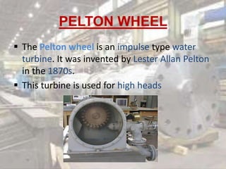
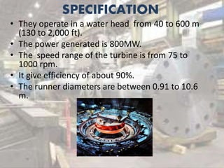
3.1] Pelton turbine
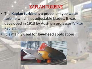
3.2] Kaplan turbine
3.3] Francis turbine
4] DIFFERENCE BETWEEN PELTON , KAPLAN ,
FRANCIS TURBINES.](https://image.slidesharecdn.com/hydraulicturbines-170212043632/85/Hydraulic-turbines-2-320.jpg)
![MAIN COMPONENTS
1] Nozzle and spear
2] Runner and bucket
3] Casing
4] Breaking jet
1] Nozzle :- It controls the amount of water striking
the vanes of runner.
2] Casing :- It is used to prevent splashing of
water.](https://image.slidesharecdn.com/hydraulicturbines-170212043632/85/Hydraulic-turbines-8-320.jpg)
![3] Runner and Bucket :- It is circular disc on the
periphery on which evenly spaced bucket are
fixed.
4] Breaking jet :- Its function is to stop the
runner in a short time period.](https://image.slidesharecdn.com/hydraulicturbines-170212043632/85/Hydraulic-turbines-9-320.jpg)

![SR NO. STATION POWER
GENERATED[MW]
1 AMBALA CANTT[INDIA] 800
2 BIEUDRON[SWISS] 1269
3 CASTAIC [US] 1500](https://image.slidesharecdn.com/hydraulicturbines-170212043632/85/Hydraulic-turbines-13-320.jpg)
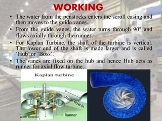
![THE MAIN COMPONENTS ARE :-
1] Scroll casing
2] Guide vanes
3] Draft tube
4] Runner
5] Hub
1] Scroll casing: It is the casing which guides the
water and control the water passage.
2] Guide vanes : It is the vanes which guide the
water and perform same function that by scroll.](https://image.slidesharecdn.com/hydraulicturbines-170212043632/85/Hydraulic-turbines-16-320.jpg)
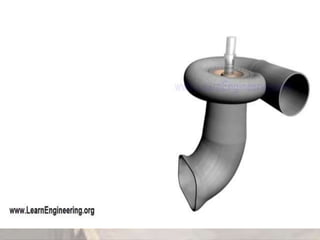
![3] Draft tube:- It discharges the water to trail
race through gradually expanding tube.
4] Runner :- It is connected to shaft of the
generator.
5] Hub:- It part on which runner is mounted](https://image.slidesharecdn.com/hydraulicturbines-170212043632/85/Hydraulic-turbines-17-320.jpg)
![APLLICATIONS
• The kaplan turbine is used in Indian.
SR
NO.
STATION POWER
GENERATED
[MW]
1. LPH 55
2. KADRA 150
3. KODASSALLI 120
4. ALMATTI 275](https://image.slidesharecdn.com/hydraulicturbines-170212043632/85/Hydraulic-turbines-20-320.jpg)

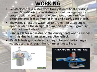
![THE MAIN PARTS ARE :-
1] Spiral casing
2] Guide vanes
3] Runners
4] Draft tube
1] Spiral casing :- It guides the water to the guide
vanes and also control the flow.
2] Guide vanes :- They guide the water to runner
and get closed on increase in flow.](https://image.slidesharecdn.com/hydraulicturbines-170212043632/85/Hydraulic-turbines-23-320.jpg)
![3] Runner :- They are heart of the turbine and
rotate on the impact of flow.
4] Draft tube :- It is place from where the water
is discharged from the turbine](https://image.slidesharecdn.com/hydraulicturbines-170212043632/85/Hydraulic-turbines-24-320.jpg)
![The Francis turbine are used in places
like:-
SR NO . PLACES POWER GENERATION
[MW]
1 Koyna IV (India) 250
2 Turkwell (Kenya) 53
3 Karun (Iran) 250
4 Three Gorges (China) 765](https://image.slidesharecdn.com/hydraulicturbines-170212043632/85/Hydraulic-turbines-27-320.jpg)
![DIFFERENCE BETWEEN
PELTON,KAPLAN,FRANCIS
PARAMETERS PELTON TURBINE KAPLAN TURBINE FRANCIS TURBINE
TYPE OF TURBINE IMPULSE TYPE PROPELLER TYPPE INWARD FLOW
REACTION TYPE
POWER GENRATION
[MW]
400 200 800
SPEED RATE[rpm] 65 - 800 70-429 75 -1000
EFFICIENCY[%] 85 80 90](https://image.slidesharecdn.com/hydraulicturbines-170212043632/85/Hydraulic-turbines-28-320.jpg)


![[PPT] on Steam Turbine](https://cdn.slidesharecdn.com/ss_thumbnails/spsharmafinalppt-140608082156-phpapp01-thumbnail.jpg?width=640&height=640&fit=bounds)


