Downloaded 104 times


![82
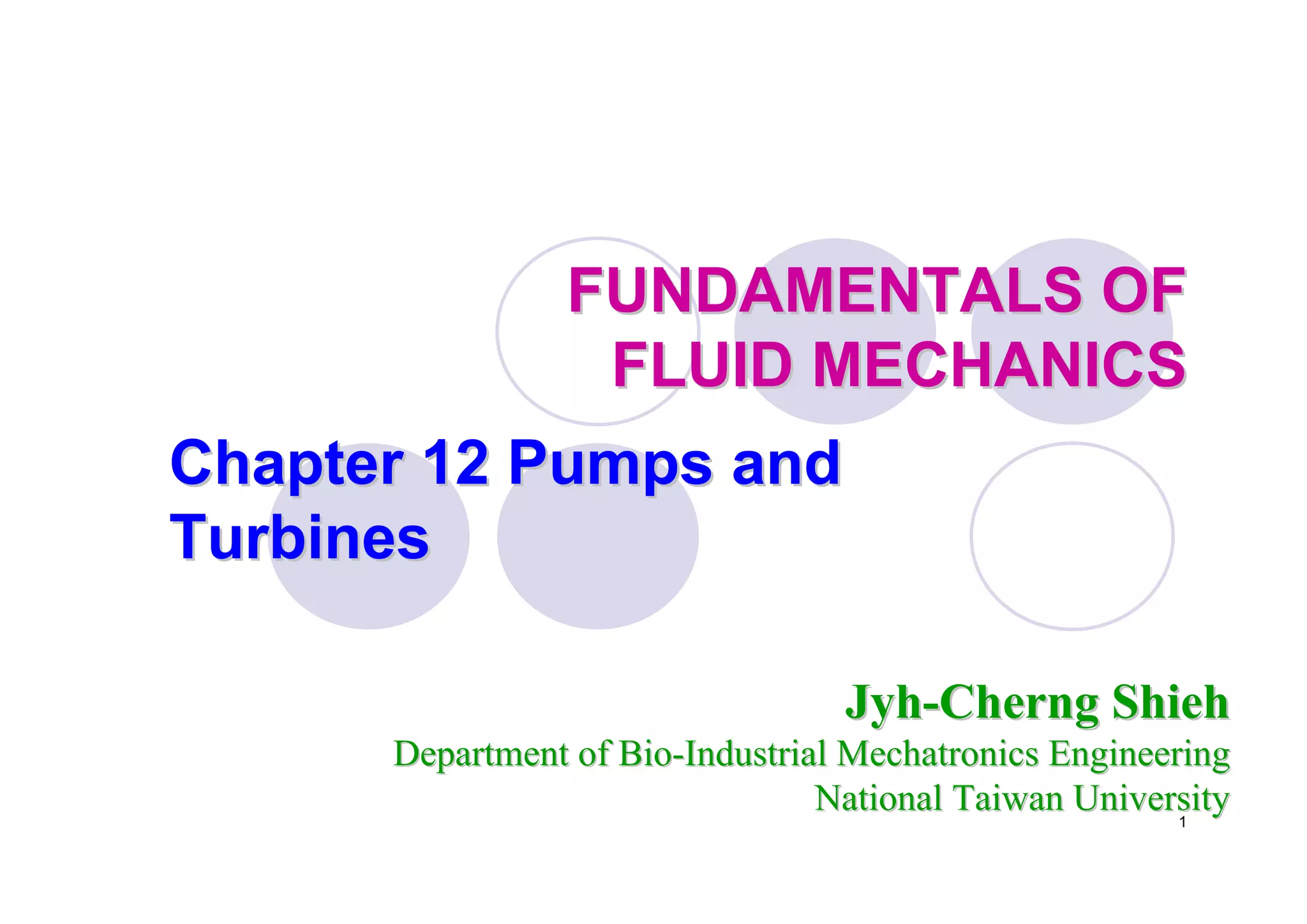
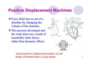
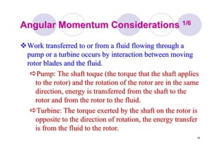
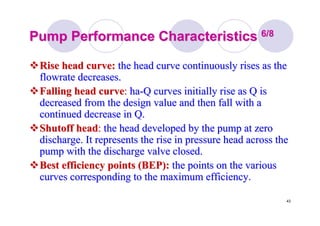
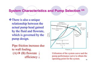
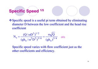
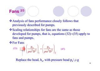
Specific SpeedSpecific Speed 2/52/5
For nay pump it is customary to specify a value of specificFor nay pump it is customary to specify a value of specific
speed at the flow coefficient corresponding to peakspeed at the flow coefficient corresponding to peak
efficiency only.efficiency only.
In the United States a modified, dimensional form ofIn the United States a modified, dimensional form of
specific speed,specific speed, NNsdsd
4/3
a
sd
)]ft(h[
)gpm(Q)rpm(
N
ω
= (44)(44)](https://image.slidesharecdn.com/fluid12-160423103849/85/Fluid-mechanics-82-320.jpg)
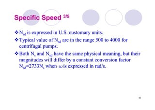
![86
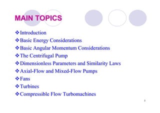
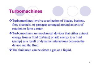
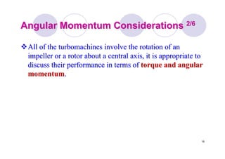
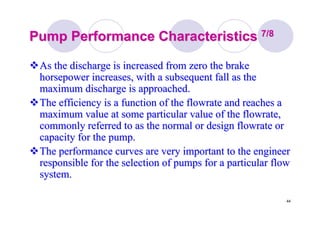
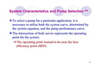
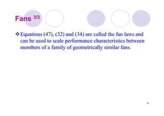
Suction Specific SpeedSuction Specific Speed 1/21/2
Suction specific speed is definedSuction specific speed is defined
In the United States a modified, dimensional form ofIn the United States a modified, dimensional form of
suction specific speed,suction specific speed, SSsdsd
4/3
R
s
)]NPSH(g[
Q
S
ω
= (45)(45)
4/3
R
sd
)]ft(NPSH[
)gpm(Q)rpm(
S
ω
= (44)(44)](https://image.slidesharecdn.com/fluid12-160423103849/85/Fluid-mechanics-86-320.jpg)

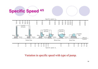
![129
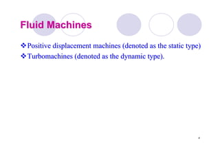
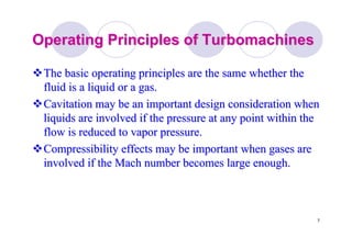
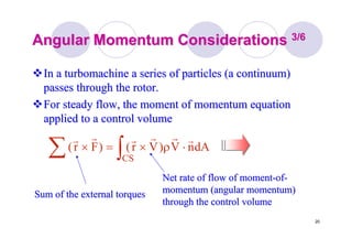
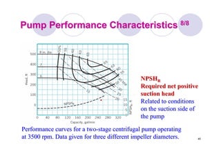
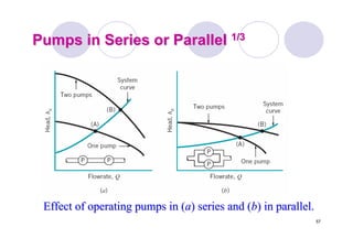
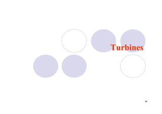
Power Specific SpeedPower Specific Speed 1/21/2
The design engineer has a variety of turbine typesThe design engineer has a variety of turbine types
available for any given application.available for any given application.
It is necessary to determine which type of turbine wouldIt is necessary to determine which type of turbine would
best fit the job before detailed design work is attempted.best fit the job before detailed design work is attempted.
As with pump, the use of a specific speed parameter canAs with pump, the use of a specific speed parameter can
help provide this informationhelp provide this information
4/5
T
shaft
s
)gh(
/W
'N
ρω
=
&
(53)(53)
4/5
T
shaft
sd
)]ft(h[
)bhp(W)rpm(
'N
&ω
=](https://image.slidesharecdn.com/fluid12-160423103849/85/Fluid-mechanics-129-320.jpg)

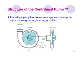
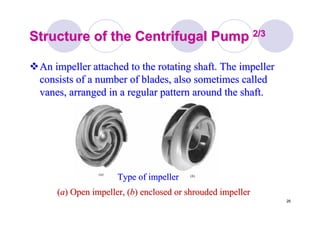
Pumps and turbines are fluid machines that either add energy to or extract energy from a fluid. Pumps add energy by doing work on the fluid, while turbines extract energy from the fluid as it does work on the turbine. Specifically, centrifugal pumps have an impeller and casing. The impeller adds energy to the fluid by increasing pressure and velocity as it rotates and throws the fluid outward. The casing then converts the kinetic energy into increased pressure before the fluid exits.


