1) The document provides an overview and objectives of a training package on fluid mechanics and flow through pipes for engineering students.
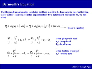
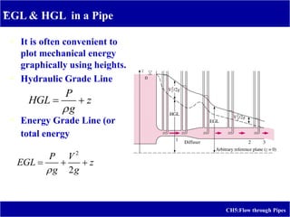
2) It includes the Bernoulli equation, energy grade line, hydraulic grade line, friction losses, minor losses, and piping networks.
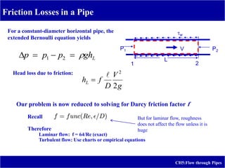
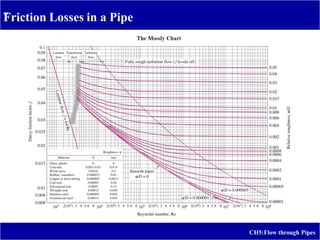
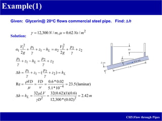
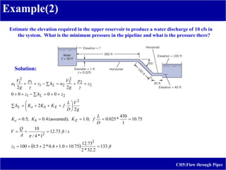
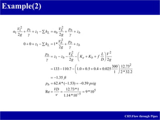
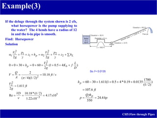
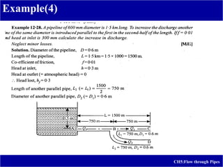
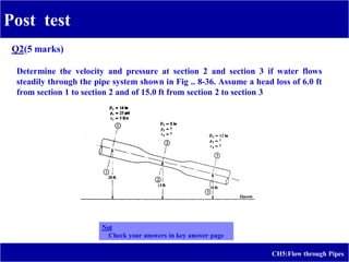
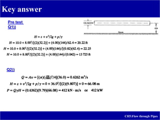
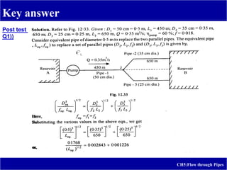
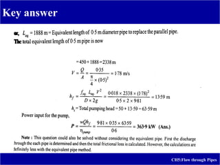
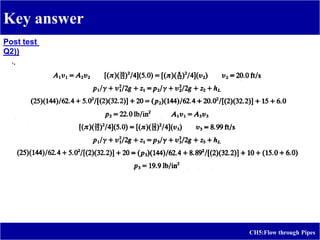
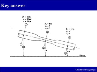
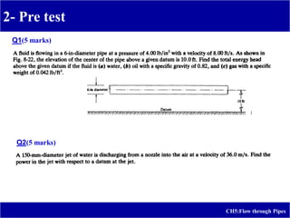
3) Example problems are provided to calculate head loss due to friction in laminar flow and estimate the elevation and pressures required for a given water discharge rate in a pipeline system.

![CH5:Flow through Pipes
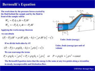
Bernoulli´s Equation
Consider a fluid flowing in a tube as shown in the figure
in a steady, incompressible, no viscous flow. We apply
the work-energy theorem to a sample of fluid initially
contained between point 1 and 2. During time Δt this
sample moves along the tube to the region between
points 1´and 2´. So,
Wall forces = ΔK [Change of kinetic Energy]
Wall forces include gravitational and pressure forces. We
neglecting internal frictional forces. Non-viscous flow.
No mechanical dissipation energy is considered.
Work of gravitational forces can be computed as the
variation of potential energy of sample. Considering the
continuity equation we can obtain
Change of kinetic energy of sample will be
Fluid moving in a pipe that varies in both height and
cross-sectional area. The net effect on the sample
during a time Δt is that a mass initially at height h1 and
speed v1 is transferred to a height h2 with speed v2
)
(
)
(
)
( 2
1
2
1 h
h
V
g
h
h
g
m
U
)
(
)
)(
( 2
1
2
2
2
1
2
1
2
2
2
1
v
v
V
v
v
m
K
](https://image.slidesharecdn.com/ch5flowthroughpipes-210407121102/85/Flow-through-pipes-8-320.jpg)
![CH5:Flow through Pipes
Bernoulli´s Equation
const
v
h
g
P
v
h
g
P
v
h
g
P
2
2
1
2
2
2
1
2
2
2
1
2
1
1
1
Remarks about Bernoulli Equation
g
v
h
g
P
const
g
v
h
g
P
2
2
2
2
2
Flow work or pressure energy; Is the portion of the potential energy term
that the fluid is capable of yielding of its sustained pressure. IS Unit: Joule
per Newton (meter). Dimension : Length
(1)
(2)
Potential energy, due to the gravitational field. IS Unit: meter
Each term having the same units (1) [Energy per unit
of volume] (2) [Energy per unit of weight].
Expression (1) can also be considered as energy per
volume flow rate, and (2) as energy per weight flow
rate
Kinetic energy. IS Unit: meter (Joule per Newton)](https://image.slidesharecdn.com/ch5flowthroughpipes-210407121102/85/Flow-through-pipes-10-320.jpg)