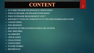
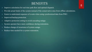
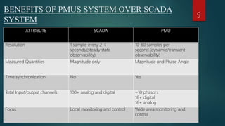
A SEMINAR BASED ON
PHASOR MEASUREMENT UNIT AND IT’S APPLICATIONS
SUBMITTED TO-
MR. PRAKASH KUMAR RAY
MS.SUMAN DAS
MS. PRACHITARA SATPATHY
MS. GARGI MOHAPATRA
DEPARTMENT OF ELECTRICAL ENGINEERING.
1
SUBMITTED BY-
KHURSHID PARWEZ
REDG.NO-1721106130,
SEMESTER-8TH SEM.,YEAR-4TH YEAR,
BRANCH-ELECTRICAL ENGINEERING.
 SYNCHRO PHASOR TECHNOLOGY: MOTIVATION
 WHAT IS PHASOR AND PHASOR ESTIMATION?
 WHAT IS PHASOR MEASUREMENT UNIT ?
 DIFFERENT TYPES OF COMPONENTS IN PMUOMS INFORMATION FLOW
 CONNECTIONS
 PMU BENEFITS
 BENEFITS OF PMUS SYSTEM OVER SCADA SYSTEM
 PMU PROVIDES
 ALGORITHM
 APPLICATION
 CHALLENGES
 CONCLUSION
 FUTURE WORKS
 REFERENCES
2
SYNCHRO PHASOR TECHNOLOGY: MOTIVATION
 Several blackouts all over the world , e.g. US North-Eastern blackout in August 2003; July
2012 blackout in India.
 The SCADA system not suitable for real time controls/time critical applications.
 Data time skewed. Data scan rate up to 10 sec.
 Only magnitude measurements and phasors through state estimation-time extensive.
 Recent Smart Grid Initiative - Synchro phasors form an important part.
 Consists of Phasor Measurement Units (PMUs) in the field and Phasor Data Concentrator
(PDC).
 PMUs can provide time stamped phasor information every few millisecond.
3
WHAT IS PHASOR AND PHASOR ESTIMATION?
A phasor can be defined as a complex number which can represented any sinusoidal signal.
 The magnitude of the complex number provides the rms value of the signal.
 Angle of the phasor provides the instantaneous position of the signal on wt axis.
Phasor Estimation: - It involves in estimating the instantaneous angle and the rms value of the signal.
4
WHAT IS PHASOR MEASUREMENT UNIT ?
 The phasor measurement unit (PMU) is a microprocessor based device that uses the ability of
digital signal processors in order to measure 50/60 Hz AC waveforms (voltages and currents)
at a typical rate of 48 samples per cycle (2400/2880 samples per second).
 PMU uses digital signal processing techniques to calculate the voltage and current phasors.
 The measured phasors are tagged by GPS time stamps and are transmitted to a PDC at the
rates 30-60 samples per second.
5
ANALOG
INPUTS
6
DIFFERENT TYPES OF COMPONENTS IN PMU
CONNECTIONS 7
BENEFITS
 Improve calculation for real time path flow and optimal dispatch.
 Provide actual limits of the system instead of the conservative ones from offline calculations.
 Easier to understand sequence of events when using synchronized data from PMU.
 Improved backup protection.
 Adaptive protection setting to avoid cascading outage.
 System operator have more confidence during restoration.
 Reduce change of recurrence of system outage.
 Reduce time needed for a system restoration.
8
BENEFITS OF PMUS SYSTEM OVER SCADA
SYSTEM
ATTRIBUTE SCADA PMU
Resolution 1 sample every 2-4
seconds.(steady state
observability)
10-60 samples per
second.(dynamic/transient
observability)
Measured Quantities Magnitude only Magnitude and Phase Angle
Time synchronization No Yes
Total Input/output channels 100+ analog and digital ~10 phasors
16+ digital
16+ analog
Focus Local monitoring and control Wide area monitoring and
control
9
PMU PROVIDES
 They provide positive sequence voltage and current measurements synchronized to within a
microsecond.
 Also measure local frequency and rate of change of frequency.
 May be customized to measure harmonics, negative and zero sequence quantities, as well as
individual phase voltages and currents.
10
YES
11
.
NO
Depth First Algorithm for PMU Placement
APPLICATIONS OF PMU
 Angle and Frequency Monitoring
 Transmission Fault Location and Estimation
 Control of WAMS
 Traveling wave fault detection
12
CHALLENGES
 Visualization of PMU data – Difficult to visualize and manage large amounts of data.
 Communication of PMU data – Expensive communication network required.
 Optimal Placing of PMU’s.
 High investment.
 Diverse requirements from the utilities.
 Communication delays.
13
CONCLUSION
 From this dissertation work it can be concluded that Application of Synchronized Phasor
measurement Improves the current monitoring and controlling SCADA system.
 Various PMU Placement Algorithm are implemented with the Aim of achieving complete
observability of network.
 PMU can be very useful in application of Power system protection.
14
FUTURE SCOPE
 This dissertation work can be further extended for various applications in power system
protection. Relay co-ordination using synchro phasor and Adaptive power system protection
scheme is the new area for which this project work can be helpful.
 State Estimation and Intelligent load shedding application is possible with Time
synchronized measurements.
15
REFERENCES
 IEEE Standard for Synchro phasors for Power Systems (IEEE Std C37.118 - 2005).
 Phadke, A.G., Kasztenny, B., “Synchronized phasor and frequency measurement under
transient conditions”, IEEE Transactions on Power Delivery, Vol. 24, No. 1, December 2008
 “Huang J, Wine. Fault-tolerant placement of phasor measurement units based on control
reconfigurability. Control Eng. Pract 2013; 21:1–11...
 Kumar Jitender, Rai J.N., Hasan Naimul, “Use of Phasor Measurement Unit (PMU) for Large
Scale Power System State Estimation”, 2012 IEEE fifth India International Conference on
Power Electronics, IICPE2012, Delhi Technological University, New Delhi, India, ISSN:
2160-3162, Print ISBN: 978-1-4673-0931-8, December – 2012, pp. 1-5.
 Nuki, R.F. and Phadke, A.G., “Phasor measurement placement techniques for complete and
incomplete observability”, IEEE Transactions on Power Delivery, Vol. 20, No. 4, October
2005, pp 2381–2388.
 D.Tholomier, HKang, BCvorovic,” Phasor Measurements Functionality and Applications”,
Power Systems Conference 2009, Clemson University Advanced Metering, Protection,
Control, Communication and Distributed Resources.
16
17

Phasor measurement unit and it's application ppt

  • 1.
    A SEMINAR BASEDON PHASOR MEASUREMENT UNIT AND IT’S APPLICATIONS SUBMITTED TO- MR. PRAKASH KUMAR RAY MS.SUMAN DAS MS. PRACHITARA SATPATHY MS. GARGI MOHAPATRA DEPARTMENT OF ELECTRICAL ENGINEERING. 1 SUBMITTED BY- KHURSHID PARWEZ REDG.NO-1721106130, SEMESTER-8TH SEM.,YEAR-4TH YEAR, BRANCH-ELECTRICAL ENGINEERING.
  • 2.
     SYNCHRO PHASORTECHNOLOGY: MOTIVATION  WHAT IS PHASOR AND PHASOR ESTIMATION?  WHAT IS PHASOR MEASUREMENT UNIT ?  DIFFERENT TYPES OF COMPONENTS IN PMUOMS INFORMATION FLOW  CONNECTIONS  PMU BENEFITS  BENEFITS OF PMUS SYSTEM OVER SCADA SYSTEM  PMU PROVIDES  ALGORITHM  APPLICATION  CHALLENGES  CONCLUSION  FUTURE WORKS  REFERENCES 2
  • 3.
    SYNCHRO PHASOR TECHNOLOGY:MOTIVATION  Several blackouts all over the world , e.g. US North-Eastern blackout in August 2003; July 2012 blackout in India.  The SCADA system not suitable for real time controls/time critical applications.  Data time skewed. Data scan rate up to 10 sec.  Only magnitude measurements and phasors through state estimation-time extensive.  Recent Smart Grid Initiative - Synchro phasors form an important part.  Consists of Phasor Measurement Units (PMUs) in the field and Phasor Data Concentrator (PDC).  PMUs can provide time stamped phasor information every few millisecond. 3
  • 4.
    WHAT IS PHASORAND PHASOR ESTIMATION? A phasor can be defined as a complex number which can represented any sinusoidal signal.  The magnitude of the complex number provides the rms value of the signal.  Angle of the phasor provides the instantaneous position of the signal on wt axis. Phasor Estimation: - It involves in estimating the instantaneous angle and the rms value of the signal. 4
  • 5.
    WHAT IS PHASORMEASUREMENT UNIT ?  The phasor measurement unit (PMU) is a microprocessor based device that uses the ability of digital signal processors in order to measure 50/60 Hz AC waveforms (voltages and currents) at a typical rate of 48 samples per cycle (2400/2880 samples per second).  PMU uses digital signal processing techniques to calculate the voltage and current phasors.  The measured phasors are tagged by GPS time stamps and are transmitted to a PDC at the rates 30-60 samples per second. 5
  • 6.
  • 7.
  • 8.
    BENEFITS  Improve calculationfor real time path flow and optimal dispatch.  Provide actual limits of the system instead of the conservative ones from offline calculations.  Easier to understand sequence of events when using synchronized data from PMU.  Improved backup protection.  Adaptive protection setting to avoid cascading outage.  System operator have more confidence during restoration.  Reduce change of recurrence of system outage.  Reduce time needed for a system restoration. 8
  • 9.
    BENEFITS OF PMUSSYSTEM OVER SCADA SYSTEM ATTRIBUTE SCADA PMU Resolution 1 sample every 2-4 seconds.(steady state observability) 10-60 samples per second.(dynamic/transient observability) Measured Quantities Magnitude only Magnitude and Phase Angle Time synchronization No Yes Total Input/output channels 100+ analog and digital ~10 phasors 16+ digital 16+ analog Focus Local monitoring and control Wide area monitoring and control 9
  • 10.
    PMU PROVIDES  Theyprovide positive sequence voltage and current measurements synchronized to within a microsecond.  Also measure local frequency and rate of change of frequency.  May be customized to measure harmonics, negative and zero sequence quantities, as well as individual phase voltages and currents. 10
  • 11.
  • 12.
    APPLICATIONS OF PMU Angle and Frequency Monitoring  Transmission Fault Location and Estimation  Control of WAMS  Traveling wave fault detection 12
  • 13.
    CHALLENGES  Visualization ofPMU data – Difficult to visualize and manage large amounts of data.  Communication of PMU data – Expensive communication network required.  Optimal Placing of PMU’s.  High investment.  Diverse requirements from the utilities.  Communication delays. 13
  • 14.
    CONCLUSION  From thisdissertation work it can be concluded that Application of Synchronized Phasor measurement Improves the current monitoring and controlling SCADA system.  Various PMU Placement Algorithm are implemented with the Aim of achieving complete observability of network.  PMU can be very useful in application of Power system protection. 14
  • 15.
    FUTURE SCOPE  Thisdissertation work can be further extended for various applications in power system protection. Relay co-ordination using synchro phasor and Adaptive power system protection scheme is the new area for which this project work can be helpful.  State Estimation and Intelligent load shedding application is possible with Time synchronized measurements. 15
  • 16.
    REFERENCES  IEEE Standardfor Synchro phasors for Power Systems (IEEE Std C37.118 - 2005).  Phadke, A.G., Kasztenny, B., “Synchronized phasor and frequency measurement under transient conditions”, IEEE Transactions on Power Delivery, Vol. 24, No. 1, December 2008  “Huang J, Wine. Fault-tolerant placement of phasor measurement units based on control reconfigurability. Control Eng. Pract 2013; 21:1–11...  Kumar Jitender, Rai J.N., Hasan Naimul, “Use of Phasor Measurement Unit (PMU) for Large Scale Power System State Estimation”, 2012 IEEE fifth India International Conference on Power Electronics, IICPE2012, Delhi Technological University, New Delhi, India, ISSN: 2160-3162, Print ISBN: 978-1-4673-0931-8, December – 2012, pp. 1-5.  Nuki, R.F. and Phadke, A.G., “Phasor measurement placement techniques for complete and incomplete observability”, IEEE Transactions on Power Delivery, Vol. 20, No. 4, October 2005, pp 2381–2388.  D.Tholomier, HKang, BCvorovic,” Phasor Measurements Functionality and Applications”, Power Systems Conference 2009, Clemson University Advanced Metering, Protection, Control, Communication and Distributed Resources. 16
  • 17.