Downloaded 25 times


![14
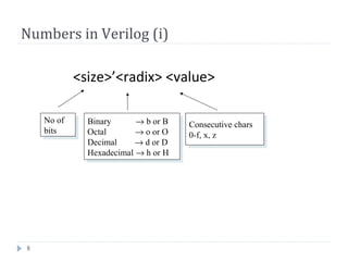
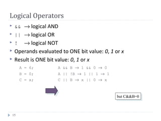
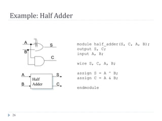
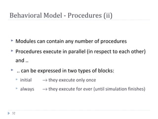
Vectors
Represent buses
wire [3:0] busA;
reg [1:4] busB;
reg [1:0] busC;
Left number is MS bit
Slice management
busC[1] = busA[2];
busC[0] = busA[1];
busC = busA[2:1]; ⇔](https://image.slidesharecdn.com/verilogforlab-140706233943-phpapp02/85/Verilogforlab-14-320.jpg)


![20
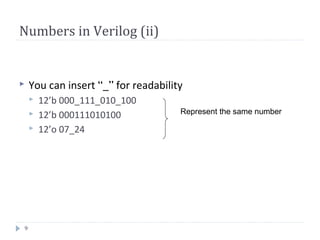
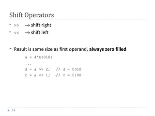
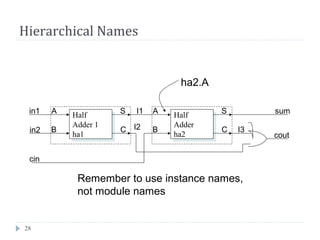
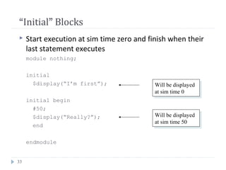
Concatenation Operator
{op1, op2, ..} → concatenates op1, op2, .. to single number
Operands must be sized !!
reg a;
reg [2:0] b, c;
..
a = 1’b 1;
b = 3’b 010;
c = 3’b 101;
catx = {a, b, c}; // catx = 1_010_101
caty = {b, 2’b11, a}; // caty = 010_11_1
catz = {b, 1}; // WRONG !!
Replication ..
catr = {4{a}, b, 2{c}}; // catr = 1111_010_101101](https://image.slidesharecdn.com/verilogforlab-140706233943-phpapp02/85/Verilogforlab-20-320.jpg)


![39
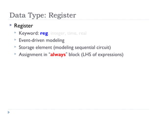
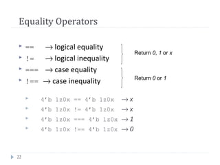
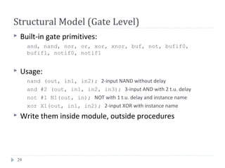
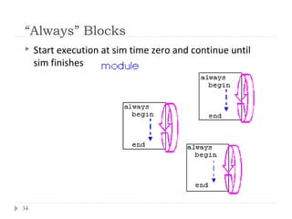
Procedural Statements: if
if (expr1)
true_stmt1;
else if (expr2)
true_stmt2;
..
else
def_stmt;
E.g. 4-to-1 mux:
module mux4_1(out, in, sel);
output out;
input [3:0] in;
input [1:0] sel;
reg out;
wire [3:0] in;
wire [1:0] sel;
always @(in or sel)
if (sel == 0)
out = in[0];
else if (sel == 1)
out = in[1];
else if (sel == 2)
out = in[2];
else
out = in[3];
endmodule](https://image.slidesharecdn.com/verilogforlab-140706233943-phpapp02/85/Verilogforlab-39-320.jpg)
![40
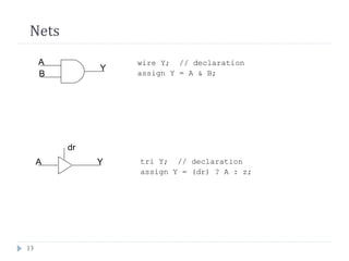
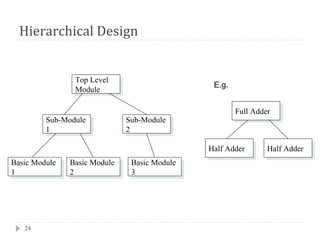
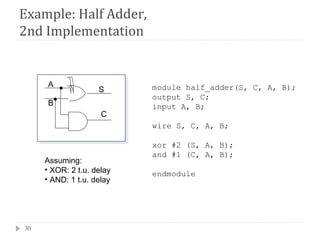
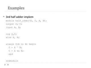
Procedural Statements: case
case (expr)
item_1, .., item_n: stmt1;
item_n+1, .., item_m: stmt2;
..
default: def_stmt;
endcase
E.g. 4-to-1 mux:
module mux4_1(out, in, sel);
output out;
input [3:0] in;
input [1:0] sel;
reg out;
wire [3:0] in;
wire [1:0] sel;
always @(in or sel)
case (sel)
0: out = in[0];
1: out = in[1];
2: out = in[2];
3: out = in[3];
endcase
endmodule](https://image.slidesharecdn.com/verilogforlab-140706233943-phpapp02/85/Verilogforlab-40-320.jpg)
![Thanasis OikonomouVerilog HDL Basics42
Compiler Directives
`include “filename” → inserts contents of file into current file; write it
anywhere in code ..
`define <text1> <text2> → text1 substitutes text2;
e.g. `define BUS reg [31:0] in declaration part: `BUS data;
`timescale <time unit>/<precision>
e.g. `timescale 10ns/1ns later: #5 a = b;
50ns50ns](https://image.slidesharecdn.com/verilogforlab-140706233943-phpapp02/85/Verilogforlab-42-320.jpg)


![bin2gray.v
module bin2gray ( B ,G );
input [3:0] B ;
wire [3:0] B ;
output [3:0] G ;
wire [3:0] G ;
assign G[3] = B[3];
assign G[2:0] = B[3:1] ^ B[2:0];
endmodule
Convert Binary to Gray:
Copy the most significant bit.
For each smaller i
G[i] = B[i+1] ^ B[i]](https://image.slidesharecdn.com/verilogforlab-140706233943-phpapp02/85/Verilogforlab-46-320.jpg)
![Binary coding {0...7}: {000, 001, 010, 011, 100, 101, 110, 111}
Gray coding {0...7}: {000, 001, 011, 010, 110, 111, 101, 100}
Binary - Gray Code
ConversionsGray code: G[i], i = n – 1 : 0
Binary code: B[i], i = n – 1 : 0
Convert Binary to Gray:
Copy the most significant bit.
For each smaller i
G[i] = B[i+1] ^ B[i]
Convert Gray to Binary:
Copy the most significant bit.
For each smaller i
B[i] = B[i+1] ^ G[i]](https://image.slidesharecdn.com/verilogforlab-140706233943-phpapp02/85/Verilogforlab-47-320.jpg)
![Gray Code
000 000
001 001
010 011
011 010
100 110
101 111
110 101
111 100
Binary
B[2:0]
Gray Code
G[2:0]
Gray code to Binary
B[2] = G[2];
B[1:0] = B[2:1] ^ G[1:0];](https://image.slidesharecdn.com/verilogforlab-140706233943-phpapp02/85/Verilogforlab-48-320.jpg)
![module gray2bin6 ( G ,B );
input [5:0] G ;
wire [5:0] G ;
output [5:0] B ;
wire [5:0] B ;
assign B[5] = G[5];
assign B[4:0] = B[5:1] ^ G[4:0];
endmodule
B(msb) = G(msb);
for(j = msb-1; j >= 0; j=j-1)
B(j) = B(j+1) ^ G(j);
Gray code to Binary](https://image.slidesharecdn.com/verilogforlab-140706233943-phpapp02/85/Verilogforlab-49-320.jpg)
![gray2bin.v
module gray2bin ( G ,B );
input [3:0] G ;
wire [3:0] G ;
output [3:0] B ;
reg [3:0] B ;
integer i;
always @(G)
begin
B[3] = G[3];
for(i=2; i >= 0; i = i-1)
B[i] = B[i+1] ^ G[i];
end
endmodule
Convert Gray to Binary:
Copy the most significant bit.
For each smaller i
B[i] = B[i+1] ^ G[i]](https://image.slidesharecdn.com/verilogforlab-140706233943-phpapp02/85/Verilogforlab-50-320.jpg)

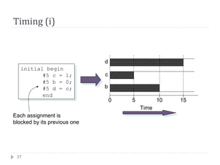
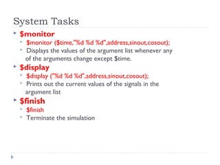
Verilog is a hardware description language used to model and simulate digital circuits. It supports different levels of abstraction from algorithmic level down to transistor level. The document describes key Verilog concepts including data types, operators, procedural blocks, timing, and system tasks. It also explains the use of modules for hierarchical design and compiler directives for code reuse and timescale specification.