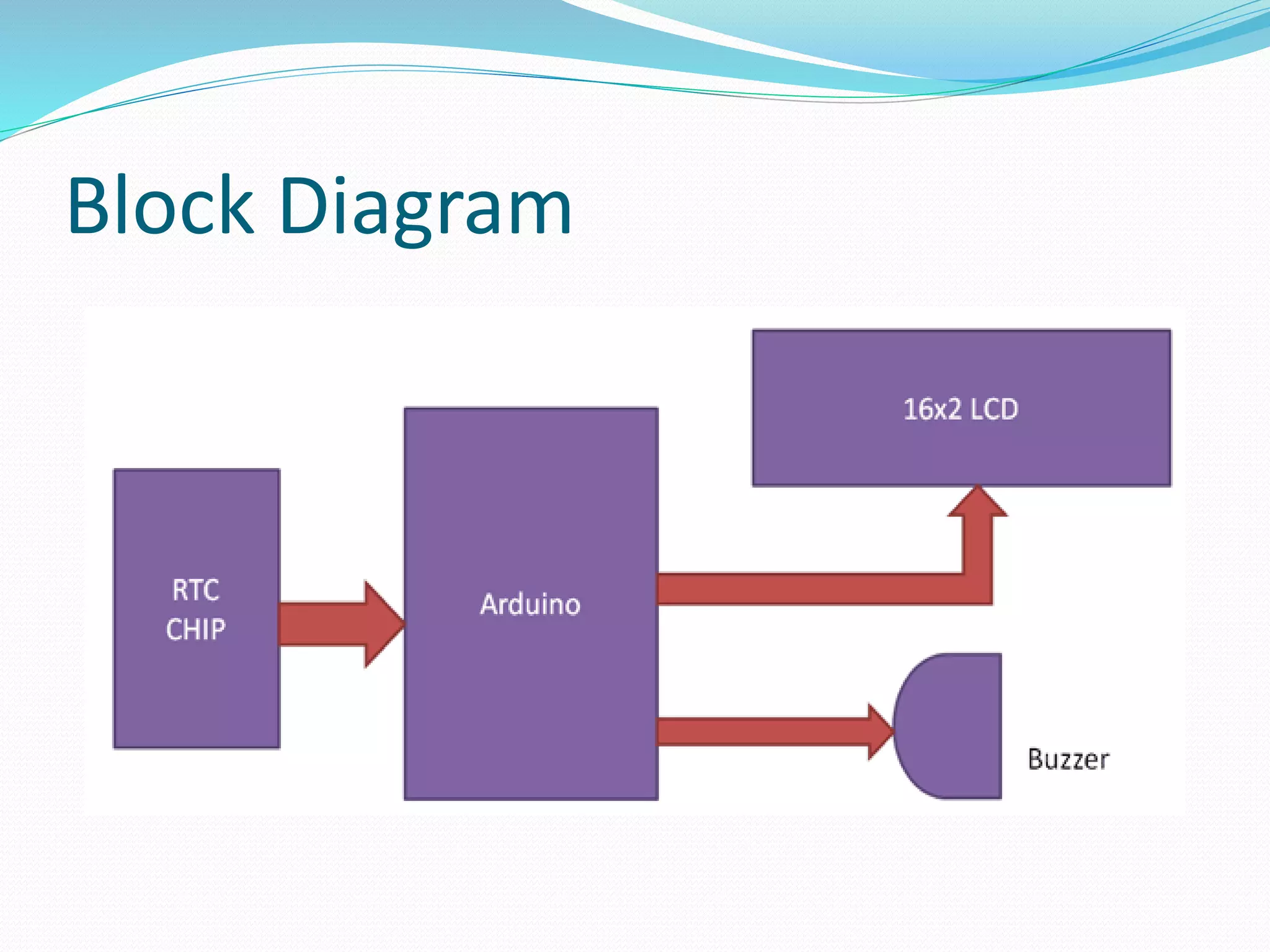
The document summarizes a presentation on AVR microcontrollers. It discusses the AVR family of microcontrollers, highlighting their RISC architecture, 32 general purpose registers, and single cycle instruction execution. It also covers new AVR features, application specific AVRs for tasks like motor control, USB, and CAN, and automotive-qualified AVRs using CMOS process technology.
This document describes the features and specifications of the ATmega32 8-bit microcontroller. It includes details on the microcontroller's architecture such as its AVR CPU core, 32K bytes of flash memory, 1024 bytes of EEPROM, 2K bytes of SRAM, and various peripherals. It also provides information on the microcontroller's pins and packages, operating voltages, speed grades, and power consumption. The document is intended to provide an overview of the capabilities and technical specifications of the ATmega32 microcontroller.
Now-a-days, a growing number of people in a developing countries like India forces to look for new solutions for the continuous monitoring of health check-up. It has become a necessity to visit hospitals frequently for doctor’s consultation, which has become financially related and a time consuming process. To overcome this situation, we propose a design to monitor the patient’s health conditions such as heart beat, temperature, ECG and BP and send the message to guardian using GSM. In the recent development of internet of things(IoT) makes all objects interconnected and been recognized as the next technical revolution. Patient monitoring is one of the IoT application to monitor the patient health status. Internet of things makes medical equipments more efficient by allowing real time monitoring of health. Using IoT doctor can continuously monitor the patient’s on his smart phone and also the patient history will be stored on the web server and doctor can access the information whenever needed from anywhere.
This project displays the current time and temperature using an Arduino board, LM35 temperature sensor, and DS1307 RTC module. The LM35 and DS1307 are connected to analog pins on the Arduino, which uses its onboard ADC to read the analog voltage values and display the converted time and temperature readings on an LCD screen. The key components required are the Arduino, sensors, LCD, and supporting electronics. The document provides details on how each component functions and how they interconnect and cooperate to continuously display the time and surrounding temperature.
Microcontrollers are small computers that integrate RAM, ROM, I/O ports and other components onto a single chip. They are used in applications where cost, power and space are critical. The document compares microprocessors and microcontrollers, noting that microcontrollers have all components on one chip while microprocessors have separate chips. It then describes the typical internal blocks of a microcontroller, including the CPU, memory, I/O ports, timers and serial ports. Block diagrams show the connections between these internal components.
The document discusses the 8051 microcontroller, including its architecture, pin configuration, memory organization, timers, interrupts, and interfacing capabilities. It describes the 8051's features like on-chip RAM, ROM, timers and low power consumption which make it suitable for control applications. The document outlines the differences between microprocessors and microcontrollers, and covers various interfacing examples like switches, LEDs, 7-segment displays, LCDs, ADCs and relay interfacing. It concludes with common applications of the 8051 such as in automobiles, industrial processing, robotics and consumer electronics.
Blinking Of LEDs On LPC2148 ARM 7 TDMIS Based MicrocontrollerOmkar Rane
This document describes an experiment to program an LED to blink at regular intervals using an LPC2148 microcontroller. It discusses the objectives, equipment, theory of operation including the microcontroller's bus structure, PLL, and peripherals. It provides the algorithm, sample code to blink an LED, and shows the output of the compiled hex file and blinking LED. The goal is to learn to interface and program the microcontroller's GPIO pins to control an LED.
The document describes the 8051 microcontroller, its features which include 4 I/O ports, 2 timers, serial communication interface, and interrupts. It discusses the internal architecture such as memory organization, registers, and oscillator circuit. The document also provides details on the ports, timers, serial communication, and power modes of the 8051 microcontroller.
The document provides an introduction and overview of the Intel 8096 microcontroller. It discusses the 8096's salient features such as its 16-bit architecture, high-speed I/O capabilities, and uses in motor control and robotics. It describes the 8096's architecture including its 16-bit CPU, registers, memory mapping, and I/O features such as timers, serial port, and A/D converter. The document provides details on the 8096's instruction set, addressing modes, and interrupt structure.
Timer programming in assembly and C is discussed. Timers can be used to generate time delays or count external events by incrementing an internal counter register. Programs are provided to toggle ports with delays using Timer0 in normal mode, toggle a pin every 70us using Timer0 and 1:8 prescaler, and extend Timer1 to a 16-bit counter to count external pulses. Assembly code is given to generate a 12.5us square wave on a pin using Timer0 delays.
This document describes a home automation project that allows controlling home appliances like a TV, refrigerator, and lights using a personal computer. A PC is interfaced with a microcontroller via an RS232 cable. The microcontroller is connected to relays that switch appliances on and off. Home automation provides network connectivity between computers, appliances, and subsystems like HVAC and security. The project allows remote control and monitoring of appliances for convenience and energy savings.
This presentation discusses the details of the I2C protocol and interfacing of EEPROM with 8051 based on I2C protocol. It also discusses the other applications of I2C protocol
The document describes an 8051-based digital clock application that uses timers and interrupts. It configures Timer 0 to generate interrupts every 50ms by overflowing every 46080 cycles. Timer 1 is used to generate a 19200 baud rate for a serial port. On each Timer 0 interrupt, the clock display is updated. By generating interrupts every 50ms and counting 20 of them for 1 second, the timer configuration provides an approximate 1 second timer without exceeding the 8051's 65536 cycle limit.
Hardware debugging involves monitoring signals, checking connections between components, and testing circuit continuity on a target board. This process identifies issues like dry soldering, missing connections, or unnoticed PCB errors that could prevent firmware from functioning properly. Key tools for hardware debugging include a magnifying glass for visual inspection of soldering and tracks, a multimeter for checking continuity and signal values, an oscilloscope for analyzing waveforms and noise, a logic analyzer for capturing digital data, and a function generator for simulating input signals.
Temperature based fan speed control & monitoring usingJagannath Dutta
Our object of making this project is for reducing the power consumption. And also to assist people who are disabled and are unable to control the speed of fan.
Arduino for beginners- Introduction to Arduino (presentation) - codewithgauriGaurav Pandey
The document provides an overview of the Arduino platform for beginners. It defines Arduino as an open-source platform used for building electronics projects. All Arduino boards contain a microcontroller, which is a small computer. It then describes some popular Arduino boards like the Uno, Nano, Due, and Mega and their key specs and applications. The document proceeds to explain the main components of an Arduino Uno board such as the power supply, USB port, microcontroller, analog and digital pins. It provides details on the functions of these components and how they enable the Arduino board to operate.
This document presents an automatic bell ringing system using a microcontroller. The system uses a step-down transformer to power the microcontroller and other components. An LCD screen displays the time and schedule. A buzzer sounds according to the programmed schedule, such as every hour. The system is designed to automatically ring a bell in schools and colleges to avoid human errors. It has applications in education, industry, and other areas where an automatic scheduling system is needed.
This document provides an overview of the Arduino Uno microcontroller board. It defines a microcontroller as a single-chip computer containing a CPU, memory, and input/output interfaces. The Arduino is an open-source electronics platform with easy-to-use hardware and software that allows anyone to develop interactive electronic projects. Key specifications of the Arduino Uno board are provided, including its microcontroller chip, memory, analog and digital pins. The process of analog to digital conversion is explained. Basic Arduino programming concepts like data types, statements, operators, and control structures are covered. The bare minimum code structure of setup() and loop() functions is described.
water level controller using 8051 microcontrollerPrachi Pandey
This document presents a project on a water level controller using an 8051 microcontroller. It contains an introduction describing how the system monitors and controls water level in an overhead tank. The circuit components section lists the main hardware used, including an 8051 microcontroller, LCD, transistors, resistors, and motor. It also provides details on the transistor, resistor, and LCD. The circuit diagram and algorithm are presented. The working explains how different water levels are detected and the motor/display are controlled accordingly. Advantages of the system reducing human effort and consuming less power are highlighted. Applications include use in homes, buildings, and industries for automatic water level control.
Automatic room temperature controlled fan using arduino uno microcontrollerMohammod Al Emran
This paper presents the designs and the simulation of a DC fan control system based on room temperature using pulse width modulation technique, humidity and temperature sensor namely DHT11 with Arduino Uno Microcontroller. The fan will be used to reduce temperature of a room at certain level. To build the fan, we will use DTH11 Humidity Sensor. The sensor will measure the temperature continuously. When the temperature gets higher from a specific temperature, the fan will be on “On” mode. The speed of the fan will be determined by pwm using pulse-width modulation. The temperature along with the speed of the fan will be displayed through LCD monitor.
The document discusses timer modules and pulse width modulation (PWM) on Atmega microcontrollers. It describes the different timer modules, including an 8-bit and 16-bit timer/counter with options like prescaling and compare/capture modes. It explains timer overflow, compare match, and input capture events. It then provides details on timer/counter 0, including its registers and modes like CTC PWM and fast PWM for generating PWM signals on an output pin.
Arduino based heartbeat monitoring system.Arkadeep Dey
Technological innovations in the field of disease prevention and maintenance of patient health have enabled the evolution of fields such as monitoring systems. Heart rate is a very vital health parameter that is directly related to the soundness of the human cardiovascular system. Heart rate is the number of times the heart beats per minute, reflects different physiological conditions such as biological workload, stress at work and concentration on tasks, drowsiness and the active state of the autonomic nervous system. It can be measured either by the ECG waveform or by sensing the pulse - the rhythmic expansion and contraction of an artery as blood is forced through it by the regular contractions of the heart. The pulse can be felt from those areas where the artery is close to the skin. This paper describes a technique of measuring the heart rate through a fingertip and Arduino. It is based on the principal of photophelthysmography (PPG) which is non-invasive method of measuring the variation in blood volume in tissue using a light source and detector. While the heart is beating, it is actually pumping blood throughout the body, and that makes the blood volume inside the finger artery to change too. This fluctuation of blood can be detected through an optical sensing mechanism placed around the fingertip. The signal can be amplified and is sent to Arduino with the help of serial port communication. With the help of processing software heart rate monitoring and counting is performed. The sensor unit consists of an infrared light-emitting-diode (IR LED) and a photo diode. The IR LED transmits an infrared light into the fingertip, a part of which is reflected back from the blood inside the finger arteries. The photo diode senses the portion of the light that is reflected back. The intensity of reflected light depends upon the blood volume inside the fingertip. So, every time the heart beats the amount of reflected infrared light changes, which can be detected by the photo diode. With a high gain amplifier, this little alteration in the amplitude of the reflected light can be converted into a pulse.
This document discusses various serial communication protocols used in embedded systems including RS-232, RS-485, I2C, SPI, CAN, and USB. It provides details on the voltage levels, maximum speeds, cable lengths, and other specifications of each protocol. It explains how differential signaling and twisted pair cables allow RS-485 to communicate over longer distances and faster speeds compared to RS-232.
The Arduino Uno is a microcontroller board based on the ATmega328 with 14 digital input/output pins, 6 analog inputs, a USB connection, and a power jack. It contains everything needed to support the microcontroller and can be programmed using the Arduino IDE. The Uno differs from previous boards by using an Atmega8U2 as a USB-to-serial converter instead of an FTDI chip. It is the latest and reference version of the Arduino platform.
Timers on PIC18 microcontrollers can be used to generate time delays. The PIC18 has 2-5 timers that are each 16-bits wide and accessed through two 8-bit registers. Timers can be programmed in assembly to count the internal clock or external pulses. Common steps to program Timer0 as a 16-bit timer include loading the registers, starting the timer, monitoring the overflow flag, stopping the timer, and clearing the flag. Examples are provided to toggle a port pin with a delay using Timer0 and Timer1 in different modes.
This document discusses interrupts in the Atmega328P microcontroller. It describes asynchronous I/O operation using interrupts versus polling. Interrupts allow the microcontroller to perform other tasks while waiting for an I/O device to signal that it is ready. When an interrupt occurs, the microcontroller saves its state and jumps to an interrupt service routine to handle the device, then returns to its original task. The Atmega328P has multiple interrupt vectors that can be enabled or disabled individually using various register bits to control interrupts from different pins and peripherals. Example C code is provided to configure an interrupt-driven program from the INT0 pin.
This document summarizes an Arduino seminar report. It discusses what Arduino is, different Arduino boards, how the Arduino board works including the controller, power supply, and USB to serial converter. It also summarizes sensors that can interface with Arduino like temperature sensors and hall sensors. Finally, it provides an overview of a home automation project using Arduino and GSM to control devices remotely through SMS messages.
This project report describes an Arduino-based time and temperature display. The project uses an Arduino board interfaced with an LM35 temperature sensor to measure temperature and display it on an LCD. An RTC DS1307 module is also interfaced to measure the current time and display it along with the temperature on the LCD. The report provides details of the components used, circuit diagram, programming code and working of the project to continuously display current time and temperature.
This document describes a heart rate monitoring system using an Arduino. It discusses using a pulse sensor to detect heartbeats which are then sent to an Arduino Uno microcontroller. The Arduino calculates beats per minute over 10 seconds and displays it on an LCD screen. Potential benefits are monitoring heart health for those at risk of heart attacks. It outlines the hardware, components, schematics and programming involved. Future applications discussed include integrating ECG measurements into a wearable smart t-shirt.
Countdown Timer Circuit Diagram with 7 Segment DisplayImran Risal
This document provides details on designing and building a countdown timer circuit using a 7-segment display and IC 4026 chips. It includes:
- An overview of the components used, including a breadboard, buzzer, Arduino Nano, 7-segment display, battery, IC 4026 chips, and switches.
- A description of how the IC 4026 chips will be used with the 7-segment display to count minutes and seconds backwards from a set time.
- An explanation of how the Arduino will control the reset and clock pins of the IC 4026 chips to quickly decrement the displayed numbers and create a countdown effect.
The document discusses the Arduino board. It contains the following key points:
1) The Arduino board can be powered via USB connection to a computer or through an external power supply connected to the barrel jack. It contains a voltage regulator to stabilize the power.
2) It uses a 16MHz crystal oscillator to help with time-keeping. The microcontroller, such as an ATmega328, acts as the brain of the board.
3) It has digital and analog pins that can be configured as inputs or outputs to interface with sensors and actuators. The analog pins can read signals from sensors like temperature and humidity sensors.
A Report on Bidirectional Visitor Counter using IR sensors and Arduino Uno R3Abhishekvb
The aim of our project is to make a controller which can sense if any person enters the room and it lights up the room automatically and also counts how many person are entering the room or going out of it.
This document provides an overview of the Arduino Uno microcontroller board. It describes that the Arduino Uno contains an ATmega328 microprocessor and can be used to control electronics projects through input and output pins. The Arduino IDE software is used to write programs that can be compiled and uploaded to the board via a USB connection. The document explains the different pin types on the Arduino Uno and provides examples of how sensors and actuators can be connected to collect analog and digital data and control outputs.
This document describes a simple digital event counter circuit using a 4026 integrated circuit. The 4026 IC acts as both a counter and a 7-segment display driver for a common cathode 7-segment display. The circuit uses the 4026's clock and reset pins to control counting, with the carry output extending the count to additional 4026 chips and displays for higher values. By connecting the carry output of one 4026 to the clock input of the next, the counter capacity can be increased indefinitely.
The document provides information about interfacing an RF transmitter module with an Arduino board. It includes the technical specifications of the RF transmitter and receiver modules. The circuit diagram shows how to connect the RF transmitter module to an Arduino board. It also includes the Arduino code for the RF transmitter to send digital signals and the RF receiver code to receive the signals and control an LED accordingly.
Arduino Uno is a microcontroller board based on 8-bit ATmega328P microcontroller. Along with ATmega328P, it consists other components such as crystal oscillator, serial communication, voltage regulator, etc. to support the microcontroller. Arduino Uno has 14 digital input/output pins (of which 6 can be used as PWM outputs), 6 analog inputs, a 16 MHz ceramic resonator, a USB connection, a power jack, an ICSP header, and a reset button.
The document provides an overview of topics related to interfacing sensors and actuators with Arduino microcontrollers. It discusses basic I/O components, sensor interfacing including ultrasonic, IR, temperature and motion sensors. It also covers actuators, motor control, LCD displays and programming concepts for Arduino like digital and analog I/O, PWM and interrupts. References for further reading on Arduino programming are also provided.
Patient Health Monitoring System Using Arduino & ESP8266Rishav Pandey
Sometimes it happens when patients struggles to find hospital beds but due to high number of covid patients they are forced to stay at home and aren't monitored by any doctor. This Health Monitoring System designed with the help of Arduino UNO board and ESP8266 wifi microchip helps the doctor to monitor the patient remotely (connected via an IoT based platform ThingSpeak). ESP8266 wi-fi microchip is used to provide internet connectivity to our project (or we can connect our project to any wifi using same). The system consists of a pulse sensor and and an LM35 temperature sensor which measures the patient's heart beats per minute and body temperature respectively. The Arduino reads the sensor data, converts them into string, passes them to the IoT platform (ThingSpeak) and also displays the BPM and body temperature on LCD display.
In this way a doctor can remotely monitor the patients and take appropriate actions when required.
This document describes the design and implementation of an infrared beverage thermometer device. The device uses an MLX90614 infrared sensor interfaced with an MSP430 microcontroller to measure beverage temperatures and indicate via LEDs whether the temperature is too hot, cold, or ideal based on preset values. The device is powered by two AAA batteries and housed in a pen-style form factor for portability. Key aspects of the system include I2C communication between the sensor and microcontroller, software to read temperature values and control the LED display, and a mode button to cycle between different beverage preset temperatures.
The document provides instructions for connecting an Arduino board to a Windows computer and uploading a simple "Blink" sketch. It outlines downloading the Arduino IDE software, connecting the board via USB, installing the correct USB drivers, opening the Blink example sketch, selecting the board and serial port in the IDE, and uploading the program to make an on-board LED blink.
This document describes an energy saving visitor counter project that uses a microcontroller and infrared sensors. The objective is to design a circuit that can count the number of people entering and exiting a room and control the room light accordingly. It uses an IR transmitter and receiver to detect movement and increments or decrements the counter value, which is displayed on seven-segment displays. The microcontroller controls the counting and display functionality while receiving input from the IR sensors. Proteus and Keil software are used to simulate and program the microcontroller respectively.
Monitoring temperature ruangan dengan display lcd dan recordingMR Selamet
This document describes a temperature monitoring device that uses LM35 temperature sensors, displays the temperature readings on an LCD screen, and records the data to an SD card. The device has 4 LM35 sensors to measure temperature in each corner of a room. An Arduino board reads the sensor values and displays them on the LCD. It also writes the temperature readings along with date/time from an RTC module to an SD card every minute. The summaries are stored as text files that can be accessed later for analysis. This allows continuous monitoring and logging of temperature data even when unattended.
Monitoring temperature ruangan dengan display lcdmukhammadimam
This document describes a temperature monitoring device that uses LM35 temperature sensors, displays the temperature readings on an LCD screen, and records the data to an SD card. The device has 4 LM35 sensors to measure temperature in each corner of a room. An Arduino UNO collects the temperature readings and displays them on the LCD. It also saves the temperature data every minute to the SD card along with the date, time, and location from the RTC module. The summaries are stored as text files that can be accessed for analysis. The device is designed to continuously monitor and save temperature readings even when unattended.
Monitoring temperature ruangan dengan display lcdsiti_haryani
This document describes a temperature monitoring device that uses LM35 temperature sensors, displays readings on an LCD screen, and records data to an SD card via Arduino. The device monitors temperatures at four points simultaneously and stores the hourly readings along with date/time stamps. An Arduino UNO microcontroller converts sensor voltages to temperatures and saves the data in text files on the SD card. The LCD uses an I2C backpack to interface with Arduino using few pins. The RTC module helps time stamp the recorded temperature readings. The device aims to monitor and analyze temperature changes over time for various applications.
Group members designed and implemented a temperature detection and control circuit using an Arduino, LM35 temperature sensor, LEDs, buzzer, LCD display, and DC fan motor. The LM35 sensor measures temperature and the output is displayed on the LCD. Different LEDs will illuminate according to different temperature ranges. If temperature exceeds 35 degrees, the buzzer will alert and the fan will turn on to cool down the environment. This circuit can monitor temperature in industrial applications and protect machinery from overheating.
Use PyCharm for remote debugging of WSL on a Windo cf5c162d672e4e58b4dde5d797...shadow0702a
This document serves as a comprehensive step-by-step guide on how to effectively use PyCharm for remote debugging of the Windows Subsystem for Linux (WSL) on a local Windows machine. It meticulously outlines several critical steps in the process, starting with the crucial task of enabling permissions, followed by the installation and configuration of WSL.
The guide then proceeds to explain how to set up the SSH service within the WSL environment, an integral part of the process. Alongside this, it also provides detailed instructions on how to modify the inbound rules of the Windows firewall to facilitate the process, ensuring that there are no connectivity issues that could potentially hinder the debugging process.
The document further emphasizes on the importance of checking the connection between the Windows and WSL environments, providing instructions on how to ensure that the connection is optimal and ready for remote debugging.
It also offers an in-depth guide on how to configure the WSL interpreter and files within the PyCharm environment. This is essential for ensuring that the debugging process is set up correctly and that the program can be run effectively within the WSL terminal.
Additionally, the document provides guidance on how to set up breakpoints for debugging, a fundamental aspect of the debugging process which allows the developer to stop the execution of their code at certain points and inspect their program at those stages.
Finally, the document concludes by providing a link to a reference blog. This blog offers additional information and guidance on configuring the remote Python interpreter in PyCharm, providing the reader with a well-rounded understanding of the process.
Comparative analysis between traditional aquaponics and reconstructed aquapon...bijceesjournal
The aquaponic system of planting is a method that does not require soil usage. It is a method that only needs water, fish, lava rocks (a substitute for soil), and plants. Aquaponic systems are sustainable and environmentally friendly. Its use not only helps to plant in small spaces but also helps reduce artificial chemical use and minimizes excess water use, as aquaponics consumes 90% less water than soil-based gardening. The study applied a descriptive and experimental design to assess and compare conventional and reconstructed aquaponic methods for reproducing tomatoes. The researchers created an observation checklist to determine the significant factors of the study. The study aims to determine the significant difference between traditional aquaponics and reconstructed aquaponics systems propagating tomatoes in terms of height, weight, girth, and number of fruits. The reconstructed aquaponics system’s higher growth yield results in a much more nourished crop than the traditional aquaponics system. It is superior in its number of fruits, height, weight, and girth measurement. Moreover, the reconstructed aquaponics system is proven to eliminate all the hindrances present in the traditional aquaponics system, which are overcrowding of fish, algae growth, pest problems, contaminated water, and dead fish.
Software Engineering and Project Management - Introduction, Modeling Concepts...Prakhyath Rai
Introduction, Modeling Concepts and Class Modeling: What is Object orientation? What is OO development? OO Themes; Evidence for usefulness of OO development; OO modeling history. Modeling
as Design technique: Modeling, abstraction, The Three models. Class Modeling: Object and Class Concept, Link and associations concepts, Generalization and Inheritance, A sample class model, Navigation of class models, and UML diagrams
Building the Analysis Models: Requirement Analysis, Analysis Model Approaches, Data modeling Concepts, Object Oriented Analysis, Scenario-Based Modeling, Flow-Oriented Modeling, class Based Modeling, Creating a Behavioral Model.
2. Objective
The main objective of this paper is to make an alarm
clock that is programmed using arduino. In this
Arduino based digital clock circuit, we have used
three major components which are IC DS1307, Arduino
Pro Mini Board and 16x2 LCD module.
3. Components
DS 1307 RTC
It is a frequently used real time clock(RTC) IC for
clock and calendar. The clock function provides
seconds, minutes and hours while the calendar
function provides day, date, month and year values.
4. Arduino Uno
The Arduino Uno is a microcontroller board based on the
ATmega328 (datasheet). It has 14 digital input/output pins
(of which 6 can be used as PWM outputs), 6 analog
inputs, a 16 MHz crystal oscillator, a USB connection, a
power jack, an ICSP header, and a reset button. It
contains everything needed to support the
microcontroller; simply connect it to a computer with
a USB cable or power it with a AC-to-DC adapter or
battery to get started.
8. Circuit Design
There are two pins on Arduino for I2C communication.
Analog pins 4 and 5 will act as SDA (Serial Data) and SCL
(Serial Clock).
These are connected to respective SDA and SCL pins of
RTC. Both these pins of RTC are pulled high using 10KΩ
resistors that holds default value HIGH at data and clock
lines.
32.768KHz crystal oscillator is connected with DS1307chip
for generating exact 1 second delay, and a 3 volt battery is
also connected to pin 3rd (BAT) of DS1307 which keeps time
running after electricity failure.
9. An LCD is used to display the clock. 6 pins of LCD
must be connected to Arduino. RS, RW, En, D4, D5,
D6 and D7 (Pins 4, 6, 11, 12, 13 and 14) of LCD are
connected to pins 2, GND, 3, 4, 5, 6 and 7 of Arduino.
Three buttons are used to set the alarm. These buttons
are connected to pins 8, 9 and 10 of Arduino. A buzzer
is connected to pin 11 of Arduino that acts as an alarm.
10. Working
All the connections are made as per the shown circuit
diagram. The code for Arduino is uploaded and the
LCD displays the current date and time.
Three buttons namely set, INC and Next are used for
setting alarm to pin 12, 11 and 10 of arduino in active
low mode. When we press set, alarm set mode
activates and now we need to set alarm by using INC
button and Next button is used for moving to digit.
11. In order to set the alarm, we press the set button. It’ll
go to alarm mode and asks for hours with current time
being displayed. The increment button must be
pressed must be pressed to change the hours.
As the clock is in 24 hour format, the hours will be
incremented between 0 and 23. Once the hours of the
alarm are set, we must press the next button to go to
minutes tab.
Again increment button is pressed to change the
minutes. Once the alarm time is entered, set button is
pressed and the alarm is set.
12. The values entered as alarm are stored in the EEPROM
of the Arduino. These values are continuously
compared with the present time.
When the stored values and current value match, the
buzzer for the alarm will be triggered. In order to stop
the alarm, the next button is pressed.
13. Program Description
To program for this real time clock, we have used some
libraries for extracting time/date from DS1307 and for
displaying on LCD, which are given below:
#include <Wire.h>
#include<EEPROM.h>
#include <RTClib.h>
#include <LiquidCrystal.h>
And initialization of RTC, LCD and input output are
performed in setup loop.
Rest of things like reading time, setting alarm is
performed in void loop section.