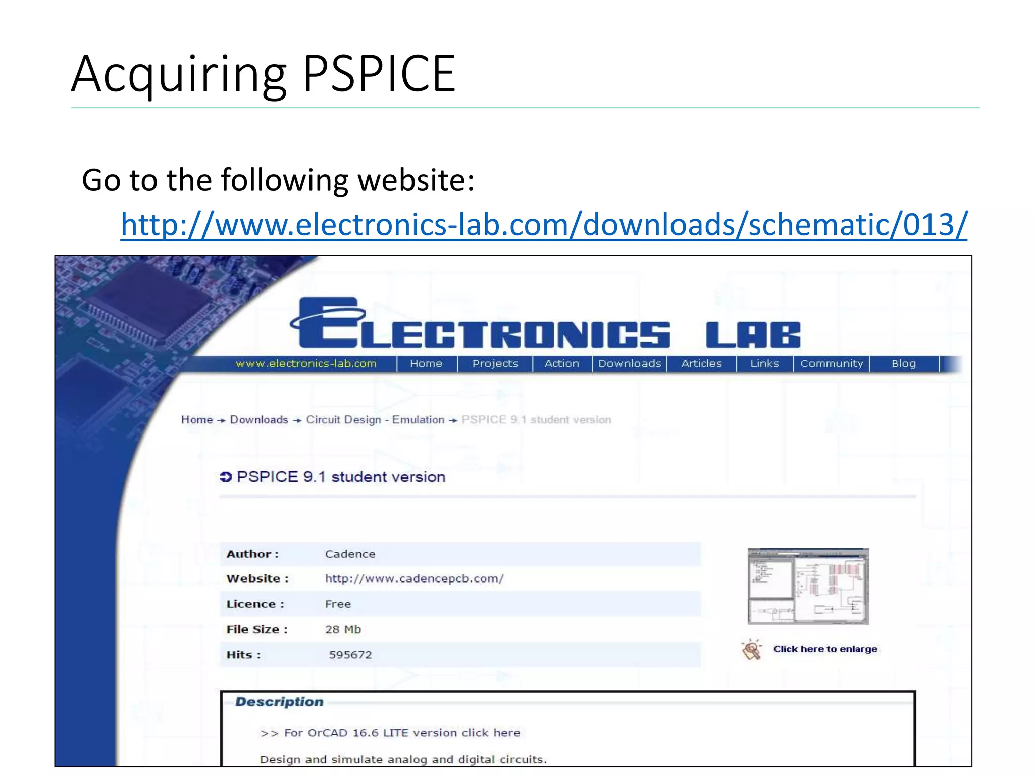
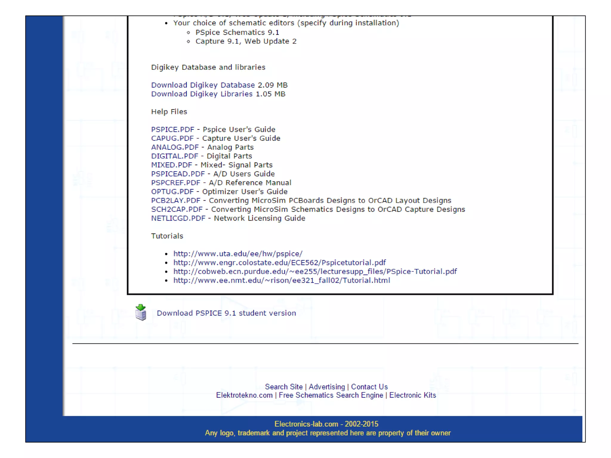
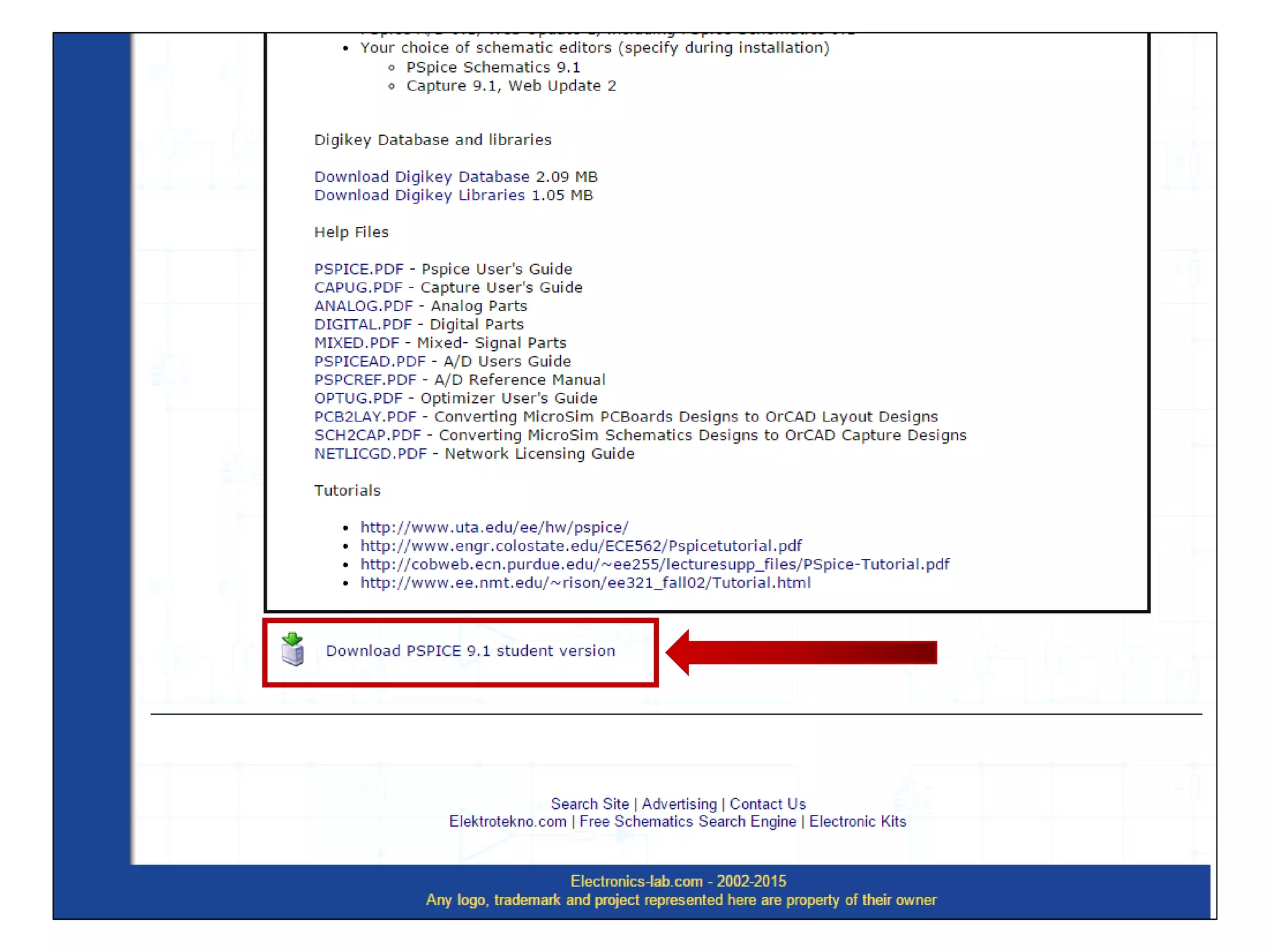
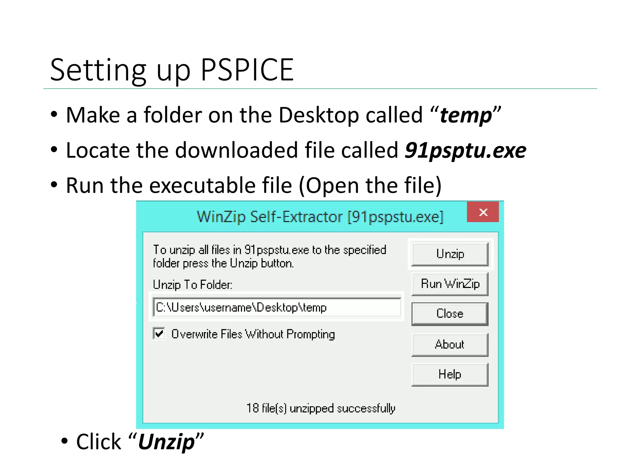
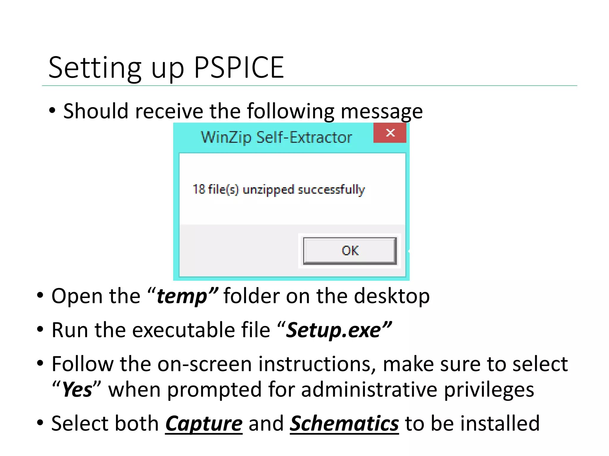
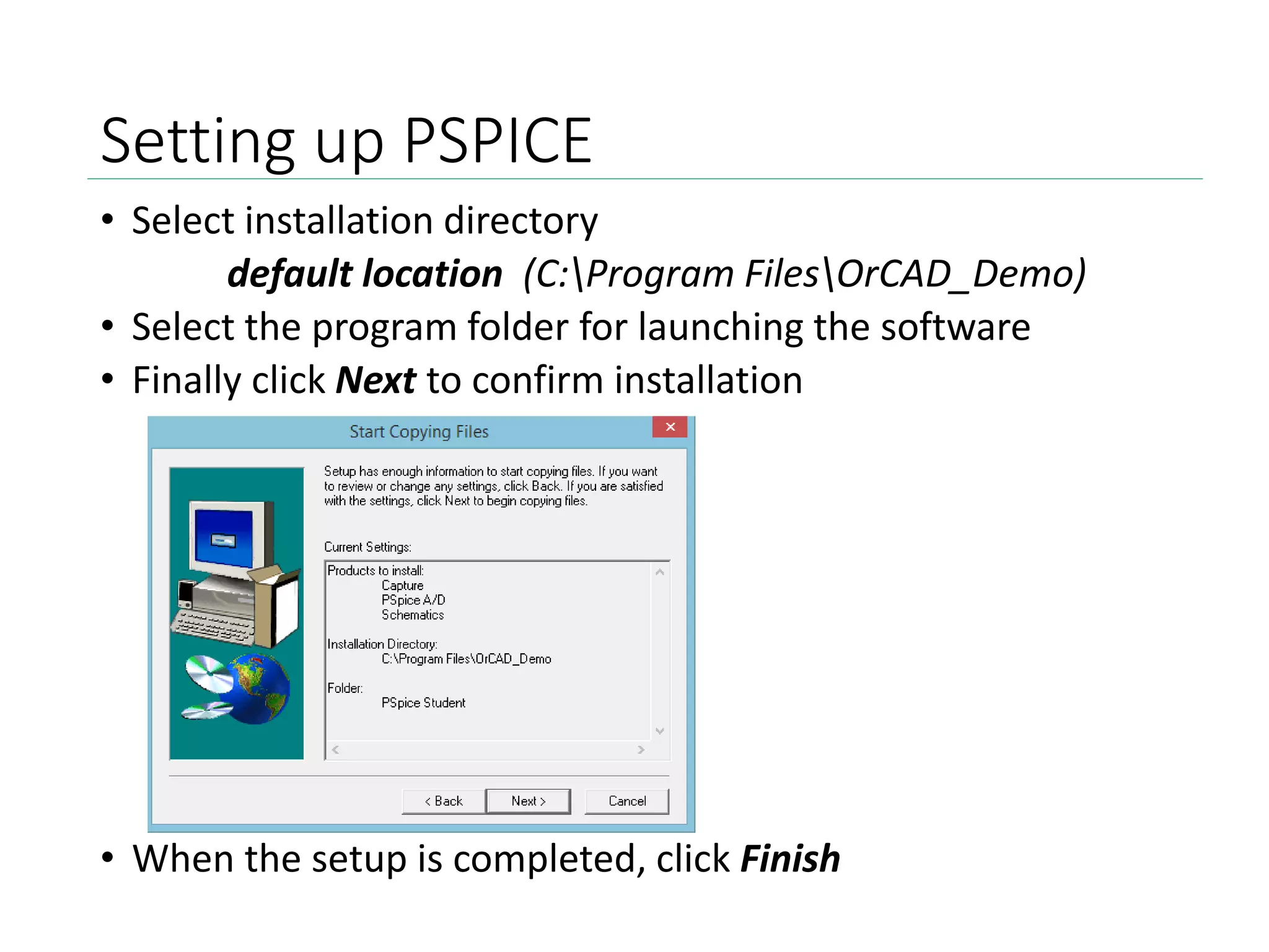
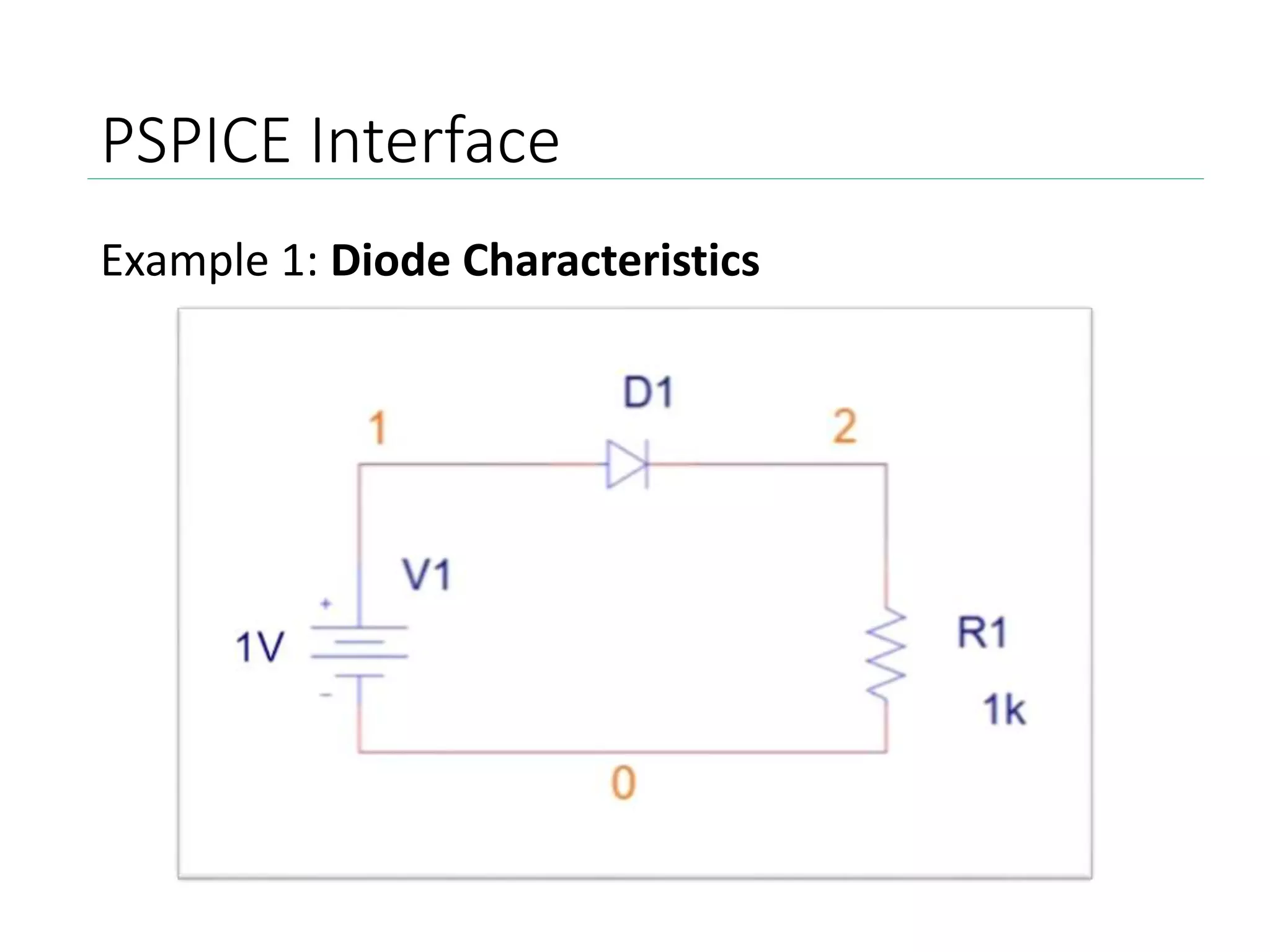
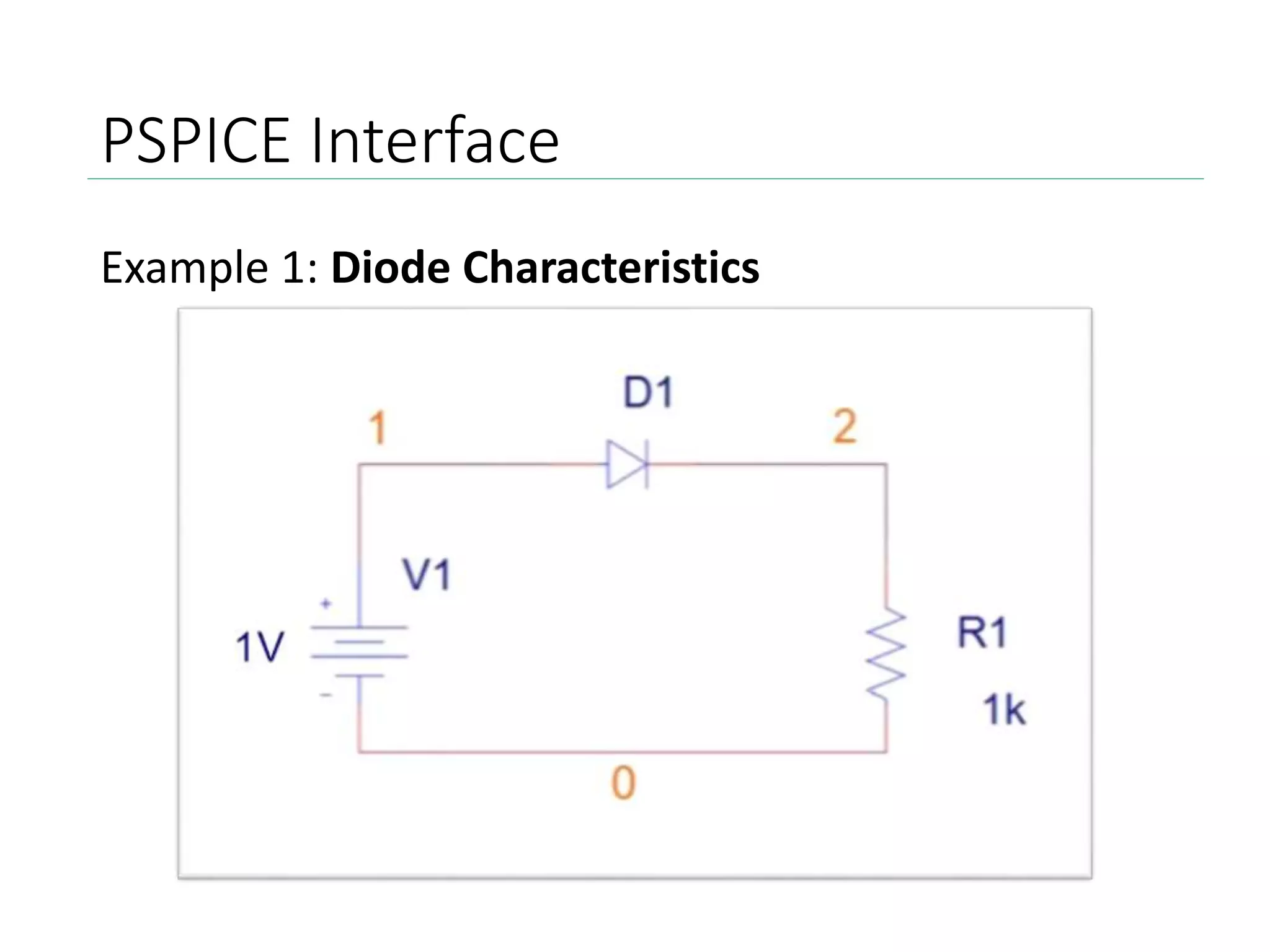
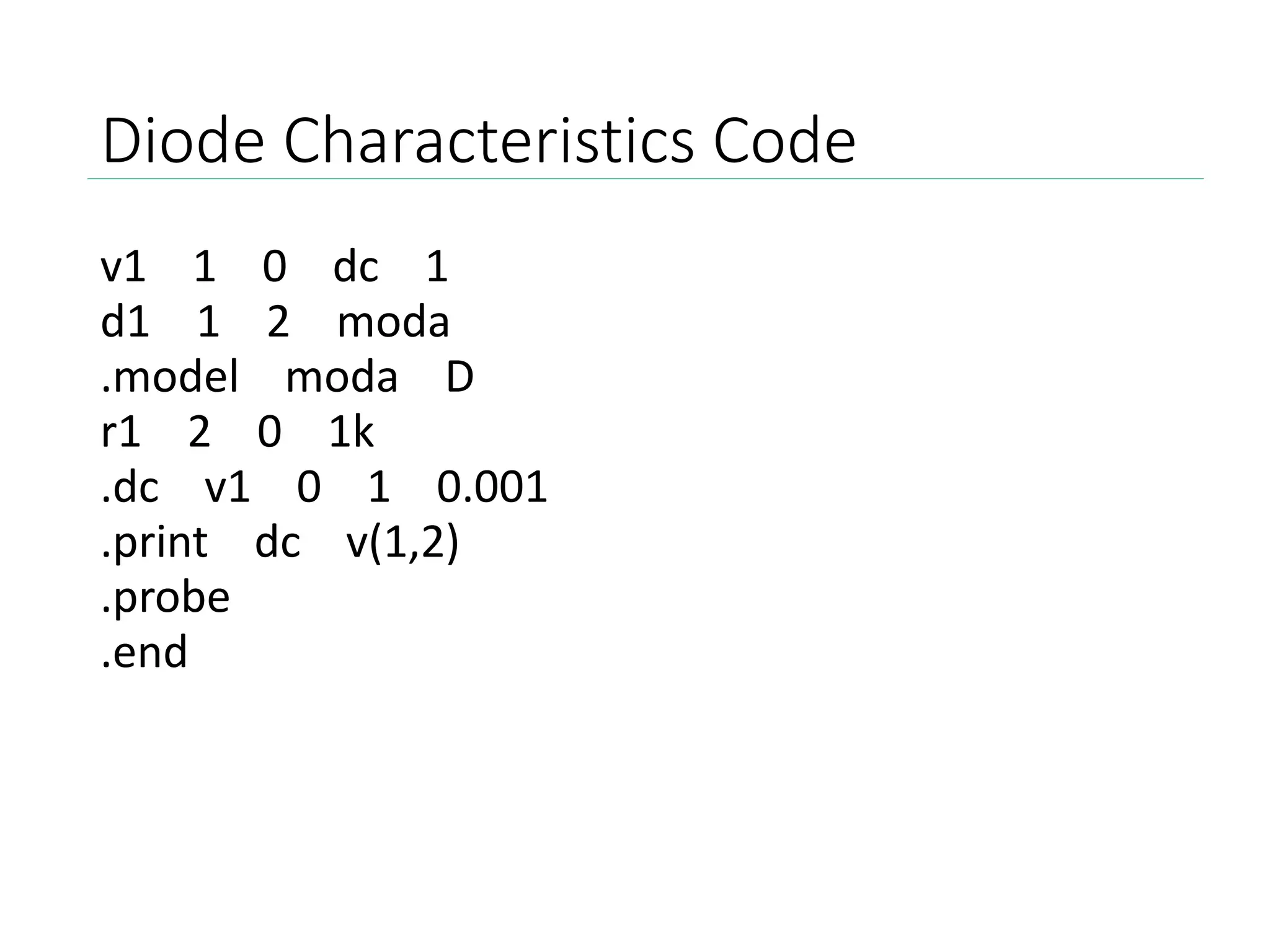
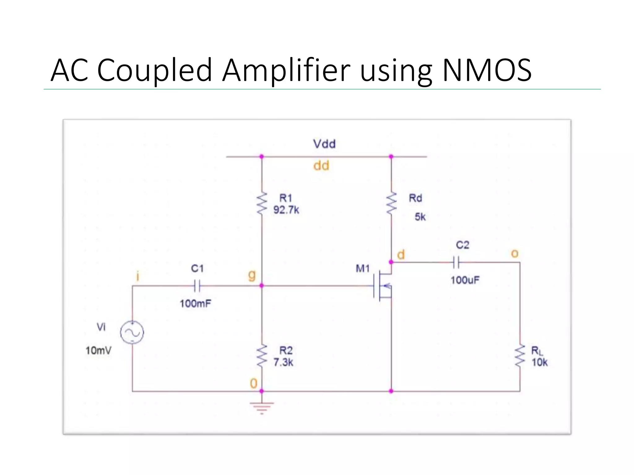
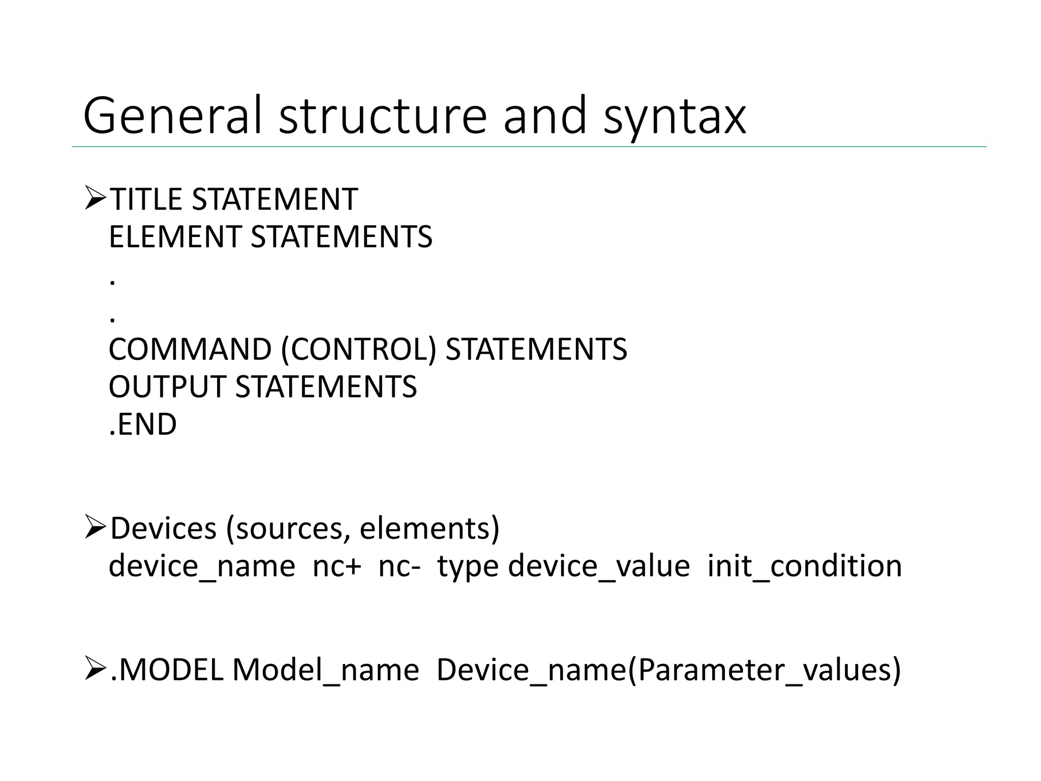
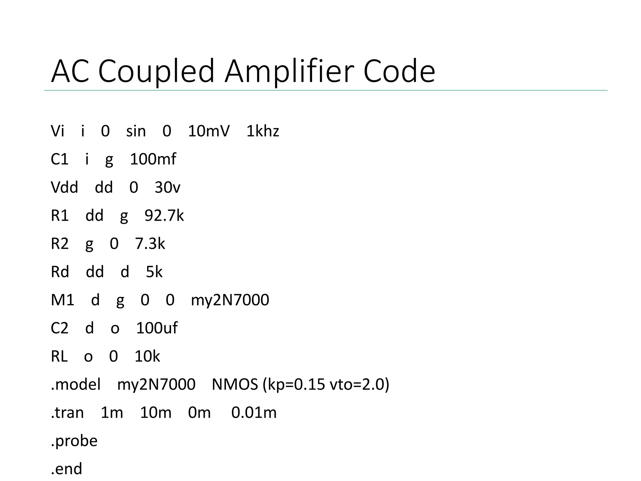
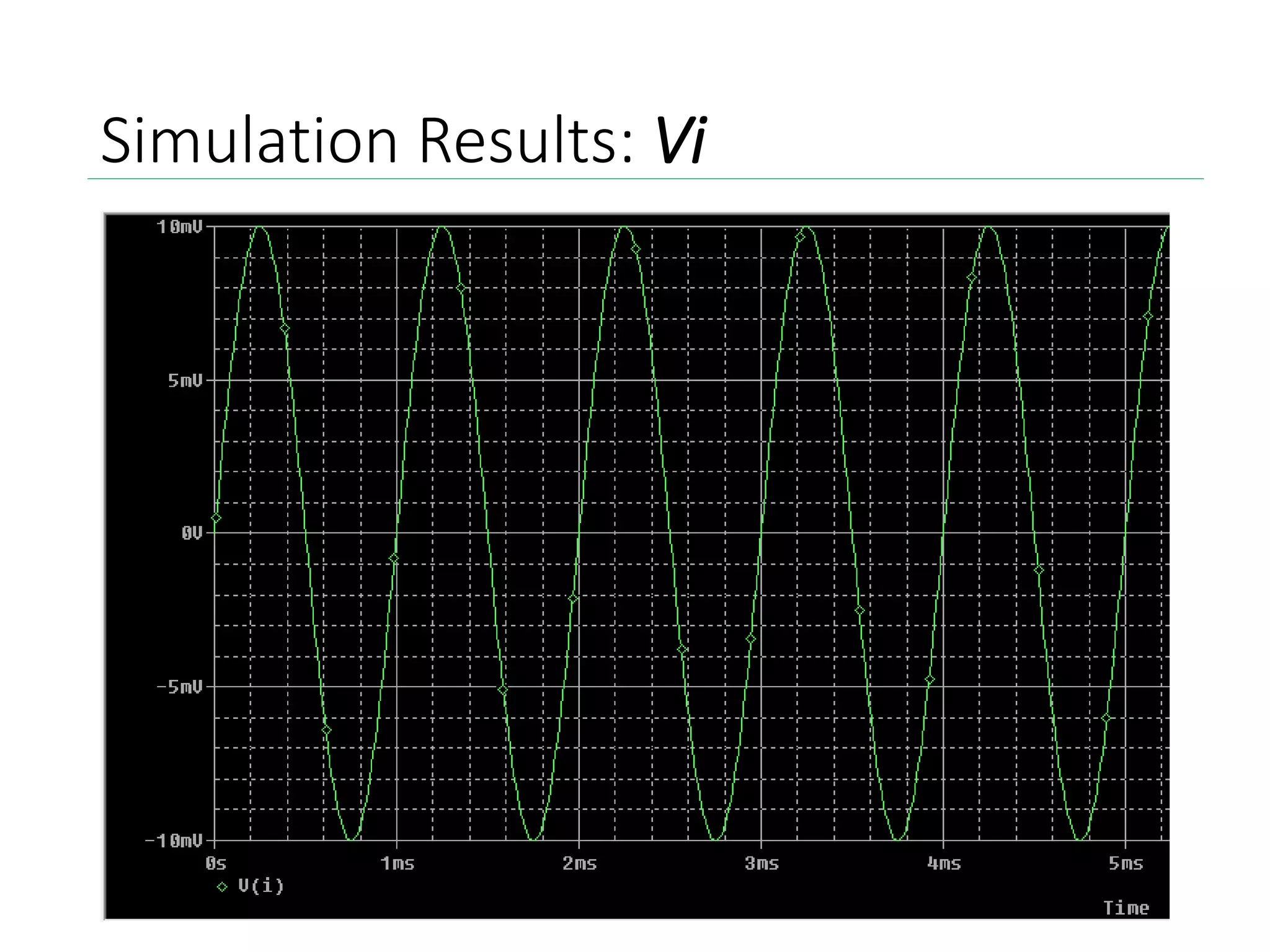
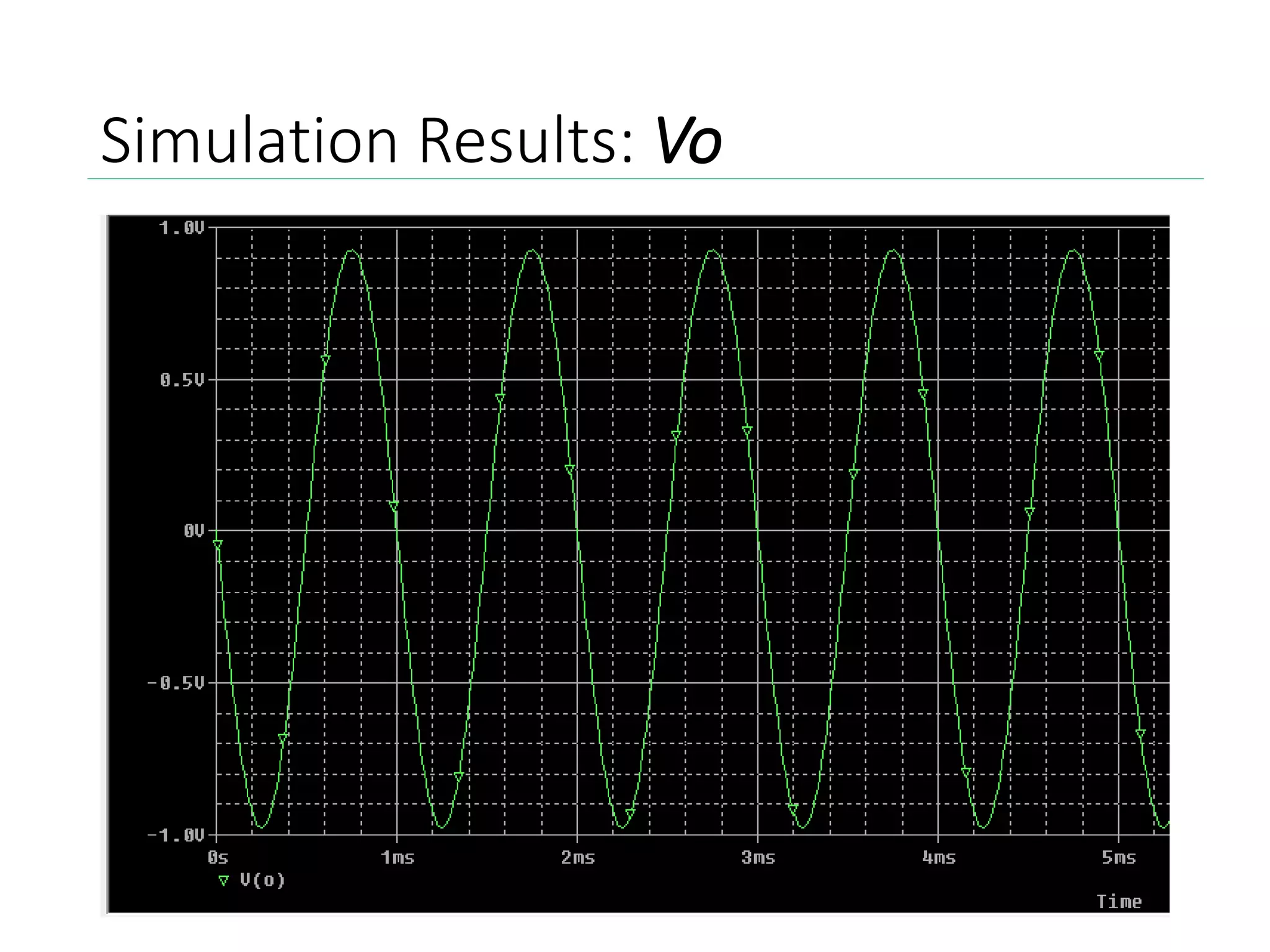
PSPICE
Fundamentals
Introduction to PSPICE
• PSpice is an acronym for Personal Simulation Program
with Integrated Circuits Emphasis
• The software is used to create electronic schematics
and electronic prints for manufacturing PCBs
• The basic input file for PSpice is a text file that has the
file type “.CIR”
• The generated output file is a text file of type “OUT”,
along with the other auxiliary files - .DAT, .PRB
Acquiring PSPICE
Go to the following website:
http://www.electronics-lab.com/downloads/schematic/013/
Setting up PSPICE
• Make a folder on the Desktop called “temp”
• Locate the downloaded file called 91psptu.exe
• Run the executable file (Open the file)
• Click “Unzip”
Setting up PSPICE
• Should receive the following message
• Open the “temp” folder on the desktop
• Run the executable file “Setup.exe”
• Follow the on-screen instructions, make sure to select
“Yes” when prompted for administrative privileges
• Select both Capture and Schematics to be installed
Setting up PSPICE
• Select installation directory
default location (C:Program FilesOrCAD_Demo)
• Select the program folder for launching the software
• Finally click Next to confirm installation
• When the setup is completed, click Finish
Additional Support
Alternate instructions available:
https://www.youtube.com/watch?v=tCFjjHY94Ro
Once again, PSPICE can be downloaded here:
http://www.electronics-
lab.com/downloads/schematic/013/
PSPICE Interface
Example 1: Diode Characteristics
General structure and syntax
TITLE STATEMENT
ELEMENT STATEMENTS
.
.
COMMAND (CONTROL) STATEMENTS
OUTPUT STATEMENTS
.END
Devices (sources, elements)
device_name nc+ nc- type device_value init_condition
.MODEL Model_name Device_name(Parameter_values)
PSPICE Interface
Example 1: Diode Characteristics
Diode Characteristics Code
v1 1 0 dc 1
d1 1 2 moda
.model moda D
r1 2 0 1k
.dc v1 0 1 0.001
.print dc v(1,2)
.probe
.end
Output File
• To access the output file, go to View > Output File
• The output file provides information regarding the circuit
evaluation.
• As well as device model parameters
• Most importantly, it contains the simulation data required
for graphical representation.
• For the diode characteristics, we can observe the DC
transfer curves, as shown in the next slide.
Simulation Results
• To observe the simulation results, go to View >
Simulation Results
High Pass Filter
High Pass Filter Code
Vin 1 0 AC 1.0V
R1 2 0 1.59
C1 1 2 100uF
.AC DEC 20 100Hz 100kHz
.PROBE
.END
Simulation Results
Various PSPICE commands
.model Describes a set of device parameters which are
used in the netlist
.ac Calculates the frequency response over a specified
frequency range
.dc Used to find the DC bias point of the circuit while
specified variable is varying
.tf Calculates the small signal transfer function of the
circuit
.print Creates a table of output signals in the .out file
.probe Used for saving signal data into PROBE.dat,
for viewing simulation results and curve tracings
.end Indicates the end of the circuit description
AC Coupled Amplifier using NMOS
General structure and syntax
TITLE STATEMENT
ELEMENT STATEMENTS
.
.
COMMAND (CONTROL) STATEMENTS
OUTPUT STATEMENTS
.END
Devices (sources, elements)
device_name nc+ nc- type device_value init_condition
.MODEL Model_name Device_name(Parameter_values)
AC Coupled Amplifier Code
Vi i 0 sin 0 10mV 1khz
C1 i g 100mf
Vdd dd 0 30v
R1 dd g 92.7k
R2 g 0 7.3k
Rd dd d 5k
M1 d g 0 0 my2N7000
C2 d o 100uf
RL o 0 10k
.model my2N7000 NMOS (kp=0.15 vto=2.0)
.tran 1m 10m 0m 0.01m
.probe
.end
Simulation Results: Vi
Simulation Results: Vo
Bibliography
• CMOS Digital Integrated Circuits,
by Sung-Mo Kang & Yusuf Leblebici
• www.uta.edu
• www.engr.uky.edu
• http://stuffle.net/references/PSpice_help
• http://ecee.colorado.edu/
• http://home.olemiss.edu/
VLSI Introduction to PSPICE

VLSI Introduction to PSPICE

  • 1.
  • 2.
    Introduction to PSPICE •PSpice is an acronym for Personal Simulation Program with Integrated Circuits Emphasis • The software is used to create electronic schematics and electronic prints for manufacturing PCBs • The basic input file for PSpice is a text file that has the file type “.CIR” • The generated output file is a text file of type “OUT”, along with the other auxiliary files - .DAT, .PRB
  • 3.
    Acquiring PSPICE Go tothe following website: http://www.electronics-lab.com/downloads/schematic/013/
  • 6.
    Setting up PSPICE •Make a folder on the Desktop called “temp” • Locate the downloaded file called 91psptu.exe • Run the executable file (Open the file) • Click “Unzip”
  • 7.
    Setting up PSPICE •Should receive the following message • Open the “temp” folder on the desktop • Run the executable file “Setup.exe” • Follow the on-screen instructions, make sure to select “Yes” when prompted for administrative privileges • Select both Capture and Schematics to be installed
  • 8.
    Setting up PSPICE •Select installation directory default location (C:Program FilesOrCAD_Demo) • Select the program folder for launching the software • Finally click Next to confirm installation • When the setup is completed, click Finish
  • 9.
    Additional Support Alternate instructionsavailable: https://www.youtube.com/watch?v=tCFjjHY94Ro Once again, PSPICE can be downloaded here: http://www.electronics- lab.com/downloads/schematic/013/
  • 10.
    PSPICE Interface Example 1:Diode Characteristics
  • 11.
    General structure andsyntax TITLE STATEMENT ELEMENT STATEMENTS . . COMMAND (CONTROL) STATEMENTS OUTPUT STATEMENTS .END Devices (sources, elements) device_name nc+ nc- type device_value init_condition .MODEL Model_name Device_name(Parameter_values)
  • 12.
    PSPICE Interface Example 1:Diode Characteristics
  • 13.
    Diode Characteristics Code v11 0 dc 1 d1 1 2 moda .model moda D r1 2 0 1k .dc v1 0 1 0.001 .print dc v(1,2) .probe .end
  • 14.
    Output File • Toaccess the output file, go to View > Output File • The output file provides information regarding the circuit evaluation. • As well as device model parameters • Most importantly, it contains the simulation data required for graphical representation. • For the diode characteristics, we can observe the DC transfer curves, as shown in the next slide.
  • 15.
    Simulation Results • Toobserve the simulation results, go to View > Simulation Results
  • 16.
  • 17.
    High Pass FilterCode Vin 1 0 AC 1.0V R1 2 0 1.59 C1 1 2 100uF .AC DEC 20 100Hz 100kHz .PROBE .END
  • 18.
  • 19.
    Various PSPICE commands .modelDescribes a set of device parameters which are used in the netlist .ac Calculates the frequency response over a specified frequency range .dc Used to find the DC bias point of the circuit while specified variable is varying .tf Calculates the small signal transfer function of the circuit .print Creates a table of output signals in the .out file .probe Used for saving signal data into PROBE.dat, for viewing simulation results and curve tracings .end Indicates the end of the circuit description
  • 20.
  • 21.
    General structure andsyntax TITLE STATEMENT ELEMENT STATEMENTS . . COMMAND (CONTROL) STATEMENTS OUTPUT STATEMENTS .END Devices (sources, elements) device_name nc+ nc- type device_value init_condition .MODEL Model_name Device_name(Parameter_values)
  • 22.
    AC Coupled AmplifierCode Vi i 0 sin 0 10mV 1khz C1 i g 100mf Vdd dd 0 30v R1 dd g 92.7k R2 g 0 7.3k Rd dd d 5k M1 d g 0 0 my2N7000 C2 d o 100uf RL o 0 10k .model my2N7000 NMOS (kp=0.15 vto=2.0) .tran 1m 10m 0m 0.01m .probe .end
  • 23.
  • 24.
  • 25.
    Bibliography • CMOS DigitalIntegrated Circuits, by Sung-Mo Kang & Yusuf Leblebici • www.uta.edu • www.engr.uky.edu • http://stuffle.net/references/PSpice_help • http://ecee.colorado.edu/ • http://home.olemiss.edu/