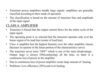
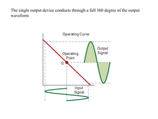
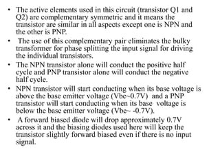
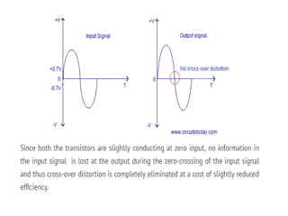
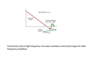
SlideShare a Scribd company logo
POWER AMPLIFIERS
• INTRODUCTION TO POWER AMPLIFIERS
Amplifier system
• Power amplifier is meant to raise the power level of the i/p signal. In order
to get large power at the output, it is necessary that the i/p signal voltage is
large, so an electronic system a voltage amplifier always precedes the
power amplifiers are called large signal amplifiers
• Power amplifier does not amplify power. Power amplifier draws power
from DC supply connected to the output circuit and converts it into useful
AC signal power
• Power amplifier also defined as a device that converts DC power and
whose action controlled by the input signal
TRANSDUCER
SMALL
SIGNAL
AMPLIFIER
LARGE SIGNAL
AMPLIFIER
TRANSDUCER
• Transistor power amplifiers handle large signals .amplifiers are generally
classified according to their mode of operation
• The classification is based on the amount of transistor bias and amplitude
of the input signal
CLASS A AMPLIFIER
• Transistor is biased that the output current flows for the entire cycle of the
input signal
• The operating point is so selected that the transistor operates only over the
linear region of its load line (center of load line).
• Class A amplifier has the highest linearity over the other amplifier classes
(because its operate in the linear portion of the characteristics curve)
• The transistor never turns “OFF” which is one of the main disadvantage .
Output stage is always ON(conducting) all the time, so there is a
continuous loss of power in the amplifier
• Due to continuous loss of power amplifier create large amount of heating
• Problems: Low efficiency (30%) and over heating
The single output device conducts through a full 360 degree of the output
waveform
Series fed class A amplifiers
•It is a fixed bias circuit.
•This circuit is rarely used for power amplification due to its poor
collector efficiency
When an ac signal is applied to the amplifier, the output current and voltage will vary
about the operating point Q . In order to achieve the maximum symmetrical swing of
current and voltage (to achieve maximum output power ), the Q point should be located
at the centre of the dc load line.
Thus, the maximum collector efficiency of a class A series-fed
amplifier is 30% . In actual practice, the collector efficiency is
far less than this value .
Transformer coupled class A amplifier
This is similar to the normal amplifier circuit but connected with a transformer in the
collector load.
•Here R1 and R2 provide potential divider arrangement. The resistor
Re provides stabilization, Ce is the bypass capacitor and Re to prevent
a.c. voltage. The transformer used here is a step-down transformer.
•The high impedance primary of the transformer is connected to the
high impedance collector circuit. The low impedance secondary is
connected to the load (generally loud speaker).
Class A push pull amplifier.
• Q1 and Q2 are two identical transistor and their emitter
terminals are connected together.
• R1 and R2 are meant for biasing the transistors.
• Collector terminals of the two transistor are connected to the
respective ends of the primary of the output transformer T2.
• Power supply is connected between the center tap of the T2
primary and the emitter junction of the Q1 and Q2
• Base terminal of each transistor is connected to the respective
ends of the secondary of the input coupling transformer T1.
• Input signal is applied to the primary of T1 and output load
RL is connected across the secondary of T2.
• From the figure phase splited signals being applied to the
base of each transistors. When Q1 is driven positive using
the first half of its input signal, the collector current of Q1
increases. At the same time Q2 is driven negative using the
first half of its input signal and so the collector current of
Q2 decreases.
• From the figure understand that the collector currents of Q1
and Q2 ie; I1 and I2 flows in the same direction trough the
corresponding halves of the T2 primary. As a result an
amplified version of the original input signal is induced in
the T2 secondary. It is clear that the current through the T2
secondary is the difference between the two collector
currents. Harmonics will be much less in the output due to
cancellation and this is results in low distortion.
Class B amplifier
• The output current flows only during positive half cycle of the
input signal
• At zero signal , the collector current is zero and no biasing
system is required in class B amplifiers
• The operating point is selected at cut-off region
• Compare to class amplifiers average current is less, power
dissipation is less .so efficiency is increased (50%)
• Class B Amplifier only conducts through one half or 180
degree of the output waveform
Class B push pull amplifier.
• The circuit arrangement of the Class B push pull
amplifier is similar to the Class A push pull amplifier
except for the absence of the biasing resistors.
• T1 is the input coupling capacitor and the input signal
is applied to its primary.
• circuit that uses a balanced center-tapped input
transformer, which splits the incoming waveform signal
into two equal halves and which are 180o out of phase
with each other. Another center-tapped transformer on
the output is used to recombined the two signals
providing the increased power to the load.
• The transistors used for this type of transformer push-
pull amplifier circuit are both NPN transistors with
their emitter terminals connected together.
• Since the transistors are not biased they remains OFF when
there is no input signal and no current flows through the load.
Each transistor starts conduction only when the amplitude of
the input signal goes above the base-emitter voltage (Vbe) of
the transistor which is about 0.7 V. This improves the
efficiency but creates a problem called cross-over distortion
• COMPLEMENTARY SYMMETRY CLASS B AMPLIFIER
Check note book
Class AB power amplifier.
• Class AB is a combination of class A and class B
• Class AB amplifiers is currently one of the most common used types
of audio power amplifier design
• In Class AB configuration, the active elements (transistors) are
slightly biased so that the conduction angle is slightly more than
180° but much less than 360°.
• The transistors conduct for more than a half cycle but much less
than the full cycle. That means there will be no instant where both
transistors are OFF simultaneously and thus cross-over distortion is
eliminated.
• Class AB power amplifiers are slightly inefficient than the Class B
configurations but far better in terms of distortion when compared to
Class A configurations.
• Typical efficiency of a well designed class AB power amplifier is
around 70%.
Q point selected above the cut-off region
• The active elements used in this circuit (transistor Q1 and
Q2) are complementary symmetric and it means the
transistor are similar in all aspects except one is NPN and
the other is PNP.
• The use of this complementary pair eliminates the bulky
transformer for phase splitting the input signal for driving
the individual transistors.
• The NPN transistor alone will conduct the positive half
cycle and PNP transistor alone will conduct the negative
half cycle.
• NPN transistor will start conducting when its base voltage is
above the base emitter voltage (Vbe~0.7V) and a PNP
transistor will start conducting when its base voltage is
below the base emitter voltage (Vbe~ -0.7V).
• A forward biased diode will drop approximately 0.7V
across it and the biasing diodes used here will keep the
transistor slightly forward biased even if there is no input
signal.
Class C amplifiers
• Greatest efficiency ,poorest linearity
• Class C amplifiers are heavily biased so that the
output current is zero for more than one half cycle
of an input AC signal
• The conducting angle is less than 180 degree and
is generally around the 90 degree area
• Biasing gives efficiency around 80% to the
amplifier , it introduce a very heavy distortion of
the output signal
• Class C amplifiers are not suitable for use as
audio amplifiers
Commonly used in high frequency sine wave oscillators and certain types of radio
frequency amplifiers
Class C amplifier circuit diagram
• Biasing resistor Rb pulls the base of Q1 downwards and q
point set below the cot-off point in the DC loadline
• As the result the transistor will start conducting only after
input signal amplitude rise above base emitter voltage (.7v)
• The major portion of the input signal is absent in the output
signal.
• Transistor here is to produce a series of current pulses
according to the input and make it flow through the resonant
circuit.
• Inductor L and capacitor C forms a tank circuit which aids
in the extraction of the required signal from the pulsed
output of the transistor. (pulsed output converted to
complete sine wave of a particular frequency by using LC
circuit)
• Class C power amplifiers are never used for power
amplification but as tuned amplifier i.e. to amplify a
narrow band of frequencies near the resonant frequency

More Related Content

What's hot

Silicon control rectifier
Silicon control rectifierSilicon control rectifier
Silicon control rectifier
Mozammel Hoque Parvez
 
Insulated gate bipolar transistor (igbt) - basics
Insulated gate bipolar transistor (igbt) - basicsInsulated gate bipolar transistor (igbt) - basics
Insulated gate bipolar transistor (igbt) - basics
AtheenaPandian Enterprises
 
Power amplifiers
Power amplifiersPower amplifiers
Power amplifiers
Sarah Krystelle
 
(D/A) and (A/D)conversion
(D/A) and (A/D)conversion(D/A) and (A/D)conversion
(D/A) and (A/D)conversion
Praveen Kumar
 
Multivibrators
MultivibratorsMultivibrators
Multivibrators
PrabhudasuSir
 
Op amp
Op ampOp amp
Power amplifier
Power amplifierPower amplifier
Class AB amplifiers
Class AB amplifiersClass AB amplifiers
Class AB amplifiers
kumar Rajshekhar
 
Comparator
ComparatorComparator
Comparator
C035RiteshJadhav
 
Schmitt trigger circuit
Schmitt trigger circuitSchmitt trigger circuit
Schmitt trigger circuit
taranjeet10
 
Amplifier classes
Amplifier classesAmplifier classes
Amplifier classes
mianprogamer
 
Power amplifire analog electronics
Power amplifire analog electronicsPower amplifire analog electronics
Power amplifire analog electronics
rakesh mandiya
 
Power amplifier
Power amplifierPower amplifier
Oscillators
OscillatorsOscillators
Unijunction transistor
Unijunction transistorUnijunction transistor
Unijunction transistor
hepzijustin
 
Power Electronics Chopper (dc – dc converter)
Power Electronics   Chopper (dc – dc converter)Power Electronics   Chopper (dc – dc converter)
Power Electronics Chopper (dc – dc converter)
Burdwan University
 
Multistage amplifier
Multistage amplifierMultistage amplifier
Multistage amplifier
Hansraj Meena
 
Varactor diode
Varactor diodeVaractor diode
Varactor diode
Enock Seth Nyamador
 
Field Effect Transistor (FET)
Field Effect Transistor (FET)Field Effect Transistor (FET)
Field Effect Transistor (FET)
Darwin Nesakumar
 
Tuned amplifire
Tuned amplifireTuned amplifire
Tuned amplifire
rakesh mandiya
 

What's hot (20)

Silicon control rectifier
Silicon control rectifierSilicon control rectifier
Silicon control rectifier
 
Insulated gate bipolar transistor (igbt) - basics
Insulated gate bipolar transistor (igbt) - basicsInsulated gate bipolar transistor (igbt) - basics
Insulated gate bipolar transistor (igbt) - basics
 
Power amplifiers
Power amplifiersPower amplifiers
Power amplifiers
 
(D/A) and (A/D)conversion
(D/A) and (A/D)conversion(D/A) and (A/D)conversion
(D/A) and (A/D)conversion
 
Multivibrators
MultivibratorsMultivibrators
Multivibrators
 
Op amp
Op ampOp amp
Op amp
 
Power amplifier
Power amplifierPower amplifier
Power amplifier
 
Class AB amplifiers
Class AB amplifiersClass AB amplifiers
Class AB amplifiers
 
Comparator
ComparatorComparator
Comparator
 
Schmitt trigger circuit
Schmitt trigger circuitSchmitt trigger circuit
Schmitt trigger circuit
 
Amplifier classes
Amplifier classesAmplifier classes
Amplifier classes
 
Power amplifire analog electronics
Power amplifire analog electronicsPower amplifire analog electronics
Power amplifire analog electronics
 
Power amplifier
Power amplifierPower amplifier
Power amplifier
 
Oscillators
OscillatorsOscillators
Oscillators
 
Unijunction transistor
Unijunction transistorUnijunction transistor
Unijunction transistor
 
Power Electronics Chopper (dc – dc converter)
Power Electronics   Chopper (dc – dc converter)Power Electronics   Chopper (dc – dc converter)
Power Electronics Chopper (dc – dc converter)
 
Multistage amplifier
Multistage amplifierMultistage amplifier
Multistage amplifier
 
Varactor diode
Varactor diodeVaractor diode
Varactor diode
 
Field Effect Transistor (FET)
Field Effect Transistor (FET)Field Effect Transistor (FET)
Field Effect Transistor (FET)
 
Tuned amplifire
Tuned amplifireTuned amplifire
Tuned amplifire
 

Similar to Power amplifiers

Amplifiers.pdf
Amplifiers.pdfAmplifiers.pdf
Amplifiers.pdf
BoseReek
 
Eedp lect 06 amplifiers_3_classes
Eedp lect 06 amplifiers_3_classesEedp lect 06 amplifiers_3_classes
Eedp lect 06 amplifiers_3_classes
focusud
 
power amplifier -IT IS ONE OF THE AMPLIFIER WHICH CAN HANDLE LARGER SIGNALS
power amplifier -IT IS ONE OF THE AMPLIFIER WHICH CAN HANDLE LARGER SIGNALSpower amplifier -IT IS ONE OF THE AMPLIFIER WHICH CAN HANDLE LARGER SIGNALS
power amplifier -IT IS ONE OF THE AMPLIFIER WHICH CAN HANDLE LARGER SIGNALS
Abinaya Saraswathy T
 
Lingad3
Lingad3Lingad3
Ece 312 power point
Ece 312 power pointEce 312 power point
Ece 312 power point
Emmanuel Alipar
 
P2 amplifier
P2 amplifierP2 amplifier
P2 amplifier
Mohammed Rizwan
 
Class a amplifier
Class a amplifierClass a amplifier
Class a amplifier
imSagi
 
POWER AMPLIFIER- introduction to power amplifier.pptx
POWER AMPLIFIER- introduction to power amplifier.pptxPOWER AMPLIFIER- introduction to power amplifier.pptx
POWER AMPLIFIER- introduction to power amplifier.pptx
DrVikasMahor
 
Amplifier
AmplifierAmplifier
Amplifier
Sandeep Sharma
 
unit 1 ppt 2 Multi-stage transistor amplifiers (1).pptx
unit 1 ppt 2 Multi-stage transistor amplifiers (1).pptxunit 1 ppt 2 Multi-stage transistor amplifiers (1).pptx
unit 1 ppt 2 Multi-stage transistor amplifiers (1).pptx
hipiko5945
 
Transistor applications
Transistor applicationsTransistor applications
Transistor applications
HarshitParkar6677
 
Transistor applications (2)
Transistor applications (2)Transistor applications (2)
Transistor applications (2)
HarshitParkar6677
 
Class a amplifier5
Class a amplifier5Class a amplifier5
Class a amplifier5
Sarah Krystelle
 
A Class-C Power Amplifiers Type of Tuned Amplifiers
A Class-C Power Amplifiers Type of Tuned AmplifiersA Class-C Power Amplifiers Type of Tuned Amplifiers
A Class-C Power Amplifiers Type of Tuned Amplifiers
ShahbazQamar2
 
Switching regulators
Switching regulatorsSwitching regulators
Switching regulators
vishalgohel12195
 
Amplifier (Transformer Coupled)
Amplifier (Transformer Coupled)Amplifier (Transformer Coupled)
Amplifier (Transformer Coupled)
Arpan Bose
 
Tagasa1
Tagasa1Tagasa1
Voltage Amplifier
Voltage AmplifierVoltage Amplifier
Voltage Amplifier
Mayank Pandey
 
Rectifier and Filter circuits (chapter14)
Rectifier and Filter circuits (chapter14)Rectifier and Filter circuits (chapter14)
Rectifier and Filter circuits (chapter14)
DHARUN MUGHILAN
 
Oscillator
OscillatorOscillator
Oscillator
Ankit Dubey
 

Similar to Power amplifiers (20)

Amplifiers.pdf
Amplifiers.pdfAmplifiers.pdf
Amplifiers.pdf
 
Eedp lect 06 amplifiers_3_classes
Eedp lect 06 amplifiers_3_classesEedp lect 06 amplifiers_3_classes
Eedp lect 06 amplifiers_3_classes
 
power amplifier -IT IS ONE OF THE AMPLIFIER WHICH CAN HANDLE LARGER SIGNALS
power amplifier -IT IS ONE OF THE AMPLIFIER WHICH CAN HANDLE LARGER SIGNALSpower amplifier -IT IS ONE OF THE AMPLIFIER WHICH CAN HANDLE LARGER SIGNALS
power amplifier -IT IS ONE OF THE AMPLIFIER WHICH CAN HANDLE LARGER SIGNALS
 
Lingad3
Lingad3Lingad3
Lingad3
 
Ece 312 power point
Ece 312 power pointEce 312 power point
Ece 312 power point
 
P2 amplifier
P2 amplifierP2 amplifier
P2 amplifier
 
Class a amplifier
Class a amplifierClass a amplifier
Class a amplifier
 
POWER AMPLIFIER- introduction to power amplifier.pptx
POWER AMPLIFIER- introduction to power amplifier.pptxPOWER AMPLIFIER- introduction to power amplifier.pptx
POWER AMPLIFIER- introduction to power amplifier.pptx
 
Amplifier
AmplifierAmplifier
Amplifier
 
unit 1 ppt 2 Multi-stage transistor amplifiers (1).pptx
unit 1 ppt 2 Multi-stage transistor amplifiers (1).pptxunit 1 ppt 2 Multi-stage transistor amplifiers (1).pptx
unit 1 ppt 2 Multi-stage transistor amplifiers (1).pptx
 
Transistor applications
Transistor applicationsTransistor applications
Transistor applications
 
Transistor applications (2)
Transistor applications (2)Transistor applications (2)
Transistor applications (2)
 
Class a amplifier5
Class a amplifier5Class a amplifier5
Class a amplifier5
 
A Class-C Power Amplifiers Type of Tuned Amplifiers
A Class-C Power Amplifiers Type of Tuned AmplifiersA Class-C Power Amplifiers Type of Tuned Amplifiers
A Class-C Power Amplifiers Type of Tuned Amplifiers
 
Switching regulators
Switching regulatorsSwitching regulators
Switching regulators
 
Amplifier (Transformer Coupled)
Amplifier (Transformer Coupled)Amplifier (Transformer Coupled)
Amplifier (Transformer Coupled)
 
Tagasa1
Tagasa1Tagasa1
Tagasa1
 
Voltage Amplifier
Voltage AmplifierVoltage Amplifier
Voltage Amplifier
 
Rectifier and Filter circuits (chapter14)
Rectifier and Filter circuits (chapter14)Rectifier and Filter circuits (chapter14)
Rectifier and Filter circuits (chapter14)
 
Oscillator
OscillatorOscillator
Oscillator
 

Recently uploaded

Recycled Concrete Aggregate in Construction Part III
Recycled Concrete Aggregate in Construction Part IIIRecycled Concrete Aggregate in Construction Part III
Recycled Concrete Aggregate in Construction Part III
Aditya Rajan Patra
 
Iron and Steel Technology Roadmap - Towards more sustainable steelmaking.pdf
Iron and Steel Technology Roadmap - Towards more sustainable steelmaking.pdfIron and Steel Technology Roadmap - Towards more sustainable steelmaking.pdf
Iron and Steel Technology Roadmap - Towards more sustainable steelmaking.pdf
RadiNasr
 
Heat Resistant Concrete Presentation ppt
Heat Resistant Concrete Presentation pptHeat Resistant Concrete Presentation ppt
Heat Resistant Concrete Presentation ppt
mamunhossenbd75
 
A SYSTEMATIC RISK ASSESSMENT APPROACH FOR SECURING THE SMART IRRIGATION SYSTEMS
A SYSTEMATIC RISK ASSESSMENT APPROACH FOR SECURING THE SMART IRRIGATION SYSTEMSA SYSTEMATIC RISK ASSESSMENT APPROACH FOR SECURING THE SMART IRRIGATION SYSTEMS
A SYSTEMATIC RISK ASSESSMENT APPROACH FOR SECURING THE SMART IRRIGATION SYSTEMS
IJNSA Journal
 
Question paper of renewable energy sources
Question paper of renewable energy sourcesQuestion paper of renewable energy sources
Question paper of renewable energy sources
mahammadsalmanmech
 
Manufacturing Process of molasses based distillery ppt.pptx
Manufacturing Process of molasses based distillery ppt.pptxManufacturing Process of molasses based distillery ppt.pptx
Manufacturing Process of molasses based distillery ppt.pptx
Madan Karki
 
Understanding Inductive Bias in Machine Learning
Understanding Inductive Bias in Machine LearningUnderstanding Inductive Bias in Machine Learning
Understanding Inductive Bias in Machine Learning
SUTEJAS
 
ML Based Model for NIDS MSc Updated Presentation.v2.pptx
ML Based Model for NIDS MSc Updated Presentation.v2.pptxML Based Model for NIDS MSc Updated Presentation.v2.pptx
ML Based Model for NIDS MSc Updated Presentation.v2.pptx
JamalHussainArman
 
Electric vehicle and photovoltaic advanced roles in enhancing the financial p...
Electric vehicle and photovoltaic advanced roles in enhancing the financial p...Electric vehicle and photovoltaic advanced roles in enhancing the financial p...
Electric vehicle and photovoltaic advanced roles in enhancing the financial p...
IJECEIAES
 
New techniques for characterising damage in rock slopes.pdf
New techniques for characterising damage in rock slopes.pdfNew techniques for characterising damage in rock slopes.pdf
New techniques for characterising damage in rock slopes.pdf
wisnuprabawa3
 
RAT: Retrieval Augmented Thoughts Elicit Context-Aware Reasoning in Long-Hori...
RAT: Retrieval Augmented Thoughts Elicit Context-Aware Reasoning in Long-Hori...RAT: Retrieval Augmented Thoughts Elicit Context-Aware Reasoning in Long-Hori...
RAT: Retrieval Augmented Thoughts Elicit Context-Aware Reasoning in Long-Hori...
thanhdowork
 
Literature Review Basics and Understanding Reference Management.pptx
Literature Review Basics and Understanding Reference Management.pptxLiterature Review Basics and Understanding Reference Management.pptx
Literature Review Basics and Understanding Reference Management.pptx
Dr Ramhari Poudyal
 
Low power architecture of logic gates using adiabatic techniques
Low power architecture of logic gates using adiabatic techniquesLow power architecture of logic gates using adiabatic techniques
Low power architecture of logic gates using adiabatic techniques
nooriasukmaningtyas
 
Exception Handling notes in java exception
Exception Handling notes in java exceptionException Handling notes in java exception
Exception Handling notes in java exception
Ratnakar Mikkili
 
Harnessing WebAssembly for Real-time Stateless Streaming Pipelines
Harnessing WebAssembly for Real-time Stateless Streaming PipelinesHarnessing WebAssembly for Real-time Stateless Streaming Pipelines
Harnessing WebAssembly for Real-time Stateless Streaming Pipelines
Christina Lin
 
5214-1693458878915-Unit 6 2023 to 2024 academic year assignment (AutoRecovere...
5214-1693458878915-Unit 6 2023 to 2024 academic year assignment (AutoRecovere...5214-1693458878915-Unit 6 2023 to 2024 academic year assignment (AutoRecovere...
5214-1693458878915-Unit 6 2023 to 2024 academic year assignment (AutoRecovere...
ihlasbinance2003
 
PPT on GRP pipes manufacturing and testing
PPT on GRP pipes manufacturing and testingPPT on GRP pipes manufacturing and testing
PPT on GRP pipes manufacturing and testing
anoopmanoharan2
 
Wearable antenna for antenna applications
Wearable antenna for antenna applicationsWearable antenna for antenna applications
Wearable antenna for antenna applications
Madhumitha Jayaram
 
ACEP Magazine edition 4th launched on 05.06.2024
ACEP Magazine edition 4th launched on 05.06.2024ACEP Magazine edition 4th launched on 05.06.2024
ACEP Magazine edition 4th launched on 05.06.2024
Rahul
 
ACRP 4-09 Risk Assessment Method to Support Modification of Airfield Separat...
ACRP 4-09 Risk Assessment Method to Support Modification of Airfield Separat...ACRP 4-09 Risk Assessment Method to Support Modification of Airfield Separat...
ACRP 4-09 Risk Assessment Method to Support Modification of Airfield Separat...
Mukeshwaran Balu
 

Recently uploaded (20)

Recycled Concrete Aggregate in Construction Part III
Recycled Concrete Aggregate in Construction Part IIIRecycled Concrete Aggregate in Construction Part III
Recycled Concrete Aggregate in Construction Part III
 
Iron and Steel Technology Roadmap - Towards more sustainable steelmaking.pdf
Iron and Steel Technology Roadmap - Towards more sustainable steelmaking.pdfIron and Steel Technology Roadmap - Towards more sustainable steelmaking.pdf
Iron and Steel Technology Roadmap - Towards more sustainable steelmaking.pdf
 
Heat Resistant Concrete Presentation ppt
Heat Resistant Concrete Presentation pptHeat Resistant Concrete Presentation ppt
Heat Resistant Concrete Presentation ppt
 
A SYSTEMATIC RISK ASSESSMENT APPROACH FOR SECURING THE SMART IRRIGATION SYSTEMS
A SYSTEMATIC RISK ASSESSMENT APPROACH FOR SECURING THE SMART IRRIGATION SYSTEMSA SYSTEMATIC RISK ASSESSMENT APPROACH FOR SECURING THE SMART IRRIGATION SYSTEMS
A SYSTEMATIC RISK ASSESSMENT APPROACH FOR SECURING THE SMART IRRIGATION SYSTEMS
 
Question paper of renewable energy sources
Question paper of renewable energy sourcesQuestion paper of renewable energy sources
Question paper of renewable energy sources
 
Manufacturing Process of molasses based distillery ppt.pptx
Manufacturing Process of molasses based distillery ppt.pptxManufacturing Process of molasses based distillery ppt.pptx
Manufacturing Process of molasses based distillery ppt.pptx
 
Understanding Inductive Bias in Machine Learning
Understanding Inductive Bias in Machine LearningUnderstanding Inductive Bias in Machine Learning
Understanding Inductive Bias in Machine Learning
 
ML Based Model for NIDS MSc Updated Presentation.v2.pptx
ML Based Model for NIDS MSc Updated Presentation.v2.pptxML Based Model for NIDS MSc Updated Presentation.v2.pptx
ML Based Model for NIDS MSc Updated Presentation.v2.pptx
 
Electric vehicle and photovoltaic advanced roles in enhancing the financial p...
Electric vehicle and photovoltaic advanced roles in enhancing the financial p...Electric vehicle and photovoltaic advanced roles in enhancing the financial p...
Electric vehicle and photovoltaic advanced roles in enhancing the financial p...
 
New techniques for characterising damage in rock slopes.pdf
New techniques for characterising damage in rock slopes.pdfNew techniques for characterising damage in rock slopes.pdf
New techniques for characterising damage in rock slopes.pdf
 
RAT: Retrieval Augmented Thoughts Elicit Context-Aware Reasoning in Long-Hori...
RAT: Retrieval Augmented Thoughts Elicit Context-Aware Reasoning in Long-Hori...RAT: Retrieval Augmented Thoughts Elicit Context-Aware Reasoning in Long-Hori...
RAT: Retrieval Augmented Thoughts Elicit Context-Aware Reasoning in Long-Hori...
 
Literature Review Basics and Understanding Reference Management.pptx
Literature Review Basics and Understanding Reference Management.pptxLiterature Review Basics and Understanding Reference Management.pptx
Literature Review Basics and Understanding Reference Management.pptx
 
Low power architecture of logic gates using adiabatic techniques
Low power architecture of logic gates using adiabatic techniquesLow power architecture of logic gates using adiabatic techniques
Low power architecture of logic gates using adiabatic techniques
 
Exception Handling notes in java exception
Exception Handling notes in java exceptionException Handling notes in java exception
Exception Handling notes in java exception
 
Harnessing WebAssembly for Real-time Stateless Streaming Pipelines
Harnessing WebAssembly for Real-time Stateless Streaming PipelinesHarnessing WebAssembly for Real-time Stateless Streaming Pipelines
Harnessing WebAssembly for Real-time Stateless Streaming Pipelines
 
5214-1693458878915-Unit 6 2023 to 2024 academic year assignment (AutoRecovere...
5214-1693458878915-Unit 6 2023 to 2024 academic year assignment (AutoRecovere...5214-1693458878915-Unit 6 2023 to 2024 academic year assignment (AutoRecovere...
5214-1693458878915-Unit 6 2023 to 2024 academic year assignment (AutoRecovere...
 
PPT on GRP pipes manufacturing and testing
PPT on GRP pipes manufacturing and testingPPT on GRP pipes manufacturing and testing
PPT on GRP pipes manufacturing and testing
 
Wearable antenna for antenna applications
Wearable antenna for antenna applicationsWearable antenna for antenna applications
Wearable antenna for antenna applications
 
ACEP Magazine edition 4th launched on 05.06.2024
ACEP Magazine edition 4th launched on 05.06.2024ACEP Magazine edition 4th launched on 05.06.2024
ACEP Magazine edition 4th launched on 05.06.2024
 
ACRP 4-09 Risk Assessment Method to Support Modification of Airfield Separat...
ACRP 4-09 Risk Assessment Method to Support Modification of Airfield Separat...ACRP 4-09 Risk Assessment Method to Support Modification of Airfield Separat...
ACRP 4-09 Risk Assessment Method to Support Modification of Airfield Separat...
 

Power amplifiers

  • 2. • INTRODUCTION TO POWER AMPLIFIERS Amplifier system • Power amplifier is meant to raise the power level of the i/p signal. In order to get large power at the output, it is necessary that the i/p signal voltage is large, so an electronic system a voltage amplifier always precedes the power amplifiers are called large signal amplifiers • Power amplifier does not amplify power. Power amplifier draws power from DC supply connected to the output circuit and converts it into useful AC signal power • Power amplifier also defined as a device that converts DC power and whose action controlled by the input signal TRANSDUCER SMALL SIGNAL AMPLIFIER LARGE SIGNAL AMPLIFIER TRANSDUCER
  • 3. • Transistor power amplifiers handle large signals .amplifiers are generally classified according to their mode of operation • The classification is based on the amount of transistor bias and amplitude of the input signal CLASS A AMPLIFIER • Transistor is biased that the output current flows for the entire cycle of the input signal • The operating point is so selected that the transistor operates only over the linear region of its load line (center of load line). • Class A amplifier has the highest linearity over the other amplifier classes (because its operate in the linear portion of the characteristics curve) • The transistor never turns “OFF” which is one of the main disadvantage . Output stage is always ON(conducting) all the time, so there is a continuous loss of power in the amplifier • Due to continuous loss of power amplifier create large amount of heating • Problems: Low efficiency (30%) and over heating
  • 4. The single output device conducts through a full 360 degree of the output waveform
  • 5. Series fed class A amplifiers •It is a fixed bias circuit. •This circuit is rarely used for power amplification due to its poor collector efficiency
  • 6. When an ac signal is applied to the amplifier, the output current and voltage will vary about the operating point Q . In order to achieve the maximum symmetrical swing of current and voltage (to achieve maximum output power ), the Q point should be located at the centre of the dc load line.
  • 7. Thus, the maximum collector efficiency of a class A series-fed amplifier is 30% . In actual practice, the collector efficiency is far less than this value .
  • 8. Transformer coupled class A amplifier This is similar to the normal amplifier circuit but connected with a transformer in the collector load.
  • 9. •Here R1 and R2 provide potential divider arrangement. The resistor Re provides stabilization, Ce is the bypass capacitor and Re to prevent a.c. voltage. The transformer used here is a step-down transformer. •The high impedance primary of the transformer is connected to the high impedance collector circuit. The low impedance secondary is connected to the load (generally loud speaker).
  • 10.
  • 11.
  • 12.
  • 13.
  • 14. Class A push pull amplifier.
  • 15. • Q1 and Q2 are two identical transistor and their emitter terminals are connected together. • R1 and R2 are meant for biasing the transistors. • Collector terminals of the two transistor are connected to the respective ends of the primary of the output transformer T2. • Power supply is connected between the center tap of the T2 primary and the emitter junction of the Q1 and Q2 • Base terminal of each transistor is connected to the respective ends of the secondary of the input coupling transformer T1. • Input signal is applied to the primary of T1 and output load RL is connected across the secondary of T2.
  • 16. • From the figure phase splited signals being applied to the base of each transistors. When Q1 is driven positive using the first half of its input signal, the collector current of Q1 increases. At the same time Q2 is driven negative using the first half of its input signal and so the collector current of Q2 decreases. • From the figure understand that the collector currents of Q1 and Q2 ie; I1 and I2 flows in the same direction trough the corresponding halves of the T2 primary. As a result an amplified version of the original input signal is induced in the T2 secondary. It is clear that the current through the T2 secondary is the difference between the two collector currents. Harmonics will be much less in the output due to cancellation and this is results in low distortion.
  • 17. Class B amplifier • The output current flows only during positive half cycle of the input signal • At zero signal , the collector current is zero and no biasing system is required in class B amplifiers • The operating point is selected at cut-off region • Compare to class amplifiers average current is less, power dissipation is less .so efficiency is increased (50%) • Class B Amplifier only conducts through one half or 180 degree of the output waveform
  • 18.
  • 19. Class B push pull amplifier.
  • 20. • The circuit arrangement of the Class B push pull amplifier is similar to the Class A push pull amplifier except for the absence of the biasing resistors. • T1 is the input coupling capacitor and the input signal is applied to its primary. • circuit that uses a balanced center-tapped input transformer, which splits the incoming waveform signal into two equal halves and which are 180o out of phase with each other. Another center-tapped transformer on the output is used to recombined the two signals providing the increased power to the load. • The transistors used for this type of transformer push- pull amplifier circuit are both NPN transistors with their emitter terminals connected together.
  • 21. • Since the transistors are not biased they remains OFF when there is no input signal and no current flows through the load. Each transistor starts conduction only when the amplitude of the input signal goes above the base-emitter voltage (Vbe) of the transistor which is about 0.7 V. This improves the efficiency but creates a problem called cross-over distortion • COMPLEMENTARY SYMMETRY CLASS B AMPLIFIER Check note book
  • 22.
  • 23. Class AB power amplifier. • Class AB is a combination of class A and class B • Class AB amplifiers is currently one of the most common used types of audio power amplifier design • In Class AB configuration, the active elements (transistors) are slightly biased so that the conduction angle is slightly more than 180° but much less than 360°. • The transistors conduct for more than a half cycle but much less than the full cycle. That means there will be no instant where both transistors are OFF simultaneously and thus cross-over distortion is eliminated. • Class AB power amplifiers are slightly inefficient than the Class B configurations but far better in terms of distortion when compared to Class A configurations. • Typical efficiency of a well designed class AB power amplifier is around 70%.
  • 24. Q point selected above the cut-off region
  • 25.
  • 26. • The active elements used in this circuit (transistor Q1 and Q2) are complementary symmetric and it means the transistor are similar in all aspects except one is NPN and the other is PNP. • The use of this complementary pair eliminates the bulky transformer for phase splitting the input signal for driving the individual transistors. • The NPN transistor alone will conduct the positive half cycle and PNP transistor alone will conduct the negative half cycle. • NPN transistor will start conducting when its base voltage is above the base emitter voltage (Vbe~0.7V) and a PNP transistor will start conducting when its base voltage is below the base emitter voltage (Vbe~ -0.7V). • A forward biased diode will drop approximately 0.7V across it and the biasing diodes used here will keep the transistor slightly forward biased even if there is no input signal.
  • 27.
  • 28. Class C amplifiers • Greatest efficiency ,poorest linearity • Class C amplifiers are heavily biased so that the output current is zero for more than one half cycle of an input AC signal • The conducting angle is less than 180 degree and is generally around the 90 degree area • Biasing gives efficiency around 80% to the amplifier , it introduce a very heavy distortion of the output signal • Class C amplifiers are not suitable for use as audio amplifiers
  • 29. Commonly used in high frequency sine wave oscillators and certain types of radio frequency amplifiers
  • 30. Class C amplifier circuit diagram
  • 31. • Biasing resistor Rb pulls the base of Q1 downwards and q point set below the cot-off point in the DC loadline • As the result the transistor will start conducting only after input signal amplitude rise above base emitter voltage (.7v) • The major portion of the input signal is absent in the output signal. • Transistor here is to produce a series of current pulses according to the input and make it flow through the resonant circuit. • Inductor L and capacitor C forms a tank circuit which aids in the extraction of the required signal from the pulsed output of the transistor. (pulsed output converted to complete sine wave of a particular frequency by using LC circuit) • Class C power amplifiers are never used for power amplification but as tuned amplifier i.e. to amplify a narrow band of frequencies near the resonant frequency